
Related Manuals for AXIOMTEK PICO841


Summary of Contents for AXIOMTEK PICO841
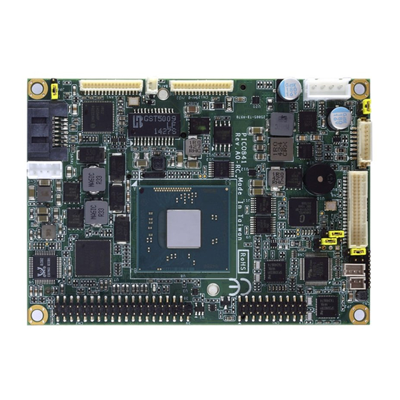
- Page 1 PICO841/843 ® Intel Atom E3845/E3827 ® ® Intel Celeron J1900/N2807 Processors Pico-ITX Board User’s Manual...
-
Page 2: Disclaimers
Axiomtek does not make any commitment to update the information in this manual. Axiomtek reserves the right to change or revise this document and/or product at any time without notice. No part of this document may be reproduced, stored in a retrieval system, or transmitted, in any form or by any means, electronic, mechanical, photocopying, recording, or otherwise, without the prior written permission of Axiomtek Co., Ltd. -
Page 3: Esd Precautions
Wear a wrist-grounding strap, available from most electronic component stores, when handling boards and components. Trademarks Acknowledgments Axiomtek is a trademark of Axiomtek Co., Ltd. ® Windows is a trademark of Microsoft Corporation. AMI is a trademark of American Megatrend Inc. -
Page 4: Table Of Contents
Table of Contents Disclaimers ..................... ii ESD Precautions ................... iii Chapter 1 Introduction ..........1 Features ....................2 Specifications ..................2 Utilities Supported ................3 Chapter 2 Board and Pin Assignments ....5 Board Dimensions and Fixing Holes ..........5 Board Layout .................. - Page 5 AX93283 Board Layout ..............26 AX93283 Jumper Settings ..............27 3.4.1 COM1 Data/Power Selection (JP1 and JP2) ..........27 AX93283 Connectors, Switches and LED ........28 3.5.1 System Reset Switch (CN1) ..............28 3.5.2 Audio Jack (CN2) ..................28 3.5.3 COM1 Connector (CN3) ................
- Page 6 Boot Menu ..................66 Save & Exit Menu ................67 Appendix A Watchdog Timer ........69 About Watchdog Timer ..............69 How to Use Watchdog Timer ............69 Sample Program ................70 Appendix B Window 7 Installation Guide ....73 ®...
-
Page 7: Chapter 1 Introduction
I/O functions for interactive applications and various embedded computing solutions. The PICO841/843 have one 204-pin unbuffered SO-DIMM socket for DDR3L 1333/1066MHz memory, with maximum memory capacity up to 8GB. It also features one Gigabit/Fast Ethernet, one SATA port with transfer rates up to 3Gb/s, four USB 2.0 high speed compliant, and built-in... -
Page 8: Features
PICO841/843 Pico-ITX Board Features ® PICO841 - Intel Atom quad core E3845 (1.91GHz), and dual core E3827 (1.75GHz) ® ® PICO843 - Intel Celeron quad core J1900 (2GHz) and dual core N2807 (1.58GHz) 1 DDR3L SO-DIMM supports up to 8GB memory capacity ... -
Page 9: Utilities Supported
PICO841/843 Pico-ITX Board Display One 16-pin VGA wafer connector. One 2x20-pin connector for 18-bit/24-bit dual channel LVDS and one 8-pin wafer connector for inverter control. LVDS resolution is up to 1920x1200 in 24-bit dual channels. Trusted Platform Module (TPM) ... - Page 10 PICO841/843 Pico-ITX Board This page is intentionally left blank. Introduction...
-
Page 11: Board And Pin Assignments
PICO841/843 Pico-ITX Board Chapter 2 Board and Pin Assignments Board Dimensions and Fixing Holes Top View Board and Pin Assignments... - Page 12 PICO841/843 Pico-ITX Board Bottom View Side View Board and Pin Assignments...
-
Page 13: Board Layout
PICO841/843 Pico-ITX Board Board Layout Top View Board and Pin Assignments... - Page 14 PICO841/843 Pico-ITX Board Bottom View Board and Pin Assignments...
-
Page 15: Assembly Drawing
PICO841/843 Pico-ITX Board Assembly Drawing Heatsink for PICO841/843 (see image below): First of all, use the following four screws to secure heatsink on heatspreader. Board and Pin Assignments... - Page 16 Images below illustrate how to install the heatspreader. Installing Heatspreader The PICO841/843 has four assembly holes for installing heatspreader plate. Align and firmly secure the heatspreader plate to the PICO841/843. Be careful not to over-tighten the screws. x4 (8mm) Board and Pin Assignments...
- Page 17 Gently insert I/O board into CN1 and CN2. Align and use the four screws to firmly secure the heatspreader plate and I/O board to the PICO841/843. Be careful not to over-tighten the screws. See chapter 3 and chapter 4 for more details of AX93283 and AX93267 I/O boards.
-
Page 18: Jumper Settings
And remove jumper clip from 2 jumper pins to open. Below illustration shows how to set up jumper. Properly configure jumper settings on the PICO841/843 to meet your application purpose. Below you can find a summary table of all jumpers and onboard default settings. -
Page 19: Lvds Voltage Selection (Jp1 And Jp2)
PICO841/843 Pico-ITX Board 2.4.1 LVDS Voltage Selection (JP1 and JP2) The board supports voltage selection for flat panel displays. Use these jumpers to set LVDS connector (CN8) pin 1~6 VCCM to +3.3V, +5V or +12V. To prevent hardware damage, before connecting please make sure that input voltage of flat panel is correct. -
Page 20: Connectors
PICO841/843 Pico-ITX Board Connectors Signals go to other parts of the system through connectors. Loose or improper connection might cause problems, please make sure all connectors are properly and firmly connected. Here is a summary table which shows all connectors on the hardware. -
Page 21: Board To Board Connectors (Cn1 And Cn2)
PICO841/843 Pico-ITX Board 2.5.1 Board to Board Connectors (CN1 and CN2) The pin assignments of CN1 are given as follows. Signal Signal DCD2 DSR2 RXD2 RTS2 TXD2 CTS2 DTR2 DCD1 DSR1 RXD1 RTS1 TXD1 CTS1 DTR1 The pin assignments of CN2 are given as follows. -
Page 22: Fan Power Connector (Cn3)
PICO841/843 Pico-ITX Board 2.5.2 Fan Power Connector (CN3) This is a JST B2B-ZH-K-S 1.5mm pitch wafer connector for fan power interface. Signal 2.5.3 SMBus Connector (CN4) This connector is for SMBus interface. The SMBus (System Management Bus) is a simple 2-wire bus for the purpose of lightweight communication. -
Page 23: Lvds Connector (Cn8)
PICO841/843 Pico-ITX Board 2.5.6 LVDS Connector (CN8) This board has a 2x20-pin connector for LVDS LCD interface. It is strongly recommended to use the matching JST SHDR-40VS-B connector for LVDS interface. Pin 1~6 VCCM can be set to +3.3V, +5V or +12V by setting JP2 or JP1 (see section 2.4.1). - Page 24 PICO841/843 Pico-ITX Board 24-bit single channel 18-bit dual channel Pin Signal Pin Signal Pin Signal Pin Signal 1 VCCM VCCM VCCM VCCM VCCM VCCM VCCM VCCM VCCM VCCM VCCM VCCM 10 GND 10 GND 11 N.C 12 N.C 11 N.C 12 Channel B D0- 13 N.C...
-
Page 25: Sata Power Connector (Cn9)
PICO841/843 Pico-ITX Board 2.5.7 SATA Power Connector (CN9) The CN9 is JST B4B-PH-K-S 4-pin 2.0mm pitch wafer connector for SATA power interface. Signal +12V 2.5.8 Inverter Connector (CN10) This is a Hirose DF13-8S-1.25C 8-pin connector for inverter. We strongly recommend you to use the matching DF13-8S-1.25C connector to avoid malfunction. -
Page 26: Vga Connector (Cn12)
PICO841/843 Pico-ITX Board 2.5.10 VGA Connector (CN12) This is a JST BM16B-SRSS-TB 16-pin wafer connector for VGA interface. Gently connect this CN12 to AX93267 I/O board’s CN3. Signal RSVD GREEN BLUE DDC_DATA HSYNC VSYNC DDC_CLK 2.5.11 Ethernet Connector (LAN1) This is a JST BM16B-SRSS-TB 16-pin wafer connector for Ethernet interface. Gently connect this LAN1 to AX93267 I/O board’s CN5. -
Page 27: Sata Connector (Sata1)
PICO841/843 Pico-ITX Board 2.5.12 SATA Connector (SATA1) This Serial Advanced Technology Attachment (Serial ATA or SATA) connector is for high-speed SATA interface. It is a computer bus interface for connecting to devices such as hard disk drives. Signal 2.5.13 CMOS Battery Connector (BAT1) This connector is for CMOS battery interface. -
Page 28: Full-Size Pci-Express Mini Card And Msata Connector (Scn1)
PICO841/843 Pico-ITX Board 2.5.14 Full-size PCI-Express Mini Card and mSATA Connector (SCN1) This is a full-size PCI-Express Mini Card connector on the bottom side complying with PCI-Express Mini Card Spec. V1.2. It supports either PCI-Express, USB 2.0 or SATA (mSATA). Since the default setting is mSATA, if the PCI-Express Mini Card is needed to insert, please refer to section 6.4 to change the setting. -
Page 29: Sim Card Slot (Scn2)
PICO841/843 Pico-ITX Board 2.5.15 SIM Card Slot (SCN2) The SCN2 on the bottom side is for inserting SIM Card. It is mainly used in 3G wireless network application. In order to work properly, the SIM Card must be used together with Mini Card which is inserted to SCN1 or SCN3. - Page 30 PICO841/843 Pico-ITX Board This page is intentionally left blank. Board and Pin Assignments...
-
Page 31: Chapter 3 Ax93283 I/O Board
PICO841/843 Pico-ITX Board Chapter 3 AX93283 I/O Board The AX93283 is an I/O expansion board which is suggested to insert carefully into CN1 and CN2 of PICO841/843. Its specifications and detailed information are given in this chapter. AX93283 Specifications Size ... -
Page 32: Ax93283 Board Layout
PICO841/843 Pico-ITX Board Bottom View AX93283 Board Layout Top View Side View AX93283 I/O Board... -
Page 33: Ax93283 Jumper Settings
PICO841/843 Pico-ITX Board AX93283 Jumper Settings Properly configure jumper settings on the AX93283 I/O board to meet your application purpose. Below you can find a summary table of all jumpers and onboard default settings. Once the default jumper setting needs to be changed, please do it under power-off condition. -
Page 34: Ax93283 Connectors, Switches And Led
PICO841/843 Pico-ITX Board AX93283 Connectors, Switches and LED Signals go to other parts of the system through connectors. Loose or improper connection might cause problems, please make sure all connectors are properly and firmly connected. Here is a summary table which shows all connectors, switches and LED on the hardware. -
Page 35: Com1 Connector (Cn3)
PICO841/843 Pico-ITX Board 3.5.3 COM1 Connector (CN3) CN3 is the lower connector of the double-deck DB-9 connector. Only COM1 comes with power capability on DCD and RI pins by setting jumpers (see section 3.4.1). The pin assignments of RS-232/422/485 are listed in table below. If you need COM1 port to support RS-422 or RS-485, please refer to section 6.4. -
Page 36: Board To Board Connectors (Cn9 And Cn10)
PICO841/843 Pico-ITX Board 3.5.6 Board to Board Connectors (CN9 and CN10) The pin assignments of CN9 are given as follows. Signal Signal LINE_OUT_L LINE_IN_L LINE_OUT_R LINE_IN_R USB1_PWR USB1_PWR USB0_DATA- USB1_DATA- USB0_DATA+ USB1_DATA+ USB2_PWR USB2_PWR USB2_DATA- USB3_DATA- USB2_DATA+ USB3_DATA+ PS_ON RESET... -
Page 37: Usb Connectors (Usb1 And Usb2)
RXD1 RTS1 TXD1 CTS1 DTR1 Please gently insert CN9 and CN10 into CN2 and CN1 of PICO841/843. Note 3.5.7 USB Connectors (USB1 and USB2) The board comes with two double-deck Universal Serial Bus (compliant with USB 2.0 (480Mbps)) connectors on the rear I/O which are for installing USB peripherals such as keyboard, mouse, scanner, etc. - Page 38 PICO841/843 Pico-ITX Board This page is intentionally left blank. AX93283 I/O Board...
-
Page 39: Chapter 4 Ax93267 I/O Board
PICO841/843 Pico-ITX Board Chapter 4 AX93267 I/O Board The AX93267 is an I/O expansion board which is suggested to insert carefully into CN1 and CN2 of PICO841/843. Its specifications and detailed information are given in this chapter. AX93267 Specifications Size ... -
Page 40: Ax93267 Dimensions And Fixing Holes
PICO841/843 Pico-ITX Board AX93267 Dimensions and Fixing Holes Top View Side View AX93267 I/O Board... -
Page 41: Ax93267 Board Layout
PICO841/843 Pico-ITX Board AX93267 Board Layout Top View Side View AX93267 I/O Board... -
Page 42: Ax93267 Connectors
PICO841/843 Pico-ITX Board AX93267 Connectors Signals go to other parts of the system through connectors. Loose or improper connection might cause problems, please make sure all connectors are properly and firmly connected. Here is a summary table which shows all connectors on the hardware. -
Page 43: Vga Connector (Cn3)
PICO841/843 Pico-ITX Board 4.4.3 VGA Connector (CN3) This is a 16-pin wafer connector for VGA interface. Gently connect this CN3 to PICO841/843’s CN12. Signal RSVD GREEN BLUE DDC_DATA HSYNC VSYNC DDC_CLK 4.4.4 D-Sub VGA Connector (CN4) The CN4 is a standard 15-pin D-Sub connector. It is commonly used for VGA display. -
Page 44: Ethernet Connector (Cn5)
PICO841/843 Pico-ITX Board 4.4.5 Ethernet Connector (CN5) This is a 16-pin wafer connector for Ethernet interface. Gently connect this CN5 to PICO841/843’s LAN1. Signal 1000 LAN LED 100 LAN LED MDI3- MDI3+ MDI1- MDI2- MDI2+ MDI1+ MDI0- MDI0+ LAN_VDD33 LAN_LINK_ACT 4.4.6... -
Page 45: Chapter 5 Hardware Description
CPU from damages. BIOS The PICO841/843 uses AMI Plug and Play BIOS with a single 16Mbit SPI Flash. System Memory The PICO841/843 supports one 204-pin DDR3L SO-DIMM socket for maximum memory capacity up to 8GB DDR3L SDRAMs. -
Page 46: I/O Port Address Map
PICO841/843 Pico-ITX Board I/O Port Address Map Hardware Description... -
Page 47: Interrupt Controller (Irq) Map
PICO841/843 Pico-ITX Board Interrupt Controller (IRQ) Map The interrupt controller (IRQ) mapping list is shown as follows: Hardware Description... - Page 48 PICO841/843 Pico-ITX Board Hardware Description...
-
Page 49: Memory Map
PICO841/843 Pico-ITX Board Memory Map The memory mapping list is shown as follows: Hardware Description... - Page 50 PICO841/843 Pico-ITX Board This page is intentionally left blank. Hardware Description...
-
Page 51: Chapter 6 Ami Bios Setup Utility
PICO841/843 Pico-ITX Board Chapter 6 AMI BIOS Setup Utility The AMI UEFI BIOS provides users with a built-in setup program to modify basic system configuration. All configured parameters are stored in a flash chip to save the setup information whenever the power is turned off. This chapter provides users with detailed description about how to set up basic system configuration through the AMI BIOS setup utility. -
Page 52: Main Menu
PICO841/843 Pico-ITX Board Hot Keys Description Left/Right The Left and Right <Arrow> keys allow you to select a setup screen. The Up and Down <Arrow> keys allow you to select a setup screen or Up/Down sub-screen. The Plus and Minus <Arrow> keys allow you to change the field value of a +... -
Page 53: Advanced Menu
PICO841/843 Pico-ITX Board System Language Choose the system default language. System Date/Time Use this option to change the system time and date. Highlight System Time or System Date using the <Arrow> keys. Enter new values through the keyboard. Press the <Tab>... - Page 54 PICO841/843 Pico-ITX Board ACPI Settings You can use this screen to select options for the ACPI configuration, and change the value of the selected option. A description of the selected item appears on the right side of the screen.
- Page 55 PICO841/843 Pico-ITX Board F81803 Super IO Configuration You can use this screen to select options for the Super IO Configuration, and change the value of the selected option. A description of the selected item appears on the right side of the screen.
- Page 56 PICO841/843 Pico-ITX Board Serial Port 1 Configuration Serial Port Enable or disable serial port 1. The optimal setting for base I/O address is 3F8h and for interrupt request address is IRQ4. COM Port Type Use this option to set RS-232/422/485 communication mode.
- Page 57 PICO841/843 Pico-ITX Board Serial Port 2 Configuration Serial Port Enable or disable serial port 2. The optimal setting for base I/O address is 2F8h and for interrupt request address is IRQ3. COM Port Type Use this option to set RS-232/422/485 communication mode.
- Page 58 PICO841/843 Pico-ITX Board F81803 HW Monitor This screen monitors hardware health status. This screen displays the temperature of system and CPU, system voltages (VCORE and +5V). AMI BIOS Setup Utility...
- Page 59 PICO841/843 Pico-ITX Board CPU Configuration This screen shows the CPU Configuration, and you can change the value of the selected option. Socket 0 CPU Information This item is for CPU information. Intel Virtualization Technology Enable or disable Intel Virtualization Technology. When enabled, a VMM (Virtual Machine Mode) can utilize the additional hardware capabilities.
- Page 60 PICO841/843 Pico-ITX Board Socket 0 CPU Information This screen shows CPU Information. AMI BIOS Setup Utility...
- Page 61 PICO841/843 Pico-ITX Board IDE Configuration In the IDE Configuration menu, you can see the currently installed hardware in the SATA ports. During system boot up, the BIOS automatically detects the presence of SATA devices. Serial-ATA (SATA) Enable or disable the SATA Controller feature. The default is Enabled.
- Page 62 PICO841/843 Pico-ITX Board Serial-ATA Port 0~1 Enable or disable the onboard SATA port 0~1. MiniCard Switch This option appears only after SATA Port 1 is enabled. The default is mSATA. If the PCI-Express Mini Card via PCI-Express interface is needed to insert to SCN1 (see section 2.5.14), please change setting to PCIE.
- Page 63 PICO841/843 Pico-ITX Board Miscellaneous Configuration OS Selection ® ® Use this item to select Windows 8.x or Windows 7 operating system. The default is ® Windows 8.x. AMI BIOS Setup Utility...
- Page 64 PICO841/843 Pico-ITX Board Trusted Computing This screen provides function for specifying the TPM settings. Security Device Support Enable or disable BIOS support for security device. The default setting is Disabled. TPM State Once the Security Device Support is Enabled, TPM can be used by the operating system.
- Page 65 PICO841/843 Pico-ITX Board USB Configuration USB Devices Display all detected USB devices. Legacy USB Support Use this item to enable or disable support for USB device on legacy operating system. The default setting is Enabled. Auto option disables legacy support if no USB devices are connected.
- Page 66 PICO841/843 Pico-ITX Board Utility Configuration BIOS Flash Utility BIOS flash utility configuration. For more detailed information, please refer to Appendix C. AMI BIOS Setup Utility...
-
Page 67: Chipset Menu
PICO841/843 Pico-ITX Board Chipset Menu The Chipset menu allows users to change the advanced chipset settings. You can select any of the items in the left frame of the screen to go to the sub menus: ► North Bridge ►... - Page 68 PICO841/843 Pico-ITX Board North Bridge This screen allows users to configure parameters of North Bridge chipset. Memory Information Show the information related to system memory. LVDS Panel Type Select LVDS panel resolution; see the selection options in image above.
- Page 69 PICO841/843 Pico-ITX Board South Bridge This screen allows users to configure parameters of South Bridge chipset. USB Configuration This item is for USB configuration settings. Audio Controller Control detection of the audio device. AMI BIOS Setup Utility...
- Page 70 PICO841/843 Pico-ITX Board South Bridge – USB Configuration XHCI Mode ® When Advanced\Miscellaneous Configuration\OS Selection is set to Windows 8.x, XHCI mode is Enabled. ® Meanwhile, when Advanced\Miscellaneous Configuration\OS Selection is set to Windows 7, XHCI mode is Smart Auto.
-
Page 71: Security Menu
PICO841/843 Pico-ITX Board Security Menu The Security menu allows users to change the security settings for the system. Administrator Password Set administrator password. User Password Set user password. AMI BIOS Setup Utility... -
Page 72: Boot Menu
PICO841/843 Pico-ITX Board Boot Menu The Boot menu allows users to change boot options of the system. Setup Prompt Timeout Number of seconds to wait for setup activation key. 65535(0xFFFF) means indefinite waiting. Bootup NumLock State Use this item to select the power-on state for the keyboard NumLock. -
Page 73: Save & Exit Menu
PICO841/843 Pico-ITX Board Save & Exit Menu The Save & Exit menu allows users to load your system configuration with optimal or fail-safe default values. Save Changes and Exit When you have completed the system configuration changes, select this option to leave Setup and return to Main Menu. - Page 74 PICO841/843 Pico-ITX Board Discard Changes Select this option to quit Setup without making any permanent changes to the system configuration. Select Discard Changes from the Save & Exit menu and press <Enter>. Select Yes to discard changes. Restore Defaults It automatically sets all Setup options to a complete set of default settings when you select this option.
-
Page 75: Appendix A Watchdog Timer
PICO841/843 Pico-ITX Board Appendix A Watchdog Timer A.1 About Watchdog Timer Software stability is major issue in most application. Some embedded systems are not watched by human for 24 hours. It is usually too slow to wait for someone to reboot when computer hangs. -
Page 76: A.3 Sample Program
PICO841/843 Pico-ITX Board A.3 Sample Program Assembly sample code : ;Enable WDT: dx,2Eh al,87 ;Un-lock super I/O dx,al dx,al ;Select Logic device: dx,2Eh al,07h dx,al dx,2Fh al,07h dx,al ;Enable WDT base address: dx,2Eh al,30h dx,al dx,2Fh al,01h dx,al ;Activate WDT:... - Page 77 PICO841/843 Pico-ITX Board If N=79h, the time base is set to minute. M = time value 00: Time-out Disable 01: Time-out occurs after 1 minute 02: Time-out occurs after 2 minutes 03: Time-out occurs after 3 minutes FFh: Time-out occurs after 255 minutes...
- Page 78 PICO841/843 Pico-ITX Board This page is intentionally left blank. Watchdog Timer...
-
Page 79: Appendix B Window 7 Installation Guide
PICO841/843 Pico-ITX Board Appendix B ® Window 7 Installation Guide ® Before you install Windows 7, please follow the instructions below: Enter BIOS setup utility, and ensure that Advanced\Miscellaneous Configuration\OS ® Selection option is set to Windows 7 (see section 6.4). - Page 80 PICO841/843 Pico-ITX Board Save changes and exit BIOS utility. ® Reboot and you may begin to install Windows 7 on your computer. But please note that during installation, only the two USB ports (pin 13~16) at CN2 and USB1 at AX93283 can be used.
-
Page 81: Appendix Cbios Flash Utility
Please read and follow the instructions below carefully. In your USB flash drive, create a new folder and name it “Axiomtek”, see figure below. Copy BIOS ROM file (e.g. PICO843X.008) to “Axiomtek” folder. - Page 82 Select the USB drive containing BIOS ROM file you want to update using the <> or <> key. Then press <Enter> to get into “Axiomtek” folder. Now you can see the BIOS ROM file on the screen, press <Enter> to select.
- Page 83 PICO841/843 Pico-ITX Board Please wait while BIOS completes the entire flash update process: erase data, write new data and verify data. 10. When you see the following figure, press <Enter> to finish the update process. After that the system will shut down and restart immediately.
Need help?
Do you have a question about the PICO841 and is the answer not in the manual?
Questions and answers