
Related Manuals for GW Instek PSB-2000 series


Summary of Contents for GW Instek PSB-2000 series
- Page 1 Multi-Range DC Power Supply PSB-2000 series User Manual GW INSTEK PART NO. 82SB-28H00EB1 ISO-9001 CERTIFIED MANUFACTURER...
- Page 2 Copyright Statement This manual contains proprietary information, which is protected by copyright. All rights are reserved. No part of this manual may be photocopied, reproduced or translated to another language without prior written consent of Good Will company. The information in this manual was correct at the time of printing. However, Good Will continues to improve products and reserves the rights to change specification, equipment, and maintenance procedures at any time without notice.
-
Page 3: Table Of Contents
Table of Contents Table of Contents SAFETY INSTRUCTIONS ........... 3 GETTING STARTED ............7 PSB 2000 Series Overview ........ 8 Appearance ............ 15 OPERATION ..............32 Connecting the AC Power Cable ...... 32 Connecting the Load to the Output Terminals 32 Operation Ranges (PSB-2400L, 2800L, 2400L2, 2800LS) ............ - Page 4 PSB-2000 Series User Manual PSB-001 Specifications (optional) ....100 PSB-002 Specifications (standard) ....101 Connection Methods ........102 Connection Cables ........104 Address Setting ..........105 Using the Interface Boards ......108 Communication Commands ......111 Registers ............133 APPENDIX ..............143 Trouble Shooting ..........
-
Page 5: Safety Instructions
SAFETY INSTRUCTIONS AFETY INSTRUCTIONS This chapter contains important safety instructions that you must follow during operation and storage. Read the following before any operation to insure your safety and to keep the instrument in the best possible condition. Safety Symbols These symbols may appear in the manual or on the instrument. -
Page 6: Safety Guidelines
PSB-2000 Series User Manual Safety Guidelines Do not place any heavy object on the unit. General Guideline Avoid severe impact or rough handling that leads to damaging the unit. CAUTION Do not discharge static electricity to the unit. - Page 7 SAFETY INSTRUCTIONS Disconnect the power cord before cleaning the Cleaning the power supply oscilloscope. Use a soft cloth dampened in a solution of mild detergent and water. Do not spray any liquid into the oscilloscope. Do not use chemicals containing harsh products ...
- Page 8 PSB-2000 Series User Manual Power cord for the United Kingdom When using the power supply in the United Kingdom, make sure the power cord meets the following safety instructions. NOTE: This lead/appliance must only be wired by competent persons WARNING: THIS APPLIANCE MUST BE EARTHED...
-
Page 9: Getting Started
GETTING STARTED ETTING STARTED The PSB series are variable output, high- performance, regulated, switching DC power supplies. They incorporate a high-frequency current suppression circuit and accept input voltages rated from AC100V to 240V without the need to switch inputs. The offer a wide voltage and current range within their maximum rated power envelope. -
Page 10: Psb 2000 Series Overview
PSB-2000 Series User Manual PSB 2000 Series Overview Series line up Voltage range Current range Power range Product name 0V to 800V 0A to 3A 0W to 400W PSB-2400H 0V to 800V 0A to 6A 0W to 800W PSB-2800H 0V to 80V... - Page 11 GETTING STARTED ■ 400W Type PSB-2400L ■ 800W Type PSB-2800L ■ 400W×2-Channel Type PSB-2400L2 ■ 800W Type Booster unit PSB-2800LS ■ 400W Type PSB-2400H ■ 800W Type PSB-2800H...
-
Page 12: Main Features
PSB-2000 Series User Manual Main Features Multi-Range Capable of a wide-range of voltage and current Output settings within the rated power envelope. Constant-Power Provides constant-power (CP) control in addition to Control constant-voltage (CV) and constant-current (CC) controls. Power Factor A built-in power factor correction circuit ensures... - Page 13 GETTING STARTED Single Unit The PSB-L series uses a single power supply unit Control of (acting as the master unit) to control all connected Parallel/Series slave units for series or parallel operation. In parallel, Operation up to 4 units can be controlled (including the master) to increase the total power.
- Page 14 PSB-2000 Series User Manual Accessories Model Number Description PSB-001 GPIB Control Board. Includes GRJ-1101 modular cables. For further details, see page 100. PSB-002 RS-232C/USB Control Board. Includes GRJ-1101 modular cables. For further details, see page 101. PSB-003 Parallel Connection Kit for PSB-007 Joint Kit Horizontal Installation.
- Page 15 GETTING STARTED Vertical Bus Bar PSB-005 PSB-005 Parallel Connection Signal Cable PSB-006 Serial Connection Signal Cable PSB-007 Joint Kit: Includes 4 joining plates, 4X M3x6 screws, 2X M3x8 screws. PSB-008 RS-232C Cable GRJ-1101 Modular Cables: 500mm 6P6C RJ11 (local bus cables)
-
Page 16: Standard Accessories
PSB-2000 Series User Manual Standard Accessories Model Number Description User Manual CD x 1 AC power cable x 1 Screws for output terminals on rear panel Protection covers for output terminals on rear panel Protection caps for output terminals on the front... -
Page 17: Appearance
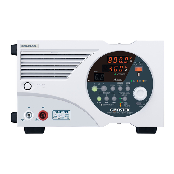
GETTING STARTED Appearance Front Panel (PSB-2400L2 shown) PSB- 2400L 2 OUTPUT ON / OFF MENU CH 1 CH 2 OFF TIMER DISP CH 1 DELAY CH 2 Hi - ( L Type ONLY ) CHECK DISP POWER MENU ENTER PRESET FAST/ LOCK(3s) / LOCAL MAX 400W... - Page 18 PSB-2000 Series User Manual Front Panel (PSB-2400H shown) PSB - 2400 H OUTPUT ON / OFF MENU OFF TIMER Hi - ( L Type ONLY ) CHECK DISP POWER MENU ENTER PRESET FAST/ LOCK(3s) / LOCAL FAST LOCK SEQUENCE REMOTE...
- Page 19 GETTING STARTED Item Description This is a ventilation grill for for cooling the Front grill internal circuits. It is detachable and has a dust filter inside. Clean the filter periodically. See page 143. Detachable. If the unit is mounted in a rack and Rubber feet the feet are not needed, they may be removed.
- Page 20 PSB-2000 Series User Manual Panel Operation Unit PSB-2400L, PSB-2800L PSB- 2400L2 PSB-2400H, PSB-2800H Type Description Address no., Normal Sequence Menu Tracking operation operation Step no., Number of Menu No. is “Ab” is cycle no., displayed. steps or displayed. displayed. Menu no.
- Page 21 GETTING STARTED Voltage LED Normal Sequence Menu Alarm (7-segment) operation operation Voltage or Cycle No. is Set parameter OVP, OCP, power is displayed. is displayed. HARD or displayed. OHP is displayed. The ―W‖ LED on the right of the 7-segment LED is lit in the power display state.
- Page 22 PSB-2000 Series User Manual Used to select the functions and change the 13 Rotary values. encoder Used for setting the voltage. Press the key and 14 V key (green) rotate the encoder to change the set value. If the A...
- Page 23 REMOTE (orange): Lit during communication through the optional interface boards. 22 ROTATE key The operating panel of the PSB-2000 series can be rotated 90 degrees so that the unit can be used in the horizontal or vertical position. Hold the encoder and rotate the panel operation unit while holding the key.
- Page 24 PSB-2000 Series User Manual Rear Panel (PSB-2400L2) CH 1 OUTPUT 400W MAX DC 80V MAX DC 40A ~100V-240V 50Hz / 60Hz 650 VA MAX CH 2 MADE IN TAIWAN OUTPUT △ AC INPUT 400W MAX DC 80V MAX DC 40A...
-
Page 25: Getting Started
GETTING STARTED Rear Panel (PSB-2800H) CAUTION OUTPUT 400W △ MAX DC 800V AC INPUT MAX DC MADE IN TAIWAN Rear Panel (PSB-2800LS) CH 1 OUTPUT 400W MAX DC 80V MAX DC 40A ~100V-240V 50Hz / 60Hz 650 VA MAX MADE IN TAIWAN △... - Page 26 25 Sensing sensing point. These terminals are short-circuited terminals before shipment to select internal sensing. The Output of the PSB-2000 series power supply 26 Rear output terminals unit is also output through these terminals. The type of rear panel output terminal varies depending on the model.
- Page 27 GETTING STARTED This connector is used for parallel and serial 27 J1 control control for master/slave operation. The optional signal input connector frame link cables must be used with this connector. This connector is used for parallel and serial 28 J2 control control for master/slave operation.
- Page 28 PSB-2000 Series User Manual Pin assignment of the J3 External Control Connector (PSB-2400L, 2800L, 2400L2, 2800LS) Pin No. Signal name Function COM for pins 2, 3 and 4. CH2 STATUS COM (COM for 2, 3 & 4) CH2 ALARM OUT Open collector output. When the alarm is output for channel 2 then this pin is pulled low.
- Page 29 GETTING STARTED Constant-current control input pin for CH2 EXT CC channel 2. CONTROL IN In the external voltage control mode, an external voltage of 0V to 10V can be used to control the ouput current from 0A to the rated output current. In the external resistance control mode, an external reistance of 0kΩ...
- Page 30 PSB-2000 Series User Manual COM pin for channel 2. Connected with CH2 COM the negative output terminal of channel Constant-voltage control input pin for CH1 EXT CV the channel 1. CONTROL IN In the external voltage control mode, an external voltage of 0V to 10V can be used to control the output voltage from 0V to the rated output voltage.
- Page 31 GETTING STARTED Output current monitor pin for channel CH1 EXT A MON Outputs approx. 0V to 10V to represent 0 to the rated output current. COM pin for channel 1. CH1 COM Connected with the negative output terminal of channel 1. Causes the alarm state to be triggered CH1 EXT ALARM when short-circuited with the CH1...
- Page 32 PSB-2000 Series User Manual Pin assignment of J3 external control connector (PSB-2400H, 2800H) Pin No. Signal name Function Constant-voltage control input pin. EXT CV CONTROL In the external voltage control mode, an external voltage of 0V to 10V can be used to control the output voltage from 0V to 800V.
- Page 33 GETTING STARTED Output current monitor pin EXT A MON OUT Outputs approx. 0V to 10V to represent the outuput current from 0A to 3A(2400H) or 6A(2800H). Connected with the negative output terminal. Trigger the alarm state when short- EXT ALARM IN circuited with the COM pin.
-
Page 34: Operation
PSB-2000 Series User Manual PERATION This chapter describes the start up procedures and the preparation that is necessary before operating the DC power supply. Connecting the AC Power Cable Make sure that the power source is shut off. Introduction ... - Page 35 OPERATION current in order to prevent a fire. The current capacity of the cables should be higher still if the cables are twisted to reduce noise or to avoid malfunctioning. Be careful of the temperature! Connecting to the Rear Output Terminals (PSB-2400L, 2800L, 2400L2, 2800LS) 1.
- Page 36 PSB-2000 Series User Manual Fig. Connection Terminal block with Rear Output Terminals Bolt (M6) Washer Output terminal bar Connect the cables using the bolts supplied with the Note power supply as shown above. If different bolts are used, they may contact the protective cover or interfere with the protective cover.
- Page 37 OPERATION Fig. Positive Grounding Connection Connect with this screw 4. Sandwich the output terminals and the load cables from above and below with the rear output terminal protective covers, as shown below. Drive the screw into the protective covers at the center. Fig.
- Page 38 PSB-2000 Series User Manual The rear output terminals have M6 holes and M3 (tapped) holes. Be sure to use the M6 holes to connect the load. Noise at the load end may be reduced by twisting the load cables or connecting a film capacitor (high-frequency, low-impedance (several μF) and an electrolytic capacitor (several...
- Page 39 OPERATION Noise at the load end may be reduced by twisting CAUTION the cables to the load or connecting a film capacitor (low impedance, high-frequency, several μF) and an electrolytic capacitor (several hundred μF) to the load end. Fig. Connection with Rear Output Terminals マイナスドライバー等...
- Page 40 PSB-2000 Series User Manual The front and rear output terminals are CAUTION electrically connected internally. Terminals that are NOT in use still carry output voltage. Be careful not to touch the terminals. Failure to heed this warning may result in electric shock.
- Page 41 OPERATION Connection with the Front Output Terminals (PSB-2400L, 2800L, 2400L2, 2800LS) 1. Turn on the unit using the POWER switch. Procedure 2. Connect crimped lug terminals to the ends of the load cables. Fix the load cables firmly to eliminate loose connections from the front output terminals and load cables.
- Page 42 PSB-2000 Series User Manual Assembling and Connecting the Front Output Terminal Plugs (PSB-2400H, 2800H) 1. Insert the cable (load line) into the plug. Procedure 2. Use a 1.5 mm hex key to fasten the 2 screws. 3. Insert the cover into the plug and make sure it hooks into place (completion image).
-
Page 43: Operation Ranges (Psb-2400L, 2800L, 2400L2, 2800Ls)
OPERATION Operation Ranges (PSB-2400L, 2800L, 2400L2, 2800LS) The PSB-2000 series power supply units offer Introduction wider voltage and current range settings, within the rated power envelope, than our traditional models. Voltage setting range: 0V to 80V (All models) Current setting range: 0A to 40A (PSB-2400L &... -
Page 44: Operation Ranges (Psb-2400H, 2800H)
PSB-2000 Series User Manual Operation Ranges (PSB-2400H, 2800H) Voltage setting range: 0V to 800V (All models) Current setting range: 0A to 3A (PSB-2400H) 0A to 6A (PSB-2800H) Power setting range: 0W to 400W (PSB-2400H) 0W to 800W... -
Page 45: Various Settings
OPERATION Various Settings Turning the Power On First, press the POWER switch to turn on the Introduction power. The power supply unit will show the startup screen (firmware version and models) for several seconds and then displays the last-used settings. The unit saves the last-used settings automatically Note when the power supply source is cut off or the... - Page 46 PSB-2000 Series User Manual How to Set the Current 1. Make sure that the A key is lit green. If not, Procedure press the A key to turn it on. 2. Set the current with the encoder wheel. How to Set Power 1.
- Page 47 OPERATION Fig. Power Display Voltage and Current and Power: Power: 400W and 40A 80V and 400W How to Turn the Output On Turning the output on or off using the OUTPUT Output Methods key. Turning the output on or off using the CH1 or ...
- Page 48 PSB-2000 Series User Manual The CH1 and CH2 keys are independent of each other, and it is possible to turn the output on through channel 1 or B by pressing the CH1 or CH2 key to select the corresponding channel.
- Page 49 OPERATION How to Display the Setting Value When the Output is On Output methods The power supply unit displays the output value when the output is on. Press the ENTER/ CHECK key when the output is on to switch the display to the setting value.
- Page 50 PSB-2000 Series User Manual How to Rotate the Display Panel 90 Degrees for Vertical Installation The display panel on the PSB-2000 series can be rotated 90 degrees so that the unit can be operated comfortably in either the horizontal or vertical orientations.
- Page 51 OPERATION How to Disable Panel Operations (Key Lock Function) It is possible to disable the front panel keys by Operation pressing the FAST/LOCK(3s)/LOCAL key on the left of the encoder. Hold this key for three or more seconds to lock the panel keys. The keys are locked when the LED beside the key turns red.
-
Page 52: Menu Key Functions
PSB-2000 Series User Manual Menu Key Functions Every press of the MENU key changes the menu Introduction numbers: PSB-2400L, 2800L, 2800LS: MENU Option ―01‖ to ―07‖. PSB-2400L2: MENU Option ―01‖ to ―09‖. PSB-2400H, 2800H: MENU Option ―01‖ to ―06‖. - Page 53 OPERATION The diagram below can be used as a reference for the menu operations in the following pages: Voltage LED Current LED 2 digit LED for displaying the number of cycles, step No., and menu No. 1. Press the MENU key until an intended function General Setting Procedure number is displayed.
- Page 54 PSB-2000 Series User Manual Preset Off timer External (voltage/resistance) Sequence External (On/Off) Delay Tracking External Preset Tracking (voltage/resistance) External (On/Off) Off timer Delay Delay (PSB-L Series Only) Sequence Off timer Sequence External Tracking (voltage/resistance) External (PSB-L Series Only) (On/Off)
- Page 55 OPERATION Preset Function Menu Item: 01(All Models) This function saves settings to one of the three Introduction PRESET keys. The settings shown below may be preset. Note that any other settings/values may not be saved. Set voltage Set current ...
- Page 56 OVP/OCP function Menu Item: 02 (All Models) OVP: (Over Voltage Protection) Introduction The OVP function turns off the output when the output voltage of the PSB-2000 series exceeds the preset OVP value. Model Setting Range Resolution PSB-2400L 1.0V to 84.0V 0.1V...
- Page 57 OPERATION 1. Press the MENU key until menu number ―02‖ is Procedure displayed. 2. Press the ENTER/ CHECK key to toggle between the OVP and OCP setting displays. On the PSB- 2400L2, the OVP and OCP settings for channel 1 appear first, followed by channel 2 next. OVP setting OCP setting →...
- Page 58 PSB-2000 Series User Manual Hi-Ω- Function Menu Item: 03 (PSB-L Series Only) The PSB-2000 series power supplies have filter Introduction capacitors connected to the output. The PSB-L power supplies also have a bleeder circuit to discharge these capacitors to a safe level when the output is turned off.
- Page 59 OPERATION Hi-Ω Off Hi-Ω On 3. Press the ENTER / CHECK key to confirm the setting. The Hi-Ω LED in the center of the panel turns ○ OFF TIMER ○ DELAY ● Hi-Ω 4. Next, set the time limit for when the bleeder circuits are turned back on with the encoder wheel.
- Page 60 PSB-2000 Series User Manual When the Hi-Ω function is activated, the output CAUTION terminals of the power supply unit keep on carrying voltage even after the output is turned off. The Hi-Ω LED will blink when Hi-Ω function is still active as the internal capacitors remain charged.
- Page 61 OPERATION Off Timer Function Menu Item: 04(PSB-L Series), 03(PSB-H Series) This function turns the output off automatically after Introduction a set amount of time. The timer can be set in ten minute steps to a maximum of 99 hours, 50 minutes. 1.
- Page 62 PSB-2000 Series User Manual The timer may be set in steps of ten minutes to a maximum of 99 hours and 50 minutes. The OFF TIMER LED will blink when the remaining time is less than five minutes. The remaining time for the off-timer may be checked by pressing the ESC/DISP key while the off-timer is running.
- Page 63 002) are installed. Without an interface board installed, the sequence function is not available. Please see the PSB_Sequence_203 usermanual or the GW Instek website for more information on how to program sequences. The following describes how to view steps in a...
- Page 64 PSB-2000 Series User Manual If the output is active at the end of the program as CAUTION shown in the figure above, the power supply output will remain at the level of the last step even after the completion of the sequence operation.
- Page 65 OPERATION ○ ○ ○ ―●SEQUENCE― 4. Next, set the Start Step number with the encoder wheel. Press the ENTER / CHECK key to confirm. The setting range is from 0 to 99. Example: The Start Step is set to No. ―00‖. 5.
- Page 66 Voltage This function allows you to control the voltage of the PSB-2000 series power supply unit by applying an external voltage to the unit. An external voltage of 0V to 10V can be used to control the output voltage from ~0V to the rated output voltage.
- Page 67 OPERATION of the PSB-2000 series power supply unit by connecting an external resistance to the unit. An external resistance of 0Ω to 10kΩ can be used to control the output current from ~0A to the rated output current. The PSB-2000 series power supply unit is...
- Page 68 PSB-2000 Series User Manual Controlling constant voltage Controlling constant voltage from the front panel using external control Controlling constant current Controlling constant current from the front panel using external control 4. Finally, press the ENTER / CHECK key to validate the settings.
- Page 69 OPERATION 1. Press the MENU key until menu number Procedure ―07‖(PSB-L) or ―06‖(PSB-H) is displayed. 2. Press the ENTER / CHECK key to enter the external output On/Off control setting mode. 3. Select On or Off with the encoder wheel, and press the ENTER / CHECK key again to confirm...
- Page 70 PSB-2000 Series User Manual Delay Function Menu Item: 08 (PSB-L2) The delay function is available on the dual channel Introduction model (PSB-2400L2) only. It adds a rise and fall delay time to the output of channel 2 for a specified amount of time (in seconds) from a reference point (output of channel 1).
- Page 71 OPERATION 3. Press the ENTER / CHECK key to confirm the setting. The DELAY LED in the center of the panel turns ○ OFF TIMER ● DELAY ○ Hi-Ω 4. Set the rise delay time with the encoder wheel. When a positive time is set, the output of channel 2 is delayed with respect to channel 1.
- Page 72 PSB-2000 Series User Manual Tracking Function Menu Item: 09 (PSB-L2) The tracking function is available on the dual Introduction channel model (PSB-2400L2) only. When the tracking function is turned on, the output of channel 2 is made to match the output of channel 1, thus channel 2 can be said to ―track‖...
- Page 73 OPERATION menu and return to normal operation. ―Ab‖ is displayed on the MENU LED when the tracking function is activated. Example: Tracking function is activated. Master-slave function Menu Item: 10 The master-slave function allows the PSB series to operate in parallel or series (PSB-L only). For series operation a maximum of 2 PSB-L units can be used.
- Page 74 PSB-2000 Series User Manual Display for a slave unit in a Display for a slave unit in parallel connection a series connection 1. The master-slave settings can be accessed by Procedure turning on the power switch while holding the MENU key.
- Page 75 OPERATION 3. Set the total power with the encoder wheel if the unit is set as the master unit in a parallel connection. Example: Total power of 3200 W. 4. Press the ESC / DISP key to exit the settings and return to normal operation.
-
Page 76: Voltage Sense
PSB-2000 Series User Manual Voltage Sense The PSB-2000 series power supply units have an Description output voltage remote sensing function. This function eliminates influences of voltage drops between the power supply unit and load, which is caused by the contact resistance or the resistance of the load cable conductors. - Page 77 OPERATION firmly. Approximately 1mA of current flows through the NOTE sensing wires at the rated output voltage. Use AWG 26 to 18 wires as the sensing wires. Fig. Remote +OUTPUT Sensing Connection (PSB-L) -OUTPUT Shielded cable or Twisted pair wires +...
-
Page 78: External Control Functions
The following connectors are supplied with the Description power supply for external control. 1. XG5M-2635-N (manufactured by OMRON Procedure Corporation) (For all PSB-2000 series) This section describes how to assemble the external control connector Assembling the XG5M-2635-N Connector 1. Remove the contacts from the housing. - Page 79 Output Voltage Monitor and Output Current Monitor It is possible to monitor the output voltage and Introduction output current of the PSB-2000 series power supply unit using the J3 external control connector. This section describes how to monitor the output voltage and output current of the dual channel model (PSB-2400L2).
- Page 80 PSB-2000 Series User Manual The internal impedance of the voltage and current NOTE monitoring circuits are approximately 1kΩ. Be careful not draw over 1mA through the monitoring circuits. 1. Voltage monitor Procedure CH1: Pins 17 and 16 (COM), CH2: Pins 8 and 7 (COM) 2.
- Page 81 OPERATION Constant-Voltage (CV) Control with External Voltage or Resistance The output voltage can be controlled by an Introduction external voltage or resistance through the J3 external connection (EXT CONT) on the rear panel if external control is selected. The negative side of the external voltage is CAUTION connected with the negative output terminal of the power supply unit.
- Page 82 PSB-2000 Series User Manual Fig.External EXT CONT (J3) Voltage/ 0Ω ~ ~ External 10kΩ Resistance control Control Terminal(CV) Negative output ※ Use a shielded cable or twisted terminal of CH1 pair wires for this control. EXT CONT (J3) 0Ω ~...
- Page 83 OPERATION Constant-Current (CC) Control with External Voltage or Resistance The current output can be controlled using an Introduction external voltage or external resistance through the connector J3 (EXT CONT) on the rear panel if external control is selected. External Resistance and External Voltage Control Pins for current control: CH1: Pins 15 and 16 (COM) CH2: Pins 6 and 7 (COM)
- Page 84 PSB-2000 Series User Manual Output ON/OFF with External Contacts The output can be turned on or off using external Introduction contact switches if the external control function is activated. External Control Pins for Output ON/OFF control: CH1: Pins 21 and 22 (COM)
- Page 85 OPERATION Alarm Function using External Contacts An external contact switch can force the PSB-L Introduction into the alarm state. When in the alarm state, the output is turned off and ―HARD‖ is displayed on the LED display. Remove the input power or turn off the power from the POWER switch to cancel the alarm state.
- Page 86 PSB-2000 Series User Manual Status Signals (CV, CC & ALARM) Constant-Voltage (CV) Status Signal Introduction This status signal goes low when the PSB-2000 series power supply unit enters the constant- voltage (CV) status. Constant-Current (CC) Status Signal This status signal goes low when the PSB-2000 series power supply unit enters the constant- current (CC) status.
- Page 87 OPERATION Fig. Status Pins EXT CONT (J3) EXT CONT (J3) ALARM ALARM Inside of CH1 status CH2 status PSB-2000 Series Fig. Photocoupler current Internal current I=1mA or less ※ Select and use proper voltage or resistance so that the open collector current does not exceed 1mA.
-
Page 88: Using The Sequence Function
The PSB_Sequence_203 software is used to create a program in advance via the optional interface board. See the Sequence Function section on page 61 for details. The PSB_Sequence_203 software can be downloaded at the GW Instek website. 1. Write a sequence program through the Procedure interface board. - Page 89 OPERATION OUTPUT Ends the sequence operation. The OUTPUT key does not the start sequence CAUTION operation. Use the PRESET 1 ( ) key to start the sequence operation. Even if the sequence function is activated and the ―● SEQUENCE LED‖ is lit, the sequence operation will not start unless the PRESET 1 ( ) key is pressed.
- Page 90 PSB-2000 Series User Manual the sequence operation partway, press the OUTPUT key or deactivate the sequence function as shown in the Section ―Sequence Function‖(page 61).
-
Page 91: Other Functions
THER FUNCTIONS Display in Alarm Status Description When the PSB-2000 series power supply unit enters an alarm state or if the alarm state is manually set using the external control connector (see page 83), an alarm code is shown on the display. The alarm code will indicate what type of alarm has been triggered. - Page 92 PSB-2000 Series User Manual This alarm code is displayed if the output current (2) OCP alarm exceeds the preset OCP value. The OHP alarm is displayed if the temperature at (3) OHP alarm an internal detection point exceeds a set temperature.
-
Page 93: Frame Link Controlled Parallel Operation (Excluding Psb-2400L2)
OTHER FUNCTIONS ALARM connector are shorted. For details, see page 83. PSB-L Only. Frame Link Controlled Parallel Operation (excluding PSB-2400L2) Description The PSB Series power supply units are capable of frame link controlled parallel operation of up to four units(PSB-L), or up to 2 units (PSB-H) including the master unit. - Page 94 PSB-2000 Series User Manual CAUTION Improper wiring or settings may cause failures. Recheck the settings before starting frame control operation. If the load cables of a slave unit are disconnected, excessive voltage is applied to the slave unit instantaneously and a ―HArd‖ alarm occurs.
-
Page 95: Frame Link Controlled Series Operation (Excluding Psb-2400L2, Psb-H Series)
OTHER FUNCTIONS Frame Link Controlled Series Operation (excluding PSB-2400L2, PSB-H series) Description The PSB-L series power supply (exlcluding the PSB-2400L2) units are capable of frame link controlled series operation of up to two units, including the master unit. When performing series operation using master units, the slave unit should be set properly in advance, see the Master-slave function chapter on page 71. -
Page 96: Power Extension Using Psb-2800Ls (Parallel Connection Only)
PSB-2000 Series User Manual Power Extension using PSB-2800LS (Parallel Connection Only) The PSB-2800LS (booster unit) is especially Description designed to boost the power capacity when used in parallel. It is possible to increase the output up to a maximum of 3200W when used in parallel with a PSB-2800L as the master unit). -
Page 97: Using The Psb-007 Extension Kits
OTHER FUNCTIONS Fig. Connection Example for Horizontal Installation Fig. Connection Example for Vertical Installation Using the PSB-007 Extension kits The PSB-007 extension kits allow master units to be Description physically connected to slave units. The extension kits can be used horizontally or vertically. Note that the PSB-2800LS cannot be used for series NOTE operation. - Page 98 PSB-2000 Series User Manual How to Connect the Units Vertically Remove the rubber feet from the bottom of Steps unit A. (Keep the removed rubber feet and screws with care not to lose them.) Fix the joint kit (PSB-007) to the top panel of unit B with the flat countersunk head screws supplied with the kit.
- Page 99 OTHER FUNCTIONS How to Connect the Units Horizontally Remove the rubber feet from the side of unit Steps B. (Keep the removed rubber feet and screws with care not to lose them.) Fix the joint kit (PSB-007) to the side of the unit A with the flat countersunk head screws supplied with the kit.
- Page 100 PSB-2000 Series User Manual Bus Bar Connection Fig. Bus Bar Connections to Fix the Output Terminals Parallel connection kit for Horizontal installation PSB-003 Parallel connection kit for vertical installation PSB-004 Terminal block Screw(M6) Washer Output terminal bar Bus bar ※ Pay attention to the positional relationship...
-
Page 101: External Control
EXTERNAL CONTROL XTERNAL CONTROL Remote Control The PSB-2000 series power supplies can be Description controlled from a PC or sequencer when one of the optional interface boards are installed. Two types of interface boards are available: PSB-001 (GPIB) and PSB-002 (RS-232C and USB). A maximum of ten units to be connected together with the local bus connection, with one unit as a master unit. -
Page 102: Interface Connectors
PSB-2000 Series User Manual Interface Connectors USB connector RS-232 connecter Local bus connecter GP-IB connector Fig. Diagram of the Interface Boards PSB-001 Specifications (optional) GPIB Conforms to IEEE488-1978. Specifications Interface functions SH1, AH1, T6, L4, SR1, RL1, PR0, DC1, DT0, C0, &... -
Page 103: Specifications (Standard)
EXTERNAL CONTROL Connector type RJ-11 (6-pin modular) Pin 2 (D+), pin 3 (D-) Applicable cable Modular cable: GRJ-1101 (500mm 6P6C RJ11) Q’ty of connectable units A maximum of 10 units can be connected in a daisy chain configuration. Terminator The terminator is built-in. It may be turned on or off with a jumper pin. -
Page 104: Connection Methods
Connection Methods The following shows an example of connecting Description several PSB-2000 series power supply units through the local bus. Fig. Local Bus PSB 2000 + PSB-001 or PSB-002 Windows GPIB or USB... - Page 105 EXTERNAL CONTROL When connecting units together using the local bus connection, any of the local bus ports on the interface board can be used as the input or output. Use the shortest modular cables possible to connect each unit. Terminate the start and end of the daisy- chain-connected units by shorting CN2 jumper pins on the interface boards with the shorting connectors...
-
Page 106: Connection Cables
PSB-2000 Series User Manual Connection Cables Use the proprietary modular cables for the local Procedure bus connection (GRJ-1101). Use standard GPIB cables for the GPIB connections. Use USB cables (applicable for Full Speed USB or greater) for the USB connections. -
Page 107: Address Setting
EXTERNAL CONTROL Address Setting The interface has two addresses: Personal Description Computer Address, and System Address. The type of address that is used depends on whether the unit is the master connected to a PC or a slave unit connected over the local bus. If the System Address is set to 1, then that unit is designated as the master unit. - Page 108 PSB-2000 Series User Manual 1. Turn on the unit while holding the A key to Procedure set the System Address and/or Personal Computer Address. The model name and version data are displayed first, and then the interface type is displayed. After this, the System Address may be set .
- Page 109 EXTERNAL CONTROL The unit saves the System Address and Personal Computer Address in non-volitile memory. The System Address and Personal Computer Address will remain saved even if the power to the unit is turned off. Personal Computer Address 1 to 30 (maximum of fourteen units through GPIB Windows PSB 2000 + PSB-0001 PSB 2000 + PSB-0001...
-
Page 110: Using The Interface Boards
PSB-2000 Series User Manual Using the Interface Boards Using the GPIB interface All GPIB operations have been tested using a Description NATIONAL INSTRUMENTS GPIB controller and sample programs. All interface cards conforming to the IEEE488 standard should be compatible with the PSB-001 interface board. - Page 111 EXTERNAL CONTROL Using the USB interface You may use the USB port of your Personal Description computer for communication through the USB interface. Microsoft Windows 98SE, 2000, XP to Windows 8* may be used. To use the USB interface, it is necessary to install ...
- Page 112 PSB-2000 Series User Manual Using the RS-232C Interface The serial port on a PC or sequencer can be used Description for communication through the RS232C interface. The interface uses CTS-RTS for flow control. Please note that with this type of...
-
Page 113: Communication Commands
EXTERNAL CONTROL Communication Commands Every communication command consists of Description general alphanumeric characters and symbols and a header, which is the abbreviation of a function. Parameters can be either an integer (NR1) or a floating point number with decimal places (NR2). -
Page 114: Command List
PSB-2000 Series User Manual An error occurs if a command causing a conflicting operation is sent while the sequence, tracking or external control function is working. Command List Category Set item Command Query Page Function Output voltage :VOLT :VOLT? - Page 115 EXTERNAL CONTROL Model inquiry *IDN? ESR query *ESR? Event enable *ESE *ESE? STB query *STB? SRQ enable *SRE *SRE? Common Clear *CLS Reset *RST Completion *OPC *OPC? Wait for *WAI completion Local :ADDR Extension communication Remote mode :REMOTE :REMOTE? Output Voltage Setting (:VOLT) This command sets or inquires about the output voltage.
- Page 116 PSB-2000 Series User Manual OVP Setting (:VOLT:PROT) This command sets or inquires about the OVP (over-voltage protection) value. Setting :VOLT:PROT <value> Sets the OVP value of a single channel model. :VOLT:PROT:A <value> Sets the OVP value of CH1. :VOLT:PROT:B <value>...
- Page 117 EXTERNAL CONTROL The <value> range for single-unit operation is as shown below: PSB-2400L & PSB-2400L2: 0.00 to 41.00 PSB-2800L: 0.00 to 82.00 PSB-2400H: 0.00 to 3.07 PSB-2800H: 0.00 to 6.15 Two decimal places are valid. The setting range changes when the power supplies are used in parallel.
- Page 118 PSB-2000 Series User Manual The <value> range in single-unit operation is as shown below: PSB-2400L & PSB-2400L2: 1.00 to 42.00 PSB-2800L: 1.00 to 84.00 PSB-2400H: 0.10 to 3.15 PSB-2800H: 0.10 to 6.30 Two decimal places are valid. The setting range changes when the power supplies are used in parallel.
- Page 119 EXTERNAL CONTROL Inquires about the set output power of a single channel model. :POW:A? Inquires about the set output power of CH1. :POW:B? Inquires about the set output power of CH2. Response example Indicates that the set output power is 100W. Remark When the tracking mode is on, setting CH1 will affect CH2.
- Page 120 PSB-2000 Series User Manual Hi-Ω ON/OFF(:CONF:HIZ) This command turns on or off the Hi-Ω function. Only applicable to the PSB-L series only. Setting :CONF:HIZ <value> <value> is as shown below: 1: Hi-Ω On 0: Hi-Ω Off Application :CONF:HIZ 1 example Activates the Hi-Ω...
- Page 121 EXTERNAL CONTROL <value> is as shown below: 1: CH1 voltage + current display 2: CH1 voltage + power display 3: CH1 power + current display 4: CH2 voltage + current display 5: CH2 voltage + power display 6: CH2 power + current display 7: Sequence or Off Timer display For a single channel model, use the values 1 to 3 or 7 to specify a display mode.
- Page 122 PSB-2000 Series User Manual External Control Setting (:EXT:MOD) This command sets the external control mode. Setting :EXT:MOD <value> <value> is as shown below: 0: Settings are controlled from the front panel or via remote control. 1: External voltage control 2: External resistance control...
- Page 123 EXTERNAL CONTROL Inquires about the setting. Response example Indicates that external control of the voltage output is enabled. The query return value has the same meaning as the setting <value>. Remark This command causes an error if the sequence function is running.
- Page 124 PSB-2000 Series User Manual External Control of the Current Output ON/OFF (:EXT:CURR) This command chooses whether the external control is used to control the output current or if the front panel controls are used to control the output current. Setting :EXT:CURR <value>...
- Page 125 EXTERNAL CONTROL Response example Indicates that output On/Off with external contacts is working. The query return value has the same meaning as the setting <value>. Remark This command causes an error if the sequence function is running. Off Timer ON/OFF (:TIMER:MOD) This command activates or deactivates the Off Timer.
- Page 126 PSB-2000 Series User Manual Delay Function ON/OFF (:DELAY:MOD) This command activates or deactivates the delay function. This function only applies to the PSB-2400L2. Setting :DELAY:MOD <value> <value> is as shown below: 0: Deactivates the delay function. (Normal) 1: Activates the delay function.
- Page 127 EXTERNAL CONTROL Delay Fall Time Setting (:DELAY:FALL) This command sets or inquires about the delay time for turning off output. Setting :DELAY:FALL <value> The <value> range is from -9.99 to +10.00 seconds. Application :DELAY:FALL 0.3 example Sets the delay time for turning off output to 0.3 second. Query :DELAY:FALL? Inquires about the setting.
- Page 128 PSB-2000 Series User Manual Preset Recall (:PRES:CALL) This command recalls and inquires about preset data. Setting :PRES:CALL <value> <value> is as shown below: 0: Cancels preset. 1: Calls PRESET 1 data. 2: Calls PRESET 2 data. 3: Calls PRESET 3 data.
- Page 129 EXTERNAL CONTROL Sequence Mode Setting (:SEQ:MOD) This command controls a sequence operation. It can start, stop or pause a sequence. Setting :SEQ:MOD <value> <value> is as shown below: 0: Stops sequence operation. 1: Pause sequence operation – Waits for start. 2: Runs sequence operation (Executes sequence).
- Page 130 PSB-2000 Series User Manual Sequence Start Step Setting (:SEQ:START) This command specifies which step to start from when running a sequence. Setting :SEQ:START<value> The <value> range is from 0 to 99. Application :SEQ:START2 example Sets the sequence to start from step no. 2.
- Page 131 Remark PSB_Sequence_203 software is available. Use it for setting The application software for sequence operation may be downloaded from the GW Instek website. Model Inquiry (*IDN?) This command returns the company name, model name, serial number and version number. Setting None.
- Page 132 PSB-2000 Series User Manual Standard Event Status Register Inquiry (*ESR?) The function of this command is described in the ―Standard Event Status Register‖ in the following section. Standard Event Status Enable Register Setting (*ESE) The function of this command is described in ―Standard Event Status Enable register‖...
- Page 133 EXTERNAL CONTROL Command Completion (*OPC) This command sets bit 0 of the standard event status register (ESR) when all current overlapped commands have been processed. Setting *OPC Sets bit 0 of the ESR when all current overlapped commands are complete. A SRQ is generated depending on the status of the ESE register and SRE register.
- Page 134 PSB-2000 Series User Manual after completion of communication with the local bus. Remote/Local Setting (:REMOTE) This command sets or inquires about the remote/local status. Setting :REMOTE <value> <value> is as shown below: 0: Local status (Normal manual operation) 1: Remote status 2: Local lockout remote status (Cannot return to the local status through key operation.)
-
Page 135: Registers
EXTERNAL CONTROL Registers The PSB power supply unit has registers that Introduction conform to the status reporting specified in IEEE488.2. Standard Event Status Event Enable (ESR) (ESE) Power On User Request Command Error Execution Error Device Dependant Error Query Error Not USED Operation Complete Standard Event Summary... - Page 136 PSB-2000 Series User Manual Status Byte Register (STB, SRE) Initial STB Initial SRE Data Item Description value value Unused. Service request Message summary Standard event summary Output message available Unused. Unused. LERR Local bus error Local bus Time out Each bit is masked when it is set to ―0‖. (0 is the Summary default setting.) A bit is not longer masked when...
- Page 137 EXTERNAL CONTROL Enables the MAV and ESB bits since the value of 48 ( 00110000 in binary) sets bit 4(MAV) and 5(ESB). Query command *SRE? Response example The masking value set with this command remains valid until the setting is changed or the power is turned off.
- Page 138 PSB-2000 Series User Manual Item Description *ESE Sets or inquires about the standard event status enable register. Setting command *ESE<value> The <value> range is from 0 to 255. Application example *ESE 48 Enables the CME (bit 5) and EXE (bit 4) of the Event Status register.
-
Page 139: Status Byte Register
EXTERNAL CONTROL (SRE) is set 1 at this time, bit 6 (MSS) of the status byte register is set to 1 and a service request (SRQ) is generated. Bit 5 Standard event status register summary Bit 4 Message available Bit 1 LERR Local bus execution error Bit 0... - Page 140 PSB-2000 Series User Manual When receiving the *CLS command, the PSB 2000 series power supply unit clears the standard event register and the status byte register. When MAV occurs. The MAV bit is cleared when all the data is read out from the output queue.
- Page 141 EXTERNAL CONTROL The GPIB buffer, output queue and input queued commands are cleared. The interface status (specified talker or listener status) is cleared. The SRQ and status byte register are cleared. The remote status and LLO (local lock out) ...
- Page 142 PSB-2000 Series User Manual When power is turned on again, the statuses are as Turning on power shown below: again The specified talker or listener status is cleared. The GPIB buffer, output queue and input queued commands are cleared.
- Page 143 EXTERNAL CONTROL Remote/Local Function The remote/local function is controlled by the Introduction system controller and with the FAST key on the PSB 2000 series power supply unit. (This key serves as the FAST, LOCK and LOCAL keys.) The PSB 2000 series power supply unit always resides in the local, remote, or remote with local lockout state.
- Page 144 PSB-2000 Series User Manual Responses to Multi-Line Message Commands The table below shows the types of multi-line Introduction message commands and the responses to the commands. Type Name Description Response Universal Clears the GP-IB buffer. commands Establishes the serial polling state.
-
Page 145: Appendix
APPENDIX PPENDIX Trouble Shooting This section shows some possible problems that Overview may arise and the solutions to some of these problems. Most problems may be solved by rechecking connections, settings or some other simple solution. Contact your nearest distributor if problems are not eliminated or improved using the trouble shooting guide. - Page 146 PSB-2000 Series User Manual current control with external voltage or resistance.” ・On/Off with the external ・See page 82, “Output On/Off contacts is selected. with external contacts”. ・The channel output key is not ・See page 45, “How to output”. selected or an incorrect channel is selected for output.
-
Page 147: Maintenance
APPENDIX Maintenance The PSB Series power supply unit employs a fan Introduction for forced cooling. Clean the dust filter inside the front grill periodically to maintain the cooling efficiency. Pull the front grill while pressing the notch in the upper part to detach the grill. Clean the filter with water. - Page 148 PSB-2000 Series User Manual PSB-2800LS PSB-2800LS Pull frontward while pressing here. Dust filter Front grill...
-
Page 149: Dimensions
APPENDIX Dimensions PSB--2400L, PSB-2400L2, PSB-2800L 12.8 35.7... - Page 150 PSB-2000 Series User Manual PSB-2800LS 35.7 Φ6.5 82.7...
- Page 151 APPENDIX PSB-2400H, PSB-2800H 12.5...
-
Page 152: Psb-2000L Series Specifications
PSB-2000 Series User Manual PSB-2000L Series Specifications Output Model PSB-2400L PSB-2800L PSB-2400L2 PSB-2800LS Rated output voltage 80.00V 80.00V 80.00V×2CH 80.00V Setting accuracy 0.1% setting ±2 digit (23ºC ±5ºC) Resolution 10mV Display accuracy 0.2% reading ±2 digit (23ºC ±5ºC) Rated output current 40.00A... - Page 153 APPENDIX Constant-Current Characteristics Model PSB-2400L PSB-2800L PSB-2400L2 Line regulation 0.01% ±2mA of rated current Load regulation 0.02% ±3mA of rated current Ripple noise (rms) 30mA 60mA 30mA Temperature coefficient (typ.) ±100ppm/ºC (after 30-minute warming up) Constant-Power Characteristics Model PSB-2400L PSB-2800L PSB-2400L2 Line regulation 0.5% ±10W...
- Page 154 PSB-2000 Series User Manual Alarm signal output Open collector, active low. Alarm signal input Turns off the output when shorted. Compensates for a voltage drop of up to 1V (single side) Remote sensing function within the rated voltage at both ends of the power supply.
- Page 155 APPENDIX Protective functions Over-voltage protection (OVP): Stops oscillation when the output voltage exceeds 110% of Fixed rated voltage. (Output Off) Over-voltage protection (OVP): Presettable range: 1V to 84V on front panel. Variable Stops oscillation when OVP works. (Output Off) Over-current protection (OCP): Stops oscillation when output current exceeds 110% of Fixed rated current.
- Page 156 PSB-2000 Series User Manual Default Settings and Storage after Power Off Item Initial setting Storage after power off Voltage 0.00V Current 0.00A Power 410W/820W 84.00V 42.00A/84.00A Display mode CH1(V/A) Menu display Initialized when power is turned off. × Operation mode...
- Page 157 APPENDIX Parallel/Serial Operation Setting Table PSB-2400L (Part 1/2) Single Parallel 2400L 2400L x 2 2400L x 3 2400L x 4 Item 2400L + 2800L 400W 800W 1200W 1600W Voltage Setting SLOW 10mV FAST Range 0V to 82V Min. display digit 10mV Current Setting SLOW...
- Page 158 PSB-2000 Series User Manual PSB-2400L (Part 2/2) Parallel Series 2400L+ 2800L 2400L + 2400L 2400L + 2800L 2400L + 2400L Item + 2800L x 2 2000W 2400W 2800W 800W Voltage Setting SLOW 10mV FAST Range 0V to 82V Min. display digit...
- Page 159 APPENDIX PSB-2800L Single Parallel Series 2800L 2800L x 2 2800L x 3 2800L x 4 2800L + Item 2800L 800W 1600W 2400W 3200W 1600W Voltage Setting SLOW 10mV FAST Range 0V-82V Min. display 10mV digit Current Setting SLOW 10mA 100mA 90mA 80mA 10mA...
-
Page 160: Psb-2000H Series Specifications
PSB-2000 Series User Manual PSB-2000H Series Specifications Output Model PSB-2400H PSB-2800H Rated output voltage 800.0V Setting accuracy 0.1% setting ±2 digit (23ºC ±5ºC) Resolution 100mV Display accuracy 0.2% reading ±2 digit (23ºC ±5ºC) Rated output current 3.00A 6.00A Setting accuracy 0.2% setting ±2 digit (23ºC ±5ºC) - Page 161 APPENDIX Fall time (typ.) 500ms (rated load), 1000ms (no load) Temperature coefficient (typ.) ±100ppm/ºC (after 30-minute warming up) Constant-Current Characteristics Model PSB-2400H PSB-2800H Line regulation 0.05% ±10mA of rated current Load regulation 0.05% ±15mA of rated current Ripple noise (rms) 15mA 20mA Temperature coefficient (typ.)
- Page 162 PSB-2000 Series User Manual Constant-current (CC) Open collector, active low. status signal Alarm signal output Open collector, active low. Alarm signal input Turns off the output when shorted. Compensates for a voltage drop of up to 1V (single side) Remote sensing function within the rated voltage at both ends of the power supply.
- Page 163 APPENDIX Power In terminals - frame: DC500V, 30MΩ or more. Power In terminals - output terminals: DC1000V, 30MΩ or Insulation resistance more. Output terminals - frame: DC1000V, 30MΩ or more. 210mm(W)×124mm(H)×290mm(D) Outside dimensions (Projections not included.) PSB-2400H: Approx. 5kg Weight PSB-2800H: Approx.
- Page 164 PSB-2000 Series User Manual Parallel Operation Setting Table PSB-2000H Single Parallel Item 2400H 2800H 2400H x 2 2800H X 2 400W 800W 800W 1600W Voltage Setting SLOW 100mV FAST Range 0V to 820V Min. display digit 100mV Current Setting SLOW...
-
Page 165: Declaration Of Conformity
APPENDIX Declaration of Conformity GOOD WILL INSTRUMENT CO., LTD. (1) No.7-1, Jhongsing Rd., Tucheng City, Taipei County, Taiwan (2) No. 69, Lu San Road, Suzhou City (Xin Qu), Jiangsu Sheng, China declare, that the below mentioned product Type of Product: Multi-range DC Power Supply Model Number:PSB-2400L, PSB-2800L, PSB-2400L2, PSB-2800LS are herewith confirmed to comply with the requirements set out in the...
Need help?
Do you have a question about the PSB-2000 series and is the answer not in the manual?
Questions and answers