Sony PMW-EX30 Operating Instructions Manual
Solid-state memory recorder
Hide thumbs
Also See for PMW-EX30:
- Service manual (144 pages) ,
- Brochure (24 pages) ,
- Quick start manual (8 pages)
Table of Contents
Advertisement
Printed on recycled paper.
Printed on recycled paper.
Sony Corporation
Printed in Japan
Printed in Japan
Solid-State Memory
Recorder
Operating Instructions
Before operating the unit, please read this manual thoroughly
and retain it for future reference.
PMW-EX30
© 2008 Sony Corporation
3-879-701-13(1)
3879701130
Advertisement
Table of Contents

Related Manuals for Sony PMW-EX30


Summary of Contents for Sony PMW-EX30
-
Page 1: Operating Instructions
Recorder Operating Instructions Before operating the unit, please read this manual thoroughly and retain it for future reference. Printed on recycled paper. PMW-EX30 Printed on recycled paper. Sony Corporation 3879701130 © 2008 Sony Corporation Printed in Japan Printed in Japan... - Page 2 For the customers in the U.S.A. WARNING This equipment has been tested and found to comply with the limits for a To reduce the risk of fire or Class A digital device, pursuant to Part 15 of the FCC Rules. These limits are electric shock, do not designed to provide reasonable expose this apparatus to...
- Page 3 Sony Corporation, 1-7-1 Konan, l’entretien de l’appareil Minato-ku, Tokyo, Japan. qu’à un personnel qualifié. The Authorized Representative for EMC and product safety is Sony Deutschland GmbH, Hedelfinger ATTENTION Strasse 61, 70327 Stuttgart, Germany. Eviter d’exposer l’appareil à un For any service or guarantee matters égouttement ou à...
- Page 4 Flüssigkeiten gefüllten et E4 (environnement EMC contrôlé, Gegenstände, z. B. Vasen, darauf ex. studio de télévision). abgestellt werden. Le fabricant de ce produit est Sony Das Gerät nicht an Orten aufstellen, Corporation, 1-7-1 Konan, Minato-ku, z.B. in Bücherregalen oder Tokyo, Japon.
- Page 5 (kommerzieller und in beschränktem Maße industrieller Bereich), E3 (Stadtbereich im Freien) und E4 (kontrollierter EMV-Bereich, z.B. Fernsehstudio). Der Hersteller dieses Produkts ist Sony Corporation, 1-7-1 Konan, Minato-ku, Tokyo, Japan. Der autorisierte Repräsentant für EMV und Produktsicherheit ist Sony Deutschland GmbH, Hedelfinger Strasse 61, 70327 Stuttgart, Deutschland.
-
Page 6: Table Of Contents
Table of Contents Chapter 1 Overview Features .................10 Using the CD-ROM ..............13 Reading the CD-ROM manuals ........13 System requirements for using the applications .....13 Software installation ............14 Names and Functions of Parts ..........15 Front panel ...............15 Rear panel ................24 IR remote commander (supplied) ........26 Chapter 2 Preparations Starting the Unit ..............28 Connecting the unit to a power source ......28... - Page 7 Formatting ...............43 Using the IR Remote Commander (Supplied) ....44 Placing the Unit in a Vertical Position ........46 Superimposed Text Information .........46 Turning superimposed text on and off ......46 Chapter 3 Recording and Playback Recording ................47 Settings for recording .............47 Recording operation ............49 Recording shot marks .............50 Playback .................51 Settings for playback ............51...
- Page 8 timecode (Regen mode) ..........67 Synchronizing the internal timecode generator to an external timecode —External synchronization (Ext regen mode) ................67 Chapter 6 Example Connections for Various Applications Connecting External Video Monitors .........69 Operating Clips with a Computer ........71 Connecting an External Device with the HD SDI Connector ....................73 Dubbing clips ..............73 Configuring a live recording system .......74...
- Page 9 Periodic Maintenance ............97 Digital hours meter ............97 Troubleshooting ..............98 Alarm messages ............100 Error messages ..............102 About i.LINK ..............103 Specifications ...............104 MPEG-2 Video Patent Portfolio License ......107 AVC Patent Portfolio License ..........108 VC-1 Patent Portfolio License ...........108 Index ..................109 Table of Contents...
-
Page 10: Chapter 1 Overview
(35 Mbps VBR) or approx. 140 minutes in SP mode (25 Mbps CBR) on a single 32-GB SxS memory card. Equipped with two SxS The PMW-EX30 is a highly compact, high- memory card slots, the PMW-EX30 makes performance XDCAM EX... - Page 11 • COMPONENT: For output of HD and Each time a recording is started and stopped SD analog component video signals. on the PMW-EX30, the video and audio • S-VIDEO: For output of SD analog Y/C signals are recorded as one clip.
- Page 12 The half-rack size body width allows the PMW-EX30 unit to be neatly housed in a rack by, for example, placing it on top of an HDV deck or placing the two side by side. You can also use the supplied supporting feet to place the unit in a vertical position near a computer monitor or the like.
-
Page 13: Using The Cd-Rom
To read the documents State Memory Recorder” contains the pdf Do the following: files of the Operating Instructions for the PMW-EX30 (Japanese, English, French, Insert the CD-ROM in your CD-ROM German, Italian, Spanish and Chinese). drive. The CD-ROM labeled “Utility Software for... -
Page 14: Software Installation
Choose “Start”, “Control Panel” then “Add For support information on the driver, refer or Remove Programs” and specify the to the following URL: program to be deleted. http://www.sony.net/SxS-Support/ Macintosh computer XDCAM EX Clip Browsing Drop the folder of the software (default: /Application/XDCAM EX Clip Browser) Software into Trash. -
Page 15: Names And Functions Of Parts
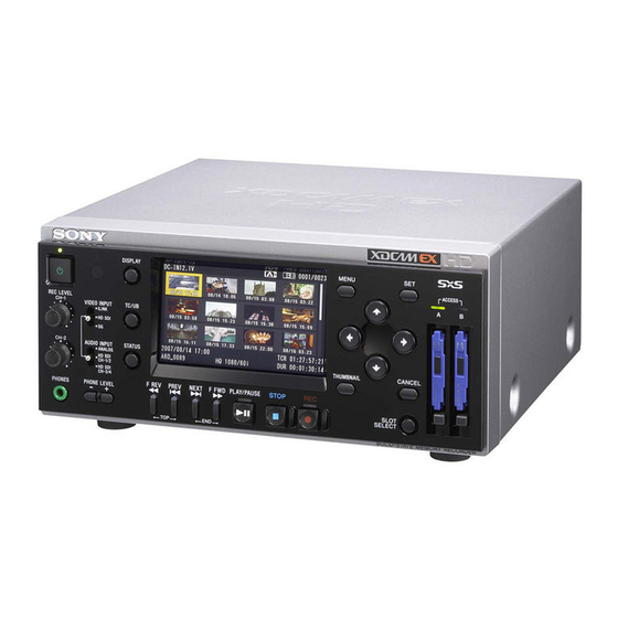
Names and Functions of Parts Front panel 1 Power button and indicator (1) 2 Infrared sensor 3 DISPLAY button 4 MENU button 5 M, m, <, , buttons 6 SET button DISPLAY MENU ACCESS REC LEVEL CH-1 TC/UB VIDEO INPUT iLINK HD SDI CH-2... -
Page 16: Display Button
1 Audio input level control section (see page 17) 2 Video/audio input selection section (see page 18) 3 LCD display (see page 18) DISPLAY MENU ACCESS REC LEVEL CH-1 TC/UB VIDEO INPUT iLINK HD SDI CH-2 AUDIO INPUT STATUS ANALOG HD SDI THUMBNAIL CANCEL... - Page 17 A Audio input level control section e <, ,, M, m buttons Use these buttons to move around the menu Press this button to show the status screens. items, to select clips in a thumbnail screen, Press it again to exit the status display. and also to set the initial timecode value and user bit data.
-
Page 18: Lcd Display
B Video/audio input selection Pressing the DISPLAY button to enable section superimposition provides text information shown in the following figure on recording, E-E, and playback pictures. Alarm/error VIDEO INPUT iLINK messages and notice/confirmation HD SDI messages (shown in 7 and 0) are displayed, if required, regardless of the 1 VIDEO INPUT switch DISPLAY button status. - Page 19 1 DC IN voltage indication 2 Operation mode 3 Media status indication 4 Time data indication 5 Video format indication (in recording/E-E mode) Clip No. and total number of clips indication (during playback) DC IN12.0V TCG 00:00:00:00 A: 25min Madia Near full HQ 1080/24P 6 Video input signal B: 50min...
- Page 20 of each card and indicated in time units of Note minutes. This unit allows setting of timecode and user bit data when an HDSDI signal or the Note internal test signal is recorded. When an HDV signal input to the HDV/DV icon appears if the memory card is connector is recorded, the timecode and write-protected.
- Page 21 A channel to monitor can be selected by Guide Functions changing the setting of “Monitor CH” (see marks page 88) in the “Audio Set” setting of the Jump to the top of the next AUDIO SET menu. During playback, also clip change the “Output CH”...
-
Page 22: Stop Button
d F FWD (fast forward) button and normal playback, press the PLAY/PAUSE button. indicator Pressing the PREV button and F REV Use this button for high-speed playback button simultaneously cues up the top of the (with audio muted) in the forward direction. first-recorded clip on the memory card Each time you press the button, the (TOP button function). - Page 23 ACCESS 1 ACCESS lamps 2 SxS memory card slots 3 EJECT button 4 SLOT SELECT button a ACCESS lamps When an SxS memory card is inserted into one of the slot, the ACCESS lamp at the slot lights in red then changes to green once the memory card is ready for use.
-
Page 24: Rear Panel
Rear panel 1 AUDIO INPUT LEVEL switch 2 AUDIO INPUT CH-1 and CH-2 connectors 3 AUDIO OUTPUT CH-1/3 and CH-2/4 connectors 4 COMPOSITE connector 5 S-VIDEO connector 6 COMPONENT connectors 7 DC IN connector 8 HDMI connector 9 HD/SD SDI OUTPUT connector 0 HD SDI INPUT connector qa USB connector ( qs HDV/DV connector... - Page 25 b AUDIO INPUT CH-1 and CH-2 f COMPONENT connectors (BNC (channels 1 and 2) connectors (phono type) jacks) Output HD analog component signals or Input analog audio signals to the CH-1 and down-converted SD analog component CH-2 connectors. Set the input level with signals from the Y, Pb/B–Y, and Pr/R–Y the AUDIO INPUT LEVEL switch to –10, connectors.
-
Page 26: Ir Remote Commander (Supplied)
i HD/SD SDI OUTPUT connector CAUTION (BNC type) When you connect the USB cable of the Outputs HDSDI signals or down-converted unit to peripheral device, use the supplied SDSDI signals. Audio signals and timecode cable to prevent malfunction due to are embedded in the SDI signals. - Page 27 1 ZOOM T/W buttons 2 SHOTMARK1 and 2 buttons PUSH SET SHOTMARK ZOOM 9 PUSH SET button 3 THUMBNAIL button 0 NEXT button THUMBNAIL SUB CLIP 4 PREV button PREV PLAY/PAUSE NEXT STOP qa STOP button 5 F REV button >...
-
Page 28: Chapter 2 Preparations
Preparations Chapter Power indicator Starting the Unit Power button VIDEO INPUT switch LCD display When you use this unit for the first time after purchasing, the initial settings are DISPLAY MENU required (see page 28). ACCESS REC LEVEL CH-1 VIDEO INPUT TC/UB iLINK HD SDI... -
Page 29: Setting The Clock
Note Setting the Clock While the initial setting display is shown, no other operation except turning the power off is permitted until you finish the setting for this display. When the initial setting display appears on the LCD display, Set the date and time of When the initial setting display is not the built-in clock, using this display. -
Page 30: Adjusting The Lcd Display
Press the M or m button to set the year Adjusting the LCD then press the < or , button. The cursor moves to the month-setting Display column. Set the month, day, hour, minute, and second in sequence in the same You can adjust the display conditions of the manner. -
Page 31: Video Format And Input/Output Signals
LCD SET Video Format and Color Cont rast Input/Output Br i ght ness 00:00 Back Light Signals The video format to be used on this unit can be set with “Video Format” of the OTHERS menu. When the unit is used for recording, it is required to input a signal conforming to the video format set on the unit. -
Page 32: Video Format And Output Signals
When “Country” is set to “NTSC Area”: HQ 1080/60i, SP 1080/60i, HQ 720/ 60P, HQ 1080/24P, HQ 1080/30P When “Country” is set to “PAL Area”: HQ 1080/50i, SP 1080/50i, HQ 720/ 50P, HQ 1080/25P Video format choices Note Video format choices vary with the It is not possible to change the video format “Country”... -
Page 33: During Playback
when any other video format setting is no signal may be output from those selected.) connectors. • When a signal containing strong jitters • When “HDMI/CMPNT/SDI Out SEL” is (such as a computer output) is input to the set to “480P (576P)”, no signal is output HDV/DV connector, output video and from the HD/SD SDI OUTPUT audio from the HD/SD SDI OUTPUT... - Page 34 Clip video format Output video format “HDMI/CMPNT/SDI Out SEL” setting 1080i/720P 1080i b) c) 480i (576i) 480P (576P) NTSC HQ 1080/60i 1080/59.94i 480/59.94i 480/59.94P SP 1080/60i (1080/49.95i) (576/49.95i) (576/50P) SP 1080/24P HQ 1080/30P 1080/29.97PsF (1080/49.95i) HQ 1080/24P 1080/ 1080/59.94i (1080/49.95i) 23.98PsF (1080/49.95i) HQ 720/60P...
-
Page 35: Time Data Handled By This Unit
The time data type indicator (see page 19) Time Data is switched between TC and UB each time you press the TC/UB button. Handled by This In recording or E-E mode Unit TCG: Timecode generated by the timecode generator UBG: User bit data generated by the timecode generator Using time data allows you to easily check During playback... -
Page 36: Handling Sxs Memory Cards
• Do not use or store SxS memory cards in Usable SxS memory cards locations that are: The following Sony SxS memory cards - Outside the specified environmental (SxS PRO or SxS-1) are recommended for ranges this unit:... -
Page 37: Inserting/Removing An Sxs Memory Card
PHONE LEVEL > SLOT card, erase it using commercial data SELECT erasure software, or physically destroy it. Sony cannot be responsible for any Card SLOT SELECT button failure to erase data completely. slots EJECT button • Clip operations may not be possible when the remaining capacity of the media is low. -
Page 38: Switching Between Sxs Memory Cards
Status indications by the ACCESS lamps Card slots A and B are accompanied by the respective ACCESS lamps to indicate their statuses. Lamp Slot statuses Lights in red Accessing the loaded SxS memory card (writing/reading data) Lights in Standby (ready for green recording or playback using the loaded SxS... -
Page 39: Formatting An Sxs Memory Card
• The SLOT SELECT button is disabled If formatting fails for a few seconds after it is pressed to A write-protected SxS memory card or switch to other media (optional SxS memory card that cannot be used with this memory card, PHU-60K/120K/120R unit will not be formatted. -
Page 40: Restoring An Sxs Memory Card
When restoration is completed, the Note completion message is displayed for three icon appears if the memory card is seconds. write-protected. If restoration fails • A write-protected SxS memory card or Replacing an SxS memory one on which an error occurred cannot be card restored. -
Page 41: Using A External Hard Disk
Using a External Hard Disk You can use an optional PHU-60K, PHU- 120K, or PHU-120R Professional Harddisk Unit with this unit. Notes • High-speed playback may not be possible Insert so that the cable extends upward. with the PHU-60K/120K/120R • When using the PHU-120R, set the mode Turn on the PHU-60K/120K/120R. -
Page 42: Checking The Remaining Time Available For Recording
If the message appears, press the M or m Checking the remaining button to select “Execute”, and press the time available for recording SET button. The remaining time is displayed in the same Notes manner as that for the SxS memory card. •... -
Page 43: Using A Media Adaptor
Format the “Memory Stick” or SDHC card Using a Media as instructed below. Adaptor To execute formatting Display the OTHERS menu and select “Format Media” (see page 95). Use of the optional MEAD-MS01 or MEAD-SD01 Media Adaptor permits you Select [Media(A)] (slot A) or to insert a “Memory Stick”... -
Page 44: Using The Ir Remote Commander (Supplied)
SDHC card with the device to be used. Before use • “Memory Stick” and Before you use the supplied IR remote are trademarks of Sony Corporation. commander for the first time, pull out the • “Memory Stick PRO-HG Duo” and insulation sheet from the battery holder. - Page 45 To replace the battery in the CAUTION IR remote commander Danger of explosion if battery is incorrectly When the lithium battery’s power falls, the replaced. IR remote commander may not work even Replace only with the same or equivalent if you press the buttons. The average type recommended by the manufacturer.
-
Page 46: Placing The Unit In A Vertical Position
Placing the Unit in Superimposed a Vertical Position Text Information You can place the unit in a vertical position Signals output from the HDMI, by using the supplied pair of supporting COMPONENT, COMPOSITE, S-VIDEO, feet. and HD/SD SDI OUTPUT connectors can contain superimposed text information, including timecode, menu settings, and alarm messages. -
Page 47: Chapter 3 Recording And Playback
Recording and Playback Chapter To set the timecode value or user bit Recording data For details on setting the timecode value or user bit data, see Chapter 5 “Setting and Recording Time Data” (page 66). This unit allows recording HDSDI signals input to the HD SDI INPUT connector and Use the VIDEO INPUT switch to HDV signals input to the HDV/DV... - Page 48 Video signal to VIDEO INPUT Audio signal to AUDIO INPUT record switch position record switch position (input signal indication on the monitor screen) HDV signals input to i.LINK (i.LINK in) 2-channel digital — audio signals the HDV/DV embedded in the connector input HDV signals HDSDI signals input...
-
Page 49: Recording Operation
Check and adjust the audio input level Connect headphones to the PHONES jack with the audio level meter on the to monitor audio being recorded. Adjust the monitor screen. volume of the headphones by pressing the PHONE LEVEL buttons. Audio input level is set to the reference level preset at the factory. -
Page 50: Recording Shot Marks
To check the status during recording Press the DISPLAY button. SHOTMARK 1 button PUSH SET For details on each indication displayed, see SHOTMARK ZOOM SHOTMARK 2 button “ LCD display” (see page 18). THUMBNAIL SUB CLIP To stop recording PREV PLAY/PAUSE NEXT STOP... -
Page 51: Playback
the volume of the headphones by pressing Playback the PHONE LEVEL buttons. Note It is not possible to play back audio The SxS memory card stores the recording recorded in Interval Recording, Frame contents as “clip”. This section explains Recording, or Slow & Quick Motion operations for playing back the clips in Recording mode on other devices. - Page 52 Press the PLAY/PAUSE button to start To insert a shot mark during playback. playback The PLAY/PAUSE indicator lights. Use the IR remote commander. To check the status during playback Set “IR Remote” (see page 93) of the Press the DISPLAY button. OTHERS menu to “On”...
-
Page 53: Chapter 4 Clip Operations
Clip Operations Chapter Playing Back Clips When this unit is started with an SxS memory card loaded, or when the THUMBNAIL button is pressed while this unit is in E-E or playback mode, a thumbnail screen appears on the monitor screen to show index frame images of the clips recorded on the memory card as thumbnails. - Page 54 The icon of the currently selected memory card is highlighted. (If the card is write-protected, a lock icon is Date and starting displayed to the left.) time of recording Current clip No./Total number of clips Cursor (yellow) DC IN 12.0V 0011 / 0300 01/JAN 10 : 53 01/JAN 11 : 53...
-
Page 55: Playing Back The Selected And Subsequent Clips
You can perform playback pause (see page DISPLAY MENU 52), high-speed playback (see page 52) and ACCESS REC LEVEL CH-1 shot-mark recording (see page 50). VIDEO INPUT TC/UB iLINK HD SDI CH-2 When playback of the last clip ends, this AUDIO INPUT STATUS ANALOG... -
Page 56: Playing Back A Clip Repeatedly
• When you press the button in fast-reverse DC IN 12.0V CLIP REPEAT 0011/0300 playback or in pause mode, the top of the JPAN0011(1) current clip is cued up, then the still 01/JAN/2008 10:53 picture is displayed. HQ 1080/24P S&Q MOTION 29/24fps •... -
Page 57: Clip Operations
For the still picture in pause mode Clip Operations (page 58) CANCEL DISP CLIP INFO You can use Clip Operation menus to OK MARK ADD operate the clips or confirm and change the SHOT MARK1 ADD SHOT MARK2 ADD subsidiary data for clips. Clip Operation EXPAND CLIP menus can be displayed in the thumbnail screen (see page 53), the EXPAND CLIP... -
Page 58: Displaying The Detailed Information Of A Clip
Clip Operation menu on the Item Function thumbnail screen SHOT To display thumbnails Pressing the SET button with the thumbnail MARK2 only of the frames with shot mark 2 recorded screen (page 53) displayed calls the Clip (see page 63) Operation menu for the clip at the cursor. -
Page 59: Adding The Ok Mark To A Clip
Image of the current clip Timecode at the recording starting point Timecode of the displayed frame Special recording information (see page 54) Recording format Date and starting time of recording Clip name OK mark (see page 54) DC IN 12.0V CL I P I NFO 0011 / 0300 JPAN0011 ( 1 ) -
Page 60: Copying A Clip
Select “Execute”, and press the SET Copying begins. button. The clip is copied with the same name to the destination SxS memory card. The OK mark is applied to the selected An execution message and an in- clip. progress bar are displayed during copying. -
Page 61: Deleting A Clip
The corresponding Clip Operation Deleting a clip menu pops up. You can delete a clip selected on the Select “EXPAND CLIP” from the Clip thumbnail screen from the SxS memory Operation menu. card. The EXPAND CLIP screen appears Select the clip you wish to delete on the for the clip in pause mode or that you thumbnail screen then press the SET selected on the thumbnail screen. - Page 62 EXPAND CLIP screen Current frame number DC IN 12.0V EXPAND CLIP 0000123 01 : 10 : 20 : 00 01 : 10 : 30 : 00 01 : 10 : 40 : 00 01 : 10 : 50 : 00 01 : 11 : 00 : 00 01 : 11 : 10 : 00 01 : 11 : 20 : 00...
-
Page 63: Displaying The Shot Mark Screen
frames as the thumbnail images on the Item Function screen. SHOT To add shot mark 2 to MARK2 ADD the selected frame (see Select a clip on the thumbnail screen. page 64) Press the SET button. SHOT To delete shot mark 1 MARK1 DEL from the selected frame The Clip Operation menu pops up. -
Page 64: Adding/Deleting Shot Marks
Clip Operation menu on the Press the SET button. SHOT MARK screen To cancel the operation When you select a frame on the SHOT Select “Cancel” and press the SET MARK screen and press the SET button, button, or press the CANCEL button. the Clip Operation menu pops up to permit you further operations. -
Page 65: Changing The Index Frame
Press the SET button. The information screen for the selected frame appears, and a confirmation To cancel the operation message is displayed below the image. Select “Cancel” and press the SET Press the SET button. button, or press the CANCEL button. To cancel the operation Changing the index frame Select “Cancel”... -
Page 66: Chapter 5 Setting And Recording Time Data
Setting and Recording Time Data Chapter To display the time data Recording LCD display Timecode and User Bit Data DISPLAY MENU ACCESS REC LEVEL CH-1 VIDEO INPUT TC/UB iLINK HD SDI CH-2 AUDIO INPUT STATUS ANALOG HD SDI THUMBNAIL CANCEL CH-1/2 HD SDI CH-3/4... -
Page 67: Recording Timecode To Continue From Previously Recorded
Press the SET button. Menu item Setting The new settings are saved in the Mode Preset memory of the unit. Free Run or Rec Note The new setting may be lost if you power 1) The internal timecode generator begins off the unit during the saving operation. - Page 68 Input an HDSDI signal to the HD SDI INPUT connector. Set the VIDEO INPUT switch to HD SDI or SG. Set “Mode” in the “Timecode” setting of the TC/UB SET menu to “Ext REGEN”. Note If timecode data is not embedded in the input signal to the HD SDI INPUT connector, the initial timecode value is that of the internal timecode.
-
Page 69: Chapter 6 Example Connections For Various Applications
Example Connections for Various Applications Chapter Squeeze: To horizontally reduce a 16:9 Connecting picture to output a 4:3 picture Letterbox: To mask the upper and lower External Video areas of a 4:3 picture to display a 16:9 picture in the center of the screen Monitors Edge Crop: To cut the both sides of a 16:9 picture to output a 4:3 picture... - Page 70 Video monitor SDI input connector Audio input connectors HDMI RGB/ VIDEO IN Y/C IN COMPONENT AUDIO OUTPUT COMPONENT COMPOSITE S-VIDEO CH-1/3, CH-2/4 AUDIO VIDEO OUTPUT INPUT OUTPUT COMPSITE S-VIDEO CH-1 CH-1/3 INPUT LEVEL (dB) COMPONENT Pb/B-Y Pr/R-Y CH-2 CH-2/4 HD SDI HD/SD SDI HDV/DV INPUT...
-
Page 71: Operating Clips With A Computer
Notes Operating Clips • When connecting the USB cable to the with a Computer computer, be careful to check the form and direction of the USB connector. • This unit and the SBAC-US10 do not work on the bus power from the computer. - Page 72 For Macintosh Drag the SxS memory card icon on the desktop to Trash. If the SxS memory card icon is located on Finder, click on the eject icon on its side. Note Do not select “Card Power Off” from the With Windows, check that the memory SxS memory card icon displayed on the card is displayed as a removable disk...
-
Page 73: Connecting An External Device With The Hd Sdi Connector
To use a nonlinear editing Connecting an system For a nonlinear editing system, optional External Device editing software that corresponds to the with the HD SDI recording formats used with this unit is required. Connector For the nonlinear editing performed via the HDV/ DV connector, see “Nonlinear editing”... -
Page 74: Configuring A Live Recording System
To perform dubbing Set the format of video and audio input signals to HDSDI on the recorder. For details on the setting, refer to the operation manual supplied with the recorder. Put the recorder into recording standby mode. Insert the SxS memory card into this unit and cue up the clip you want to dub. - Page 75 To record live materials on this unit Perform manual recording using the REC For operation method, see “Recording” (page 47). button. AUDIO To distribution system AUDIO microphones HD SDI AWS-G500 HD SDI HDSDI output connector (HFBK-HD1) HD SDI BRC-Z700W AUDIO This unit HD SDI INPUT...
-
Page 76: Connecting An External Device With The I.link Connector
Dubbing clips Connecting an This section shows an example for External Device connecting this unit and the HVR-M35 HDV Videocassette Recorder to perform with the i.LINK dubbing clips from an SxS memory card to Connector a tape. On how to use the HVR-M35, refer to the Operating Instructions supplied with the HVR-M35. -
Page 77: Recording An Input Signal From An External Device
To perform dubbing On how to use the HVR-M35, refer to the Operating Instructions supplied with the HVR-M35. Set the video format to SP 1080/60i Notes (when “Country” is set to “NTSC Area”) or SP 1080/50i (when • DVCAM signals cannot be recorded on “Country”... -
Page 78: Nonlinear Editing
To record a signal input from an Nonlinear editing external device This section shows an example for Set the video format to SP 1080/60i connecting a computer with nonlinear (when “Country” is set to “NTSC editing software installed via the HDV/ Area”) or SP 1080/50i (when DV connector, to edit clips recorded on an... - Page 79 • When making a search through pictures recorded on the memory card loaded into this unit from the computer, it may take some time until the search display is reflected on the computer. • If the current playback clip is short or the playback starting point is near the end of the clip, the i.LINK signal may be interrupted between the clip and the next...
-
Page 80: Chapter 7 Status Display
Status Display Chapter To switch the status screens Showing the Pressing the M or m button switches the screens in sequence. Status Display To clear the status display Press the STATUS button again. This unit provides a status display The status display is cleared if you press the switchable through three types of screens, MENU button to show the menu and start or allowing you to check the various settings... -
Page 81: Audio Status Screen
Audio Status Video Status Screen Screen The audio status screen displays The video status screen displays information on audio signals. information on recording and playback of video signals. AUDIO 1 / 3 CH-1 VIDEO 2 / 3 CH-2 V i deo Format : 1080/60i oo -40 0 OVER... -
Page 82: Remote/Media Status Screen
i.LINK Out: HDV/DV output status Remote/Media Displays the output status of the HDV/ DV connector (HDV, DVCAM, or off) Status Screen depending on the “i.LINK I/O Select” setting of the VIDEO SET menu. The remote/media status screen displays the status of the IR remote commander, remaining space of the media and available recording time. -
Page 83: Chapter 8 Menu Configuration And Detailed Settings
Menu Configuration and Detailed Settings Chapter Setup menu layers Overview of the Setup Menus This unit allows you to make various settings for recording and playback with setup menus on the monitor screen. For connections of an external video monitor, see “Connecting External Video Monitors”... -
Page 84: Basic Menu Operations
To set the setup menus Basic Menu Press the M or m button to move the Operations cursor to the icon of the menu you wish to set. The selectable menu items are displayed in the menu item selection This section describes the basic operations area to the right of the icon. - Page 85 Example: OTHERS menu Example OTHERS TC/UB SET All Reset Timecode Setup Data Users Bit Time Zone UTC +09:00 TC For mat : 00:00 00:00 Clock Set Language English Hours Meter Choices Displayed when there are more menu To return to the previous items beneath.
- Page 86 Select the desired value by pressing the M or m button, then press the SET button to confirm the setting. To cancel the setting, press the CANCEL button. When the SET button is pressed, the setting is changed and the new setting is displayed.
-
Page 87: Setup Menu List
Setup Menu List The functions and available settings of The default settings set at the factory are menus are listed below. shown in bold face (example: Preset). AUDIO SET menu Menu items Subitems and Description setting values Audio Input 1KHz Tone Turn the 1-kHz reference tone signal on/off Setting for audio On / Off... -
Page 88: Video Set Menu
Menu items Subitems and Description setting values Audio Output Monitor CH Select the audio channel(s) to be output to Setting for audio CH-1 / CH-2 the headphones or the speaker. outputs (CH-3 / CH-4) CH-1/CH-2 (CH-3/CH-4): Stereo CH-1+CH-2 CH-1+CH-2 (CH-3+CH-4): Mix (CH-3+CH-4) CH-1 (CH-3): CH-1 (CH-3) only CH-1 (CH-3) - Page 89 Menu items Subitems and Description setting values HDMI/CMPNT/SDI On / Off Set whether to superimpose the same text Out DISP information (menus and status indications) Making a setting for on the output signals from the HDMI, superinposition of COMPONENT and HD/SD SDI OUTPUT text information on connectors as that displayed on the LCD the HDMI/...
-
Page 90: Lcd Set Menu
Menu items Subitems and Description setting values i.LINK I/O Select HDV /DVCAM / Off Disable the input/output of the HDV/DV Setting for input/ connector (Off) or select the format of the output of the HDV/DV connector input/output (HDV or HDV/DV DVCAM). -
Page 91: Tc/Ub Set Menu
TC/UB SET menu Menu items Subitems and Description setting values Timecode Mode Set the timecode advance mode. Setting the Preset / Regen / Preset: To start the timecode from the timecode Ext Regen specified value Regen (regeneration): To continue the timecode from that of the previous clip Ext Regen (external regeneration): To synchronize to the SDI embedded... -
Page 92: Others Menu
OTHERS menu Menu items Subitems and Description setting values All Reset Execute / Cancel Select “Execute” to reset this unit to the Resetting to the factory status. (The “Date/Time” setting, factory status “Time Zone” setting and timecode generated by the timecode generator are not reset.) Note This item is disabled (displayed in grey) - Page 93 Menu items Subitems and Description setting values Clock Set Date / Time Set the current time and date. Setting the built-in clock Note This item is disabled (displayed in grey) during recording. 12H / 24H Select the display mode of time. 12H: 12-hour mode 24H: 24-hour mode Date Mode...
- Page 94 Menu items Subitems and Description setting values Video Format Country: NTSC Select the video format (bit rate, effective Selecting the video Area vertical lines, frame rate, and scan system format HQ 1080/60i in combination). SP 1080/60i Bit rate: HQ or SP HQ 1080/30P Effective vertical lines: 1080 or 720 HQ 1080/24P...
- Page 95 Menu items Subitems and Description setting values Clip All Clips CPY When two SxS memory cards are used, Setting for clip AtB / BtA copy all the clips stored in a memory card to name or deletion the other memory card. AtB: Copy the clips in the memory card in slot A to the memory card in slot B.
-
Page 96: Appendix
Appendix Do not obstruct ventilation Important Notes openings To prevent the unit from overheating, do on Operation not obstruct ventilation openings, by for example wrapping the unit in a cloth while it is in operation. On cleaning On operation and storage If the casing or panel is dirty, wipe it gently locations with a soft dry cloth. -
Page 97: Periodic Maintenance
Fragmentation screen. Use them as guidelines for If pictures cannot be recorded/reproduced scheduling maintenance. Consult a Sony properly, try formatting the recording dealer about necessary periodic medium. While repeating picture recording/ maintenance checks. -
Page 98: Troubleshooting
Troubleshooting If an alarm message appears on the monitor malfunctioning, please check the following screen, or if the unit appears to be before contacting a Sony dealer. Recording/playback Symptoms Cause Remedy Recording does not The SxS memory Release the write protection (see page... -
Page 99: Time Data
Time data Symptoms Cause Remedy Cannot freely set Regen mode or Ext Set “Mode” in “Timecode” of the TC/UB the initial time data regen mode is SET menu to “Preset” (see page 91). value. selected. External video monitor Symptoms Cause Remedy Data is not The DISPLAY... -
Page 100: Alarm Messages
External devices Symptoms Cause Remedy The device It sometimes takes Wait for about 15 seconds. If the connected via time for the connected device still does not react, do i.LINK interface connected device to the following: does not react as recognize the •... - Page 101 The remaining power of the backup battery is Please Change. insufficient. Replace the battery with a new one. For replacing the battery, contact a Sony dealer. A partitioned memory card or one that contains Unknown Media(A) recorded clips exceeding the number permitted with Please Change.
-
Page 102: Error Messages
Error message Cause and measures E + Error code An internal error may have occurred. Turn off the power and consult a Sony dealer. (If the power button is disabled, disconnect the AC power source.) Troubleshooting... -
Page 103: About I.link
IEEE 1394 connected device. proposed by Sony, is a trademark supported by many companies worldwide. Note IEEE 1394 is an international standard defined by IEEE, the Institute of Electrical It is possible to control recording or and Electronics Engineers, Inc. -
Page 104: Specifications
Specifications this unit using AV/C commands. About the required i.LINK cable General Use the Sony 6-pin-to-4-pin or 6-pin-to-6- Power requirements pin i.LINK cable (for dubbing) to connect 12.0 V DC the i.LINK devices. Power consumption 12 W i.LINK and... - Page 105 Recording/playback format +4: +24 dBu (approx. 12.5 Vrms) Video HQ mode: MPEG-2 MP@HL, HD SDI INPUT 35 Mbps/VBR BNC-type 1920 × 1080/59.94i, 50i, Complied with SMPTE 292M 23.98P, 29.97P, or 25P DC IN DC jack 1280 × 720/59.94P or 50P SP mode: MPEG-2 MP@H-14, Output connectors 25 Mbps/CBR...
-
Page 106: Accessories Supplied
• Always make a test recording, and AC power cord (1) verify that it was recorded successfully. IR remote commander (1) SONY WILL NOT BE LIABLE FOR USB cable (1) DAMAGES OF ANY KIND Supporting feet for vertical installation (2) -
Page 107: Mpeg-2 Video Patent Portfolio License
PORTFOLIO, WHICH LICENSE IS AVAILABLE FROM MPEG LA, L.L.C., License 250 STEELE STREET, SUITE 300, DENVER, COLORADO 80206. PMW-EX30 ANY USE OF THIS PRODUCT OTHER THAN CONSUMER PERSONAL USE IN ANY MANNER THAT COMPLIES WITH THE MPEG-2 STANDARD FOR ENCODING VIDEO INFORMATION... -
Page 108: Avc Patent Portfolio License
AVC Patent VC-1 Patent Portfolio License Portfolio License XDCAM EX Clip Browsing XDCAM EX Clip Browsing Software Software THIS PRODUCT IS LICENSED UNDER THIS PRODUCT IS LICENSED UNDER THE AVC PATENT PORTFOLIO THE VC-1 PATENT PORTFOLIO LICENSE FOR THE PERSONAL AND LICENSE FOR THE PERSONAL AND NON-COMMERCIAL USE OF A NON-COMMERCIAL USE OF A... -
Page 109: Index
basic operations 57 Index EXPAND CLIP screen Date/time setting 29 Date/Time (menu) 29, 93 in pause mode 58 DC IN connector 25 SHOT MARK screen Detailed information 58 DF (menu) 91 thumbnail screen 58 Digital hours meter 97 Clip (menu) 94, 95 AC adaptor connection 28 DISPLAY button 16 Clip(s) - Page 110 operation 49 remaining time 39 Index frame setting 65 NDF (menu) 91 settings 47 Initial setting 28 NEXT button/indicator 22 shot marks 50, 52 Initializing 39 Nonlinear editing 78 to monitor recorded Input signal connection 47, system 73 video/audio 49 NTSC Area (menu) 93 Remote commander (see “IR Input/output signals 31...
- Page 111 time 39 Video Format (menu) 31, 94 replacing 40 Video input selection section restoring 40 slot section 22 VIDEO INPUT switch 18 SLOT SELECT buttons Video monitor 69 VIDEO SET menu 88 slots 23 Video status 81 status 82 switching 38 to insert 37 to remove 38 Write protection 37...
Need help?
Do you have a question about the PMW-EX30 and is the answer not in the manual?
Questions and answers