Table of Contents
Advertisement
Available languages
Available languages
Quick Links
Advertisement
Chapters
Table of Contents

Subscribe to Our Youtube Channel
Related Manuals for Chauvin Arnoux 1035


Summary of Contents for Chauvin Arnoux 1035
- Page 1 1035 MEGOHMMETRES MEGOHMMETERS MEGOHMMETER 1039 MEGAOHMMETRI MEGAÓHMETROS F R A N Ç A I S Notice de fonctionnement E N G L I S H User's manual D E U T S C H Bedienungsanleitung I T A L I A N O Libretto d’Istruzioni...
- Page 2 CEI applicables, de tension maximale et de catégorie de surtension au moins égales à celles des circuits sur lesquels vous effectuez vos mesures. Respectez la valeur et le type du fusible (sauf 1035) sous risque de détérioration de l’appareil et d’annulation de la garantie.
-
Page 3: Table Of Contents
Le mégohmmètre ..........5 1.1.2 Ses accessoires ..........5 DESCRIPTION Boîtier ................6 2.1.1 1039 ..............6 2.1.2 1035 ..............6 Afficheur ................6 2.2.1 Symboles ............6 2.2.2 Bargraph ............7 2.2.3 Affichage numérique .......... 7 Clavier de commande ............. 7 2.3.1... - Page 4 POUR COMMANDER ........10. ANNEXE 10.1 Faces avant ............... 107 10.1.1. 1039 ............. 107 10.1.2. 1035 ............. 108 10.2. Exemples d'applications ..........109 10.2.1. Mesures d'isolement sur installation .... 109 10.2.2. Mesures sur câble électrique ou télécom ..110 10.2.3. Mesure de capacité entre fils (1039) .... 111 10.2.4 Mesures d'isolement sur moteur ....
-
Page 5: Présentation Générale
1. PRESENTATION Présentation générale 1.1.1 Le mégohmmètre Ces appareils portatifs fonctionnent sur piles ou sur batteries. Ils permettent de contrôler des isolements, des tensions, de mesurer des résistances. Le 1039 effectue également : la mesure de capacité d'une ligne téléphonique la mesure de courant la mesure de la composante alternative pure d'une tension continue. -
Page 6: Description
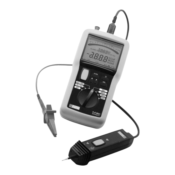
Afficheur à cristaux liquides rétro-éclairé Trappe à pile + béquille (non représentées sur le dessin) 2.1.2 1035 2 Bornes de sécurité Ø 4 mm (repérées " + " et " G "), une prise 3 points pour le cordon gardé ou la sonde déportée (repérée "... -
Page 7: Bargraph
> 25 V Tension > 25 V présente aux bornes de l'appareil D D D D D REL Différence entre mesure réelle et mesure en mémoire (ne fonctionne pas en tension sur les positions MΩ ) Buzzer actif Fonctionnement permanent (pas d'arrêt automatique) Piles déchargées 2.2.2 Bargraph Isolement >... -
Page 8: Touche
0, 1, 2, 3, 4, 5, 6, 7, 8, 9. 2.3.5 Touche 1039 et 1035 Un appui sur cette touche provoque l’allumage du rétro-éclairage de l’afficheur. Celui-ci s’éteindra automatiquement une minute plus tard. -
Page 9: Mesure D'isolement
L’appareil signale si la valeur mesurée sort de sa plage de mesure. Si la résistance d’isolement est supérieure à 400 MΩ (1039), 2 ou 20 GΩ (1035), le symbole OL s’affiche sur l’afficheur numérique de mesure. Dès que la mesure est supérieure à... -
Page 10: Capacité (1039)
Capacité (1039) La mesure de capacité correspond à la position 4000 nF du commutateur. La mesure est exprimée sur l'afficheur numérique accompagnée du symbole nF. La longueur de la ligne téléphonique mesurée est exprimée en km sur l'afficheur numérique des seuils, en fonction de la capacité... -
Page 11: Arrêt Automatique
Le bargraph indique l’autonomie de la pile, et l’affichage numérique de mesure indique l'autonomie disponible (de 0.00 à 1.00 = 0 à 100%). A tout moment, l’arrêt peut être obtenu en ramenant le commutateur en position OFF. Arrêt automatique Au bout de 5 minutes de fonctionnement sans manifestation de la présence de l’utilisateur (appui sur une touche du clavier, ou sur la touche jaune de la sonde de commande déportée, ou manœuvre du commutateur rotatif), l’appareil s’éteint... -
Page 12: Seuils D'alarme
> 0.100 MΩ pour la position MΩ - 100 V < 10.00 kΩ pour la position 40 kΩ sur le 1035 > 0.05 MΩ pour la position MΩ - 50 V > 0.10 MΩ pour la position MΩ - 100 V >... -
Page 13: Activation/Désactivation Des Seuils D'alarme
Par exemple, un seuil en isolement, à 2 GΩ sera mis en mémoire sous 399.9 MΩ sur le 1039, ou en mesure de résistance 700 kΩ deviendra 399.9 kΩ sur le 1035. Si le seuil a été "mal" programmé, il est corrigé lors de la mise en mémoire. -
Page 14: Utilisation
Pendant la programmation, si l’on tourne le commutateur sur une autre position, on perd ce que l’on vient de faire. Un deuxième appui long sur la touche permet de sortir du mode de programmation et d’enregistrer la valeur. 5. UTILISATION Pour visualiser la version logicielle et le numéro de série de l'appareil, appuyer sur la touche jaune lors de la mise en route de l'appareil par rotation du commutateur. -
Page 15: Mesure De Résistance
Mesure de résistance Mettre l’appareil en marche en positionnant le commutateur sur la position 40 kΩ (1039) ou 400 kΩ (1035). Raccorder les cordons des bornes + et - aux points de mesure. Relever la valeur de la résistance affichée (voir § 3.2). -
Page 16: Caracteristiques
Domaine de mesure : 1039 : sous 50 10 kΩ à 400 MΩ sous 100 V 20 kΩ à 400 MΩ 1035 : sous 50 V 10 kΩ à 2 GΩ sous 100 V 20 kΩ à 2 GΩ sous 250 V 50 kΩ... -
Page 17: Résistance
à travers l'appareil en 3 à 6 s/µF selon le calibre pour le 1039 et en moins de 2 s/µF pour le 1035. 6.2.3 Résistance Domaine de mesure : 0 à 40 kΩ pour le 1039 0 à... -
Page 18: Tension Ac (1039)
Domaine de mesure : 1039 : sous 50 10 kΩ à 400 MΩ sous 100 V 20 kΩ à 400 MΩ 1035 : sous 50 V 10 kΩ à 2 GΩ sous 100 V 20 kΩ à 2 GΩ sous 250 V 50 kΩ... -
Page 19: Alimentation
6.6. Conditions limites L’appareil est protégé sur tous les calibres contre une tension de 600 V AC/DC pour le 1039, 720 V AC/DC pour le 1035 appliquée en permanence, entre deux bornes quelconques. Le 1039 est protégé pendant 10 s contre une surtension accidentelle de 720 V sur tous les calibres. -
Page 20: Maintenance
6.8.1. Compatibilité Electromagnétique : Conformité CE Emission : NF EN 55 081 -1 (juin 92) Immunité : NF EN 55 082 -1 (janvier 98) 6.8.2. Protections mécaniques IP54 selon la NF EN 60529 (oct. 92) IK04 selon la NF EN 50102 (juin 95) 7. -
Page 21: Nettoyage
Pour toute intervention sous garantie ou hors garantie, retournez l’appareil à votre distributeur. 8. GARANTIE Notre garantie s’exerce, pour les 1039 et 1035, pendant 3 ans après la date de mise à disposition (Conditions Générales de Vente communiquées sur demande). -
Page 22: Pour Commander
1 pince crocodile rouge, 1 pointe de touche noire, 2 grip-fils (rouge et noir), 6 piles LR6 et cette notice de fonctionnement 5 langues. 1035 ................2116.90 Livré avec une sacoche de transport et d'utilisation "mains libres" pour l'appareil et ses accessoires, 2 cordons de sécurité... - Page 23 The voltage of the parts marked with this symbol may be dangerous. For safety reasons, this symbol will light up on the LCD screen as soon as a voltage is generated. Thank you for purchasing a 1039 or 1035 insulation tester. To get the best service from this instrument : read this user’s manual carefully...
- Page 24 The Megohmmeter .......... 26 1.1.2 Accessories ............. 26 DESCRIPTION ........... 27 Housing ................. 27 2.1.1 1039 ..............27 2.1.2 1035 ..............27 Display ................27 2.2.1 Symbols ............27 2.2.2 Bargraph ............28 2.2.3 Digital display ........... 28 Control keyboard ............28 2.3.1...
- Page 25 TO ORDER ............43 10. ATTACHMENT ..........107 10.1 Front views ..............107 10.1.1. 1039 ............. 107 10.1.2. 1035 ............. 108 10.2. Examples of applications .......... 109 10.2.1. Insulation measurements on electrical installations ......109 10.2.2. Measurement on electrical or telecom cable ..110 10.2.3.
-
Page 26: Presentation
1. PRESENTATION General Presentation 1.1.1 The Megohmmeter These portable instruments function with batteries or a vehicle battery. They can be used to check insulation and voltages and to measure resistances. The 1039 can also be used for: measurement of the capacitance of a telephone line current measurement measurement of the pure alternating component of a DC voltage. -
Page 27: Description
Backlit liquid crystal display Battery compartment + stand (not shown in the drawing) 2.1.2 1035 2 x 4 mm Ø safety terminals (labelled “ + ” and “ G “), a 3- point jack for the guarded lead or the remote control probe (labelled “... -
Page 28: Bargraph
Buzzer active Constant operation (no automatic shutdown) Batteries flat 2.2.2 Bargraph Insulation > 1.1 GΩ Insulation < 70 kΩ 2.2.3 Digital display Batteries low – must be changed Range exceeded - - - Insulation < 10 kΩ at 50 V, < 20 kΩ at 100 V, <... -
Page 29: Key
0, 1, 2, 3, 4, 5, 6, 7, 8 or 9. 2.3.5 1039 and 1035 When this key is pressed, the backlighting of the display comes on. It will be turned off automatically one minute later. When it is lit, you can turn the backlighting off by pressing this key again. -
Page 30: Insulation Measurement
The instrument indicates if the value measured is outside its measurement range. If the insulation resistance is greater than 400 MΩ (1039), 2 or 20 GΩ (1035), the OL symbol is displayed on the digital measurement display. When the measurement is greater than 1.1 GΩ (even on the 1039), symbol lights up on the right-hand side of the bargraph. -
Page 31: Capacitance (1039)
Capacitance (1039) Capacitance measurement corresponds to the 4000 nF position of the switch. The measurement is shown on the display accompanied by the nF symbol. The length of the telephone line measured is indicated in km on the digital threshold display, according to the programmed capacitance per unit length. -
Page 32: Automatic Shutdown
Automatic shutdown After 5 minutes without any activity by the user on the instrument (key press on the keyboard or on the yellow key on the remote control probe or turn of the rotary switch), the instrument shuts down automatically. It is then on standby. When this is the case, to start up the instrument again, all you have to do is press one of the keys, turn the switch or press the yellow key on the remote control probe. -
Page 33: Deactivation Of The Buzzer
For example, a 2 GΩ insulation threshold will be stored in the memory as 399.9 MΩ on the 1039, while for resistance measurement 700 kΩ will become 399.9 kΩ on the 1035. -
Page 34: Activation/Deactivation Of The Alarm Thresholds
If the threshold has been “wrongly” programmed, it is corrected when it is stored in the memory: For example, 002 MΩ will become 2.00 MΩ . 4.5.2 Activation/deactivation of the alarm thresholds The threshold corresponding to the switch position can be activated by a short press on the ALARM key. -
Page 35: Use
During programming, if you change the switch position, you lose what you have just done. You can quit the programming mode and record the value by another long press on the key. 5. USE To display the device software version and series number press the yellow button whilst switching on via the rotating switch. -
Page 36: Resistance Measurement
Resistance measurement Start up the instrument by setting the switch to 40 kΩ (1039) or 400 kΩ (1035). Connect the + and - leads to the measurement points. Note the resistance value displayed (see § 3.2). Note: The user can control the backlighting as required by pressing the key. -
Page 37: Specifications
Resolution 0.1 V Accuracy ± 3% R ±2 ct ± 3% R ±1 ct Input impedance 4 MΩ (1039) - 300 kΩ (1035) 6.2.2 Insulation Measurement range: 1039: at 50 V 0 kΩ to 400 MΩ at 100 V 0 kΩ to 400 MΩ... -
Page 38: Resistance
3 to 6 s/µF according to the measurement for the 1039 and in less than 2 s/µF for the 1035. 6.2.3 Resistance Measurement range : 0 to 40 kΩ for the 1039 0 to 400 kΩ... -
Page 39: Ac Voltage (1039)
Internal impedance: 4 MΩ Power supply The instruments are powered by 6 x 1.5 V alkaline batteries, type LR6. Average Average Measurement consumption* charge life Voltmeter (1039/1035) 57,600 25 mA Ammeter (1039) 5-seconds measurements Resistance (1039/1035) 50 mA 28,000 5-seconds measurements... -
Page 40: Variations In Nominal Field Of Use
The instrument is protected across all ranges against a constantly applied voltage, between any two terminals, of 600 V AC/DC on the 1039, and 720 V AC/DC on the 1035. The 1039 is protected for 10 s against an accidental overvoltage of 720 V across all the ranges. -
Page 41: Electromagnetic Compatibility: Ec Compliance
6.8.1. Electromagnetic compatibility: EC compliance Emission: NF EN 55 081 -1 (Ed. 92) Immunity: NF EN 55 082 -1 (Ed. 95) 6.8.2. Mechanical protection IP54 as per NF EN 60529 (Oct. 92) IK04 as per NF EN 50102 (June 95) 7. -
Page 42: Cleaning
Repairs under or out of guarantee: please return the product to your distributor 8. WARRANTY Our guarantee is applicable for 3 years (for 1039 and 1035) after the date on which the equipment is made available (extract from our General Conditions of Sale, available on request). -
Page 43: To Order
1 red crocodile clip, 1 black touch prod, 2 wire grips (red and black), 6 LR6 batteries and this 5-language user’s manual. 1035 ................2116.90 Delivered with a shoulder bag for transport and hands-free use of the instrument and its accessories, 2 elbowed-straight safety leads (red +black), 1.5 m long... - Page 44 Symbol auf dem LCD-Bildschirm angezeigt, wenn eine Spannung erzeugt wird. Wir bedanken uns bei Ihnen für den Kauf des Isolationsprüfers 1039 oder 1035 und das damit entgegengebrachte Vertrauen. Um die besten Ergebnisse mit Ihrem Meßgerät zu erzielen, bitten wir Sie :...
- Page 45 Das Megohmmeter .......... 47 1.1.2 Zubehör ............47 BESCHREIBUNG ..........48 Gehäuse ............... 48 2.1.1 1039 ..............48 2.1.2 1035 ..............48 Anzeige ................. 48 2.2.1 Symbole ............48 2.2.2 Bargraph ............49 2.2.3 Bestellnummer ..........49 Steuertastatur ............... 49 2.3.1...
- Page 46 GARANTIE ............63 BESTELLANGABEN ......... 64 10. ANHANG 10.1 Vorderseite ..............107 10.1.1. 1039 ............. 107 10.1.2. 1035 ............. 108 10.2. Anwendungsbeispiele ..........109 10.2.1. Isolationsmessungen bei Elektroinstallationen ....... 109 10.2.2. Messungen an elektrischen Kabeln oder Telefonleitungen (Leiter a und b) ....110 10.2.3.
-
Page 47: Vorstellung
1. VORSTELLUNG Allgemeine Vorstellung 1.1.1 Das Megohmmeter Diese tragbaren Geräte arbeiten mit Batterien oder Akkus. Sie ermöglichen die Prüfung von Isolationen, Spannungen und die Messung von Widerständen. Das 1039 ist außerdem geeignet: für die Messung der Kapazität einer Telefonleitung für die Strommessung für die Messung des Wechselspannungsanteils einer Gleichspannung. -
Page 48: Beschreibung
ALARM, Hintergrundbeleuchtete Flüssigkristallanzeige Batteriefach + Standbügel (auf der Abbildung nicht gezeigt) 2.1.2 1035 2 Sicherheitsbuchsen Ø 4 mm (gekennzeichnet mit " + “ und " G "), eine 3-Punkt-Buchse für die GUARD-Sicherheitsleitung oder die Sonde zur Fernbedienung (gekennzeichnet mit " - ") Funktionsschalter mit 6 Positionen: OFF, MΩ... -
Page 49: Bargraph
Informationen siehe Bedienungsanleitung > 25 V Spannung > 25 V liegt an den Buchsen des Geräts an ∆REL Differenz zwischen durchgeführter Messung und gespeichertem Messwert (funktioniert in den MΩ Positionen nicht bei Spannungen) Summer aktiv Dauerbetrieb (keine automatische Abschaltung) Batterien entladen 2.2.2 Bargraph Isolation >... -
Page 50: Taste
Änderung des Wertes der blinkenden Ziffern von 0, 1, 2, 3, 4, 5, 6, 7, 8, 9. 2.3.5 Taste 1039 und 1035 Durch Drücken dieser Taste wird die Hintergrundbeleuchtung der Anzeige eingeschaltet. Sie erlischt automatisch eine Minute später. Während des Leuchtens führt ein zweites Drücken zum Ausschalten der Hintergrundbeleuchtung. -
Page 51: Isolationsmessung
Das Gerät gibt eine Meldung an, wenn der gemessene Wert Messbereich herausfällt. Liegt Isolationswiderstand über 400 MΩ (1039), 2 oder 20 GΩ (1035), wird das Symbol OL auf der Digitalanzeige für die Messung angezeigt. Sobald der Messwert 1,1 GΩ überschreitet (auch beim 1039), wird das Symbol ganz rechts im Bargraph angezeigt. -
Page 52: Kapazität (1039)
Kapazität (1039) Die Kapazitätsmessung entspricht der Position 4000 nF des Funktionsschalters. Der Messwert wird zusammen mit dem Symbol nF auf der Digitalanzeige für die Messung angezeigt. Die Länge der gemessenen Telefonleitung wird auf der Digitalanzeige der Grenzwer te in Abhängigkeit der programmierten längenbezogenen Kapazität in km angezeigt. -
Page 53: Automatische Abschaltung
der Batterie an und die Digitalanzeige für den Messwert gibt den prozentualen Wert der verfügbaren Betriebsdauer wieder (von 0.00 bis 1.00 = 0 bis 100%). Das Gerät kann jederzeit ausgeschaltet werden, indem der Funktionsschalter auf die Stellung OFF gedreht wird. Automatische Abschaltung Nach 5 Betriebsminuten schaltet sich das Gerät automatisch aus, wenn kein Benutzereingriff festgestellt wurde (Drücken einer Taste... -
Page 54: Summer
> 0.050 MΩ bei der Position MΩ -50 V > 0.100 MΩ bei der Position MΩ -100 V < 10.00 kΩ bei der Position 40 kΩ beim 1035 > 0.05 MΩ bei der Position MΩ -50 V > 0.10 MΩ bei der Position MΩ -100 V... -
Page 55: Aktivierung/Deaktivierung Der Alarmgrenzwerte
Bei der Durchgangsprüfung zum Beispiel wird ein Grenzwert von 2 GΩ beim 1039 als 399.9 MΩ abgespeichert, bei der Widerstandsmessung wird ein Wert von 700 kΩ beim 1035 zu 399.9 kΩ . Wurde die Grenze "falsch" programmiert, wird sie bei der Speicherung korrigiert. -
Page 56: Programmierung Der Längenbezogenen Kapazität (1039)
Durch erneutes Drücken wird der gespeicherte Wert gelöscht und das Gerät kehrt in den normalen Modus zurück. Diese Taste kann zu jedem Zeitpunkt benutzt werden, außer für Spannungen in den Positionen MΩ . Programmierung der längenbezogenen Kapazität (1039) Befindet sich der Funktionsschalter in der Stellung nF, wird durch langes Drücken der Taste der Programmiermodus für die längenbezogene Kapazität der zu messenden Leitung... -
Page 57: Widerstandsmessung
Widerstandsmessung Setzen Sie das Gerät in Betrieb, indem Sie den Funktionsschalter auf die Position 40 kΩ (1039) oder 400 kΩ (1035) stellen. Verbinden Sie die Leitungen der Klemmen + und – mit den Messpunkten. Lesen Sie den angezeigten Widerstandswert ab (siehe § 3.2). -
Page 58: Ac Spannungsmessung (1039)
Auflösung 0,1 V Genauigkeit ± 3% Anz. ± 2 Digits ± 3% Anz. ± 1 Digit Eingangsimpedanz 4 MΩ (1039) - 300 kΩ (1035) 6.2.2 Isolation Messbereich: 1039: bei 50 V 10 kΩ bis 400 MΩ bei 100 V 20 kΩ bis 400 MΩ... -
Page 59: Widerstand
Die Restspannung an den Klemmen nach Loslassen der gelben Taste wird über die Messleitungen und das Gerät mit einer Geschwindigkeit von 3 oder 6 s/µF je nach Messung beim 1039 und mindestens 2 s/µF beim 1035. 6.2.3 Widerstand Messbereich : 0 bis 40 kΩ beim 1039 0 bis 400 kΩ... -
Page 60: Kapazität (1039)
Eigenimpedanz: 4 MΩ Stromversorgung Die Stromversorgung der Geräte erfolgt über 6 Stück 1,5V-Alkali- Batterien des Typs LR6. Verbrauch Betriebsdauer Messung Mittelwert* Mittelwert Voltmeter (1039/1035) Amperemeter 25mA 5 7.600 Messungen von 5 s (1039) Widerstandsmessung 50mA (1039/ 28.000 Messungen von 5 s Kapazitätsmesser... -
Page 61: Klimatische Bedingungen
Das Gerät ist in allen Messbereichen gegen eine Spannung von 600 V AC / DC beim 1039, 720 V AC/DC beim 1035 geschützt, die dauerhaft zwischen zwei beliebigen Klemmen anliegen kann. Das 1039 ist für 10 s gegen eine unbeabsichtigte Überspannung von 720 V in allen Messbereichen geschützt. -
Page 62: Einhaltung Internationaler Normen
Standbügel: Ermöglicht eine Neigung des Geräts um 30°. Wird bei Nichtbenutzung an die Rückseite des Gehäuses geklappt. 6.8. Einhaltung internationaler Normen Elektrische Sicherheit gemäß: IEC 1010-1 + A2 (Nov. 95), IEC 61557 (Feb. 97) und DIN EN 61557. Schutzisolierung: Verschmutzungsgrad: 2 Überspannungskategorie: III Zugelassene Spannung: 600 V 6.8.1. -
Page 63: Austausch Der Sicherung (1039)
Reparaturen während oder auáerhalb des Garantiezeitraumes : senden Sie die Geräte zu Ihrem Wiederverkäufer. 8. GARANTIE Unsere Garantie erstreckt sich auf eine Dauer (1039 und 1035) von drei Jahren ab dem Zeitpunkt der Bereitstellung des Geräts (Auszug aus unseren allg. Verkaufsbedingungen. Erhältlich auf Anfrage). -
Page 64: Bestellangaben
1 rote Krokodilklemme, 1 schwarze Prüfspitze, 2 Abgreifer (rot und schwarz), 6 Batterien LR6 und einer Bedienungsanleitung in 5 Sprachen. 1035 ................2116.90 Geliefert mit einer Tasche für Gerät und Zubehör für Transport und Freihandbetrieb, 2 Sicherheitsleitungen abgewinkelt-gerade (rot + blau) 1,5 m,... - Page 65 Per motivi di sicurezza, il simbolo si accenderà sul display LCD non appena viene generata una tensione. Avete acquistato uno tester d’isolamento 1039 o 1035 e vi ringraziamo della vostra fiducia. Per ottenere le migliori prestazioni dal vostro strumento : leggete attentamente queste istruzioni rispettate le precauzioni d’uso citate...
- Page 66 Il megaohmmetro ..........68 1.1.2 Gli accessori ............ 68 DESCRIZIONE ........... 69 Contenitore ..............69 2.1. 1039 ..............69 2.1.2 1035 ..............69 Display ................69 2.2.1 Simboli ............. 69 2.2.2 Bargraph ............70 2.2.3 Display digitale ..........70 Tastiera di comando ............. 70 2.3.1...
- Page 67 GARANZIA ............84 PER ORDINARE ..........85 10. ALLEGATO 10.1 Frontali ............... 107 10.1.1. 1039 ............. 107 10.1.2. 1035 ............. 108 10.2. Esempi applicativi ............109 10.2.1. Insulation measurements on electrical installations ......109 Misure d’isolamento sull’impianto ....109 10.2.2. Misure su cavo elettrico o telecom (fili a e b) 110 10.2.3.
-
Page 68: Presentazione
1. PRESENTAZIONE Presentazione generale 1.1.1 Il megaohmmetro Questi apparecchi portatili funzionano con pile o con batteria. Essi consentono di controllare gli isolamenti, le tensioni, e di misurare le resistenze. Il 1039 effettua anche: la misura di capacità di una linea telefonica la misura di corrente la misura della componente alternata di una tensione continua. -
Page 69: Descrizione
Display a cristalli liquidi retroilluminato Sportellino della pila + puntello (non raffigurati sul disegno) 2.1.2 1035 2 boccole di sicurezza Ø 4 mm (contrassegnate " + " et " G "), una presa a 3 punti per il cavo protetto o la sonda deportata (munita di contrassegno "... -
Page 70: Bargraph
∆REL Differenza fra la misura reale e la misura in memoria (non funziona in tensione sulle posizioni MΩ ) Cicalino attivo Funzionamento permanente (assenza di arresto automatico) Pile scariche 2.2.2 Bargraph Isolamento > 1,1 GΩ Isolamento < 70 kΩ 2.2.3 Display digitale Pile esaurite Superamento della portata - - -... -
Page 71: Tasto
0, 1, 2, 3, 4, 5, 6, 7, 8, 9. 2.3.5 Tasto 1039 e 1035: Premendo questo tasto si provoca l’accensione della retroilluminazione del display. Il display si spegnerà automaticamente dopo un minuto. Durante l’accensione, premere una seconda volta per spegnere la retroilluminazione. -
Page 72: Misura D'isolamento
L’apparecchio segnala se il valore misurato fuoriesce dalla fascia di misura. Se la resistenza d’isolamento è superiore a 400 MΩ (1039), 2 o 20 GΩ (1035), appare il simbolo OL sul display digitale di misura. Appena la misura è superiore a 1,1 GΩ... -
Page 73: Capacità (1039)
Capacità (1039) La misura di capacità corrisponde alla posizione 4000 nF del commutatore. La misura è espressa sul display digitale accompagnato dal simbolo nF. La lunghezza della linea telefonica misurata è espressa in km sul display digitale, in funzione della capacità lineica programmata. -
Page 74: Arresto Automatico
In qualsiasi momento l’arresto può essere ottenuto riportando il commutatore in posizione OFF. Arresto automatico Dopo 5 minuti di funzionamento senza manifestazione della presenza dell’utente (premendo un tasto della tastiera o il tasto giallo della sonda di comando deportata, o manovra del commutatore rotativo), l’apparecchio... -
Page 75: Disattivazione Del Cicalino
> 50 MΩ per la posizione MΩ -50 V > 100 MΩ per la posizione MΩ -100 V < 10,00 kΩ per la posizione 40 kΩ sul 1035 > 0,05 MΩ per la posizione MΩ -50 V > 0,10 MΩ per la posizione MΩ -100 V >... -
Page 76: Attivazione/Disattivazione Delle Soglie Di Allarme
Ad esempio, una soglia d’isolamento a 2 GΩ sarà memorizzata con 399.9 MΩ sul 1039, o in misura di resistenza 700 kΩ diventerà 399.9 kΩ sul 1035. Se la soglia è stata mal programmata, questa viene corretta al momento della memorizzazione. Ad esempio, 002 MΩ... -
Page 77: Programmazione Della Capacità Lineica (1039)
Programmazione della capacità lineica (1039) Quando il commutatore è posizionato su nF, premendo a lungo il tasto si entra in modalità di programmazione della capacità lineica della linea da misurare. Il valore memorizzato appare sul display digitale delle soglie assieme al simbolo nF/km. Se non ci sono valori programmati, il display indica per difetto 50 nF/km. -
Page 78: Misura Di Resistenza
(vedi § 4.5). Misura di resistenza Attivare l’apparecchio posizionando il commutatore su 40 kΩ (1039) o 400 kΩ (1035). Collegare i cavi delle boccole + e – ai punti di misura. Rilevare il valore della resistenza visualizzato.(vedi § 3.2). Nota: L’utilizzatore può comandare a piacere la retroilluminazione del display premendo il tasto Una soglia d’allarme può... -
Page 79: Caratteristiche
Risoluzione 0,1 V Precisione ± 3% L ±2 pti ± 3% L ±1 pto Impedenza d’ingresso 4 MΩ (1039) - 300 kΩ (1035) 6.2.2 Isolamento Campo di misura: 1039: con 50 V 10 kΩ a 400 MΩ con 100 V 20 kΩ... -
Page 80: Resistenza
3 a 6 s/µF per il 1039 e in meno di 2 s/µF per il 1035. 6.2.3 Resistenza Campo di misura: 0 a 40 kΩ per il 1039 0 a 400 kΩ per il 1035 Modelli 1039 e 1035: 1035 Portate 0.0..399.9... -
Page 81: Tensione Ac (1039)
Alimentazione L’alimentazione dell’apparecchio viene realizzata mediante 6 pile da 1,5 V alcaline di tipo LR6. Consumo Autonomia Misura medio* media Voltmetro (1039/1035) 25 mA 57.600 misure da 5 s Amperometro (1039) Resistenza (1039/1035) 50 mA 28.000 misure da 5 s... -
Page 82: Variazioni Nell'ambito Nominale Di Utilizzo
6.6. Condizioni limite L’apparecchio è protetto in tutti i calibri da una tensione di 600 V AC/DC, per il 1039, 720 V AC.DC per il 1035 applicata in permanenza fra due boccole qualsiasi. Il 1039 è protetto per 10 s da sovratensioni accidentali di 720 V in tutte le portate. -
Page 83: Compatibilità Elettromagnetica
6.8.1. Compatibilità elettromagnetica: Conformità CE Emissione: NF EN 55 081 -1 (ed. 92) Immunità: NF EN 55.082 -1 (ed. 95) 6.8.2. Protezioni meccaniche IP54 secondo la NF EN 60529 (ott. 92) IK04 secondo la NF EN 50102 (giugno 95) 7. MANUTENZIONE Per visualizzare la versione del software e il numero di serie dell’apparecchio, premere il tasto giallo all’avviamento dello stesso, ruotando il commutatore. -
Page 84: Pulizia
Per la riparazione in garanzia o fuorigaranzia : spedite il Vs. Strumento al Vs. Rivenditore. 8. GARANZIA La nostra garanzia si esercita (por 1039 o 1035), salvo disposizione specifica, per 3 anni dopo la data di messa a disposizione del materiale (estratto dalle nostre Condizioni... -
Page 85: Per Ordinare
1 pinza coccodrillo rossa, 1 puntale nero, 2 serrafili (rosso e nero), 6 pile LR6 e questo libretto d’istruzioni in 5 lingue. 1035 ................2116.90 Fornito con una borsa per il trasporto e per utilizzazione “a mani libere” per l’apparecchio e gli accessori. -
Page 86: Español
LCD tan pronto como se genera una tensión. Acaba de adquirir un controlador de aislamiento 1039 o 1035 y les agradecemos su confianza. Para obtener el mejor rendimiento de su aparato : lea atentamente estas instrucciones de servicio... - Page 87 El megaohmetro ..........89 1.1.2 Sus accesorios ..........89 DESCRIPCION ..........90 Carcasa ................ 90 2.1.1 1039 ..............90 2.1.2 1035 ..............90 Display ................90 2.2.1 Símbolos ............90 2.2.2 Barágrafo ............91 2.2.3 Visualización numérica ........91 Teclado de mando ............91 2.3.1...
- Page 88 PARA PEDIDO ..........106 10. ANEXO ............107 10.1 Frontal ................ 107 10.1.1. 1039 ............. 107 10.1.2. 1035 ............. 108 10.2. Ejemplos de aplicaciones .......... 109 10.2.1. Medidas de aislamiento en instalación eléctrica ......... 109 10.2.2. Medidas en cable eléctrico 10.2.3.
-
Page 89: Presentacion
1. PRESENTACION Presentación general 1.1.1 El megaohmetro Estos aparatos portátiles funcionan con pilas o con batería. Permiten controlar los aislamientos, las tensiones y medir las resistencias. El 1039 también realiza: la medida de capacidad de una línea telefónica la medida de corriente la medida de la componente alterna pura de una tensión continua. -
Page 90: Descripcion
Display de cristales líquidos retroiluminados Trampilla para pila + soporte (no representados en el dibujo) 2.1.2 1035 2 Bornes de seguridad Ø 4 mm (identificados " + " y " G "), una toma 3 puntos para el cordón conservado o la sonda distante (identificada "... -
Page 91: Barágrafo
> 25 V Tensión > 25 V presente en los terminales del aparato ∆REL Diferencia entre medida real y medida en memoria (no funciona en tensión en las posiciones MΩ ) Zumbador activo Funcionamiento permanente (no hay parada automática) Pilas descargadas 2.2.2 Barágrafo Aislamiento >... -
Page 92: Tecla
0, 1, 2, 3, 4, 5, 6, 7, 8, 9. 2.3.5 Tecla 1039 y 1035 Una pulsación sobre esta tecla provoca el encendido de la retroiluminación del display. El mismo se apagará... -
Page 93: Medida De Aislamiento
El aparato señala si el valor medido rebasa el rango de medida. Si la resistencia de aislamiento es superior a 400 MΩ (1039), 2 ó 20 GΩ (1035), se visualiza el símbolo OL en el display digital de medida. Tan pronto la medida es superior a 1,1 GΩ... -
Page 94: Capacidad (1039)
Capacidad (1039) La medida de capacidad corresponde a la posición 4000 nF del conmutador. La medida se expresa en el display digital acompañada del símbolo nF. La longitud de la línea telefónica medida se expresa en km en el display digital de los umbrales, en función de la capacidad lineal programada. -
Page 95: Parada Automática
El barágrafo indica la autonomía de la pila y el display digital de medida indica la autonomía disponible (de 0.00 a 1.00 = de 0 a 100%). En todo momento, la parada se puede obtener llevando el conmutador a la posición OFF Parada automática Al cabo de 5 minutos de funcionamiento sin que se manifieste la presencia del usuario (pulsación en una tecla del teclado o... -
Page 96: Zumbador
> 0.100 MΩ para la posición MΩ - 100 V < 10.00 kΩ para la posición 40 kΩ en el 1035 > 0.05 MΩ para la posición MΩ - 50 V > 0.10 MΩ para la posición MΩ - 100 V >... -
Page 97: Activación/Desactivación De Los Umbrales De Alarma
Por ejemplo, un umbral en aislamiento, a 2 GΩ, se pondrá en memoria a 399.9 MΩ en el 1039 o en medida de resistencia 700 kΩ será 399.9 kΩ en el 1035. Si el umbral ha sido “mal” programado, se corrige al poner en memoria. -
Page 98: Programación De La Capacidad Lineal (1039)
Programación de la capacidad lineal (1039) Cuando el conmutador se posiciona en nF, una pulsación larga en la tecla permite entrar en el modo de programación de la capacidad lineal de la línea a medir. El valor en memoria se visualiza en el display digital de los umbrales, al igual que el símbolo nF/km. -
Page 99: Medida De Resistencia
§ 4.5). Medida de resistencia Poner el aparato en funcionamiento posicionando el conmutador en la posición 40 kΩ (1039) o 400 kΩ (1035). Conectar los cables de los terminales + y – a los puntos de medida. Leer el valor de la resistencia visualizado (ver § 3.2). -
Page 100: Caracteristicas
0,1 V Precisión ± 3% L ±2 pt ± 3% L ±1 pt Impedancia de entrada 4 MΩ (1039) - 300 kΩ (1035) 6.2.2 Aislamiento Rango de medida: 1039: a 50 V de 10 kΩ a 400 MΩ a 100 V de 20 kΩ a 400 MΩ... -
Page 101: Resistencia
3 a 6 s/µF para el 1039 y en menos de 2 s/µF para el 1035. 6.2.3 Resistencia Rango de medida : de 0 a 40 kΩ para el 1039 de 0 a 400 kΩ... -
Page 102: Tensión C.a. (1039)
La alimentación de los aparatos se lleva a cabo por 6 pilas 1,5 V alcalinas de tipo LR6. Consumo Autonomía Medida media* media Voltímetro (1039/1035) 25 mA 57 600 medidas de 5 s Amperímetro (1039) Resistencia (1039/1035) 50 mA 28 000 medidas de 5 s Capacímetro... -
Page 103: Variations En El Dominio Nominal De Utilización
6.6. Condiciones límites El aparato está protegido en todos los calibres contra una tensión de 600 V CA/CD para el 1039, 720 V CA/CD para el 1035 aplicada en permanencia, entre dos bornes cualesquiera. El 1039 está protegido durante 10 s contra una sobretensión accidental de 720 V en todos los calibres. -
Page 104: Compatibilidad Electromagnética
6.8.1. Compatibilidad electromagnética: Conformidad ESTE Emisión: NF EN 55 081 -1 (ed. 92) Inmunidad: NF EN 55 082 -1 (ed. 95) 6.8.2. Protecciones mecánicas IP54 según la NF EN 60529 (ed. 92) IK04 según la NF EN 50102 (ed. 95) 7. -
Page 105: Limpieza
Reparacion en garanta y fuera de garantía : envie sus aparatos a su distribuidor. 8. GARANTIA Nuestra garantía se aplica para 1039 y 1035, durante los 3 años siguientes a la puesta a disposición del material (extracto de nuestras Condiciones Generale de Venta,... -
Page 106: Para Pedido
1 pinza cocodrilo roja, 1 punta de prueba negra, 2 Sujeta (rojo y negro), 6 pilas LR6 y este manual de instrucciones en 5 idiomas. 1035 ................2116.90 Entregado con una funda de transporte y de uso “manos libres” para el aparato y sus accesorios, 2 cables acodados de seguridad (rojo + azul) de 1,5 m, 1 cordón de seguridad conservado, toma triple-banana (negra) -
Page 107: Annexe 10.1 Faces Avant
10. ANNEXE - ATTACHMENT - ANHANG ALLEGATO - ANEXO 10.1 Faces avant - Front views - Vorderseite Frontali - Frontal 10.1.1. 1039... - Page 108 10.1.2. 1035...
-
Page 109: Exemples D'applications
10.2. Exemples d'applications - Examples of applications Anwendungsbeispiele - Esempi applicativi Ejemplos de aplicaciones 10.2.1. Mesures d'isolement sur installation électrique Insulation measurements on electrical installations Isolationsmessungen bei Elektroinstallationen Misure d’isolamento sull’impianto Medidas de aislamiento en instalación eléctrica INSTALLATION INSTALLATION INSTALLATION INSTALLAZIONE INSTALACION Les mesures sont effectuées entre conducteurs ou entre tous... -
Page 110: Mesures Sur Câble Électrique Ou Télécom
10.2.2. Mesures sur câble électrique ou télécom (fils a et b) Measurement on electrical or telecom cable (wires a and b) Messungen an elektrischen Kabeln oder Telefonleitungen (Leiter a und b) Misure su cavo elettrico o telecom (fili a e b) Medidas en cable eléctrico o telecom (alambres a y b) Isolement entre fils ou entre chaque fils et la terre. -
Page 111: Mesure De Capacité Entre Fils (1039)
10.2.3. Mesure de capacité entre fils (1039) Capacitance measurement between wires (1039) Kapazitätsmessung zwischen Leitern (1039 ) Misura di capacità fra fili (1039) Medida de capacidad entre hilos (1039 ) (calcul automatique de la longueur du câble) (automatic calculation of the length of the cable) (automatische Berechnung der Kabellänge) (calcolo automatico della lunghezza del cavo) (cálculo automático de la longitud del cable) -
Page 112: Mesures D'isolement Sur Moteur
10.2.4. Mesures d'isolement sur moteur Insulation measurements on motors Isolationsmessungen bei Motoren Misure d’isolamento sul motore Medidas de aislamiento en motor Moteur Motor Motor Motore Motor Enroulements moteurs Motor coils Motorwicklungen Avvolgimenti motore Devanados motor... -
Page 113: Accessoires
10.3 Accessoires - Accessories - Zubehör Accessori - Accesorios 10.3.1. Sacoche - Shoulder bag - Tasche Borsa - Funda 10.3.2. Utilisation de la sacoche - Use of the shoulder bag Benutzung der Tasche - Utilizzazione della borsa Utilización de la funda... -
Page 114: Sonde De Commande Déportée
10.3.3. Sonde de commande déportée Remote control probe Sonde zur Fernbedienung Sonda di comando deportata Sonda de mando a distancia... - Page 115 06 - 2000 Code 906 129 564 - Ed 3 Deutschland : CA GmbH - Straßburger Str. 34 - 77694 Kehl / Rhein - Tel : (07851) 99 26-0 - Fax : (07851) 7 52 90 España : CA Iberica - C/Roger de Flor N° 293 - 08025 Barcelona - Tel : (93) 459 08 11 - Fax : (93) 459 14 43 Italia : AMRA MTI - via Sant' Ambrogio, 23/25 - 20050 Bareggia Di Macherio (MI) - Tel : (039) 245 75 45 - Fax : (039) 481 561 Österreich : CA Ges.m.b.H - Slamastrasse 29 / 3 - 1230 Wien - Tel : (1) 61 61 9 61 - Fax : (1) 61 61 9 61 61 Schweiz : CA AG - Einsiedlerstrasse 535 - 8810 Horgen - Tel : (01) 727 75 55 - Fax : (01) 727 75 56...
Need help?
Do you have a question about the 1035 and is the answer not in the manual?
Questions and answers