Webasto Thermo 90 ST WDT Installation Instructions Manual
Hide thumbs
Also See for Thermo 90 ST WDT:
- Service and repair manual (54 pages) ,
- Installation instructions manual (40 pages) ,
- Installation manual (40 pages)

Related Manuals for Webasto Thermo 90 ST WDT


Summary of Contents for Webasto Thermo 90 ST WDT
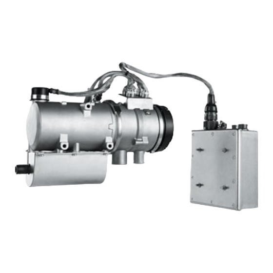
- Page 1 Wasserheizgerät Einbauanweisung Water heater Installation Instructions Thermo 90 ST WDT Thermo 90 ST WDT (Diesel)
- Page 2 Only genuine Webasto parts may be used. See also Webasto air and water heaters accessories catalogue. NEVER try to install or repair Webasto heating or cooling systems if you have not completed a Webasto training course, you do not have the necessary technical skills and you do not have the technical documentation, tools and equipment available to ensure that you can complete the installation and repair work properly.
-
Page 3: Table Of Contents
7.3. Integration in engine return line ........43 14.3. Fuel for Thermo 90 ST WDT........... 61 7.4. Fuel line ................ 44 14.4. Military standards met for Thermo 90 ST WDT....61 7.4.1. Line installation........... 44 7.4.2. Line design ..........45 7.4.3. - Page 4 Thermo 90 ST WDT Explanatory Notes on Document To provide you with a quick overview of the individual working steps, you will find an identification mark on the outside top corner of the page in question. Sections in italics contain an excerpt from the Directive ECE-R 122.
-
Page 5: Regulations Governing Installation
1.2. Additional documentation to be used These installation instructions do not contain all necessary information and instructions with regard to the installation of Thermo 90 ST WDT heaters. In addition, the operating instructions must also be used. -
Page 6: Use / Version
2.1.1. Parking heater Water heater for "diesel" fuel. The Thermo 90 ST WDT water heater was designed for use in military The heater is designed for 24 V. vehicles. When installing in other special vehicles, the applicable regulations must be taken into account. Other uses are possible in See chapter 14, "Technical data"... -
Page 7: Installation
Fig. 1 Permissible installation positions for Thermo 90 ST WDT (Requirement from ECE-R 122, Point 5.3.2.1.). The heater shall not constitute a risk of fire, even in the case of overheating. -
Page 8: Using Rub Guard
Technical Information Type label 3.4. Using rub guard A suitable rub guard must be provided when installing the heater wiring harness (see Fig. 1, marked with “X”) to prevent damage to the braided The label referred to in Annex 7, paragraph 4, or a duplicate, must be shield. -
Page 9: Installation Example
Coolant circuit Wiring harness Exhaust pipe Fig. 3 Example of Thermo 90 ST WDT installation in a vehicle. Without check valve (on left) and with check valve and thermostat (on right) Heat exchanger of vehicle heater T-piece 13) Control valve... -
Page 10: Integration In Coolant System
Any coolant running off should be collected using an appropriate container. The coolant hoses supplied by Webasto must always be used. If other hoses are used, they must at least comply with the standard DIN 73411, material class B. The hoses must be routed without kinking and preferably uphill from the heater to ensure perfect bleeding. -
Page 11: Fuel Integration
Fuel Fuel integration 7.1. General Information The fuel filler must not be situated in the passenger compartment and must be provided with an effective cap to prevent fuel spillage. (Requirement from ECE-R 122, Point 5.3.3.1.). In the case of liquid fuel heaters, where a supply separate from that of the vehicle is provided, the type of fuel and its filler point must be clearly labelled. - Page 12 Fuel Permissible fuel inflow height H1 At max. perm. pressure in fuel line [bar] 0.00 0.20 1.00 0.11 2.00 0.03 Permissible fuel suction height S1 At max. perm. vacuum in fuel line [bar] 0.00 -0.10 0.50 -0.06 1.00 -0.02 Suction side: D1: Inside diameter of fuel line = 2 mm.
-
Page 13: Integration In Vehicle Fuel Tank
Fuel 7.2. Integration in vehicle fuel tank The fuel must be removed from the fuel tank or a separate tank (see Fig. 5, Fig. 6 and Fig. 7). Sealing ring Also see chapter 5, "Installation example", with Fig. 3. Fuel standpipe The specified securing measures of the vehicle manufacturer must be complied with. -
Page 14: Integration In Engine Return Line
7.3. Integration in engine return line Fuel may only be removed from the return line with the special Webasto fuel standpipe. In this case, it must be ensured that the return line reaches almost up to the bottom of the fuel tank and is not closed by a check valve. -
Page 15: Fuel Line
Rub protection must be installed at sharp-edged transitions. To metering pump Do not route fuel lines through the vehicle interior. Fig. 8 Webasto fuel standpipe 7.4. Fuel line Since the lines normally cannot be routed with a constant rising gradient, the internal diameter must not be allowed to exceed a certain size. -
Page 16: Line Design
(see Fig. 4, Fig. 10 and Fig. 11). DIN 73378 may be used as fuel lines. The Thermo 90 ST WDT heater may only be operated with the DP2 or 30.2 metering pumps. -
Page 17: Fuel Filter
Fuel 7.4.7. Fuel filter Only a Webasto filter, order no. 487 171, is allowed to be used if the fuel is expected to be contaminated. Install vertically if possible, however at least horizontally. See Fig. 12. Note the installation position and direction of flow. -
Page 18: Label
If you change to low-temperature fuel, the heater must be operated in the boost mode (full load) for approx. 15 minutes so that fuel line and fuel pump are also filled with the new fuel. Also see the section 14.3, "Fuel for Thermo 90 ST WDT". -
Page 19: Combustion Air Supply
Combustion air Combustion air supply The air inlet must be so positioned or guarded that blocking by rubbish or A ventilation opening measuring at least 6 cm is required if the heater is luggage is unlikely. installed in an enclosed box. The size of the ventilation opening must be (Requirement from ECE-R 122, Point 5.3.5.2.). -
Page 20: Exhaust System
9.2. Exhaust silencer onto temperature-sensitive vehicle parts. It is not permissible to operate the Thermo 90 ST WDT heater without exhaust silencer. The exhaust outlet must be located so as to prevent emissions from The exhaust silencer must be installed near the heater and must not be entering the vehicle through ventilators, heated air inlets or opening installed near the intake opening for the combustion air. - Page 21 Exhaust gas Fig. 14 Exhaust outlet (installation position)
-
Page 22: Electrical Connections
(Requirement from ECE-R 122, Appendix 7, Point 7.1.). The heater can be switched on and off using the following Webasto cont- rols: – The standard timer is connected as shown in the circuit diagram Fig. 16. -
Page 23: Earth Connection
The use of an adapter wiring harness between the heater and the control unit can affect the EMC suitability of the device and must be clarified with Webasto before use. 10.8. Setting control temperatures If the “Engine on”/”Engine off” signal (Terminal D+) is active on the control unit (12-pin vehicle connector, Pos. -
Page 24: Circuit Diagrams
Electrical system Circuit diagrams The circuit diagrams show the possible circuits: – Circuit diagram for Thermo 90 ST WDT, parking heater with On/Off switch: Fig. 16 – Circuit diagram for Thermo 90 ST WDT, parking heater with standard timer: Fig. 17 For the legend for wiring diagrams, see Table 1, Table 2 and Table 3. - Page 25 Temperature at coolant outlet (see table in section 10.8.) Diagnostics Only possible via adapter wiring harness Earth connection Heater Thermo 90 ST WDT Control unit Thermo 90 ST WDT Flame monitor Temperature sensor Temperature limiter/overheating protection “Heating” symbol in the display...
- Page 26 Electrical system Table 3 Legend for wiring diagrams, Part 2 of 2 Item Description Comment Plug connector, 2-pin W bus PC diagnosis Plug connector, 2-pin on Pos. Y1 Plug connector, 12-pin on Pos. A2 Plug connector, 3-pin on Pos. A2 Plug connector, 12-pin on Pos.
- Page 27 Electrical system Control unit Heater Fig. 16 Circuit diagram for Thermo 90 ST WDT, parking heater with On/Off switch...
- Page 28 Electrical system Control unit Heater Fig. 17 Circuit diagram for Thermo 90 ST WDT, parking heater with standard timer...
-
Page 29: Initial Start-Up
It is recommended that the heater circulation pump be put into operation with the component test function of the Webasto Thermo Test PC Diagno- sis to support bleeding. Before the heater is operated for the first time, the coolant temperature should be <... -
Page 30: Malfunctions
Mechanical system Malfunctions To eliminate a fault which has resulted in a fault lock-out, proceed 13.2.1. Equipment with standard timer according to the workshop manual. When equipped with the standard timer, a fault output appears in the dis- play of the standard timer: F 00/-- Heater lock-out or control unit defect, 13.1. -
Page 31: Equipment With Switch
Overheating *: F 12 and F 13 are faults without a fault output in the display. Circulation pump interrupt or Only visible with Webasto Thermo Test PC-Diagnosis. circulation pump short-circuit F 12 * Battery isolation switch short-circuit 13.2.2. -
Page 32: Technical Data
Besides this fuel, the heater has been tested successfully with the fuels according to the NATO designation F-34, F-35, F-44 and F-63. 14.4. Military standards met for Thermo 90 ST WDT The Thermo 90 ST WDT heater meets the following military standards: – MIL-STD-810F – MIL-STD-461F... - Page 33 Heater Operation Thermo 90 ST WDT Approval symbol 122R-00 0217 03 4881 Model Water heater with Ferro-tec technology Heat output Max. 9.1 kW regulating range 1.8 to 7.6 kW Fuel Diesel according to DIN EN 590 and fuels according to NATO designation F-34, F-35, F-44 and F-63 Fuel consumption Max.
- Page 34 Technical Information 1) Combustion-air inlet 2) Exhaust outlet 3) Fuel inlet 4) Coolant inlet 5) Coolant outlet Fig. 18 Dimensions of the heater and control unit...
- Page 36 Die Telefonnummer des jeweiligen Landes entnehmen Sie bitte dem Webasto Servicestellenfaltblatt oder der Webseite Ihrer jeweiligen Webasto-Landesvertretung. In multilingual versions the German language is binding. The telephone number of each country can be found in the Webasto service center leaflet or the website of the respective Webasto representative of your country. Webasto Thermo & Comfort SE...
Need help?
Do you have a question about the Thermo 90 ST WDT and is the answer not in the manual?
Questions and answers