D-Link DMC-805G User Manual
1000base-t to mini-gbic media converter
Hide thumbs
Also See for DMC-805G:
- Quick installation manual (24 pages) ,
- Quick installation manual (13 pages)

Related Manuals for D-Link DMC-805G


Summary of Contents for D-Link DMC-805G
-
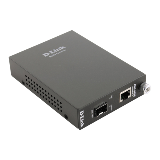
Page 1: Media Converter
DMC-805G 1000Base-T to mini-GBIC Media Converter User’s Guide RECYCLABLE 1907MC1002S6000 Rev.1.00... -
Page 2: Table Of Contents
TABLE ONTENTS INTRODUCTION ........... 1 ......... 1 BOUT EDIA ONVERTER PRODUCT FEATURES ......... 1 INSTALLATION ............ 2 ......2 ELECTING A ITE FOR THE QUIPMENT ............2 LIDING WITCH ..........3 NSTALLING IN A HASSIS ......4 ANAGEMENT THE EDIA ONVERTER ............ -
Page 3: Introduction
Introduction Thank you for choosing the 1000Base Gigabit Ethernet Media Converter, The Converter introduced here provides one channel media conversion between 1000BASE-T and 1000BASE-SX/LX through mini-GBIC module. About Media Converter Media Converter is a network technology specified by IEEE 802.3ab 1000BASE-T and IEEE 802.3z 1000BASE-SX/LX standards. -
Page 4: Installation
Installation This chapter gives step-by-step installation instructions for the DMC-805G. Selecting a Site for the Equipment As with any electric device, you should place the equipment where it will not be subjected to extreme temperatures, humidity, or electromagnetic interference. Specifically, the site you select should... -
Page 5: Installing In A Chassis
Switch 1 : On -> Forced Mode Off -> Auto Negotiation mode Switch 2 : On -> LLR enable Off -> LLR disable Installing in a Chassis The Converter can be fit into any of the expansion slots on a special designed chassis. -
Page 6: Management The Media Converter
Management the Media Converter There is a management module that can control this media converter through the chassis system, this media converter can be controlled through Web Browser, SNMP and terminal emulation program. The management module will detect the default reset on the DIP switches and display out the status, also the management module can control the function through the chassis system. -
Page 7: Link Pass Through Function
Link Pass Through Function LLCF (Link Loss Carry Forward) When a device connected to the converter and the TP line loss the link, the converter’s fiber will disconnect the link of transmit, so that the other ends will know that there is a linkage error on this end. And when the Fiber line loss the link, the converter’s TP will disconnected, and the other end will know that there is linkage problem exist. -
Page 8: Link Status
Me d ia Me d ia Co nve rte r A Co nve rte r B LINK 2 LINK 1 Fib e r Fib e r C o p p e r T X RX T X RX C o p p e r Ca b le 1 Ca b le 2 Ca b le 3... -
Page 9: Specifications
Specifications Standards: IEEE802.3ab 1000BASE-T IEEE802.3z 1000BASE-SX/LX Data Transfer Rate: 1488000pps for 1000Mbps Duplex Mode: Full Duplex Mode LED indicators: PWR, LNK/ACT Cable 1000BASE-T -- 4 pair Cat. 5, EIA/TIA-568 100-ohm screened twisted-pair (STP), up to 100m 1000BASE-SX -- 62.5/125μ m multi-mode fiber optic cable, up to 220m 50/125μ...
Need help?
Do you have a question about the DMC-805G and is the answer not in the manual?
Questions and answers