Kärcher NT 20/1 ME Classic Service Manual
Hide thumbs
Also See for NT 20/1 ME Classic:
- Original instructions manual (144 pages) ,
- Manual (32 pages) ,
- Operating instructions manual (20 pages)

Related Manuals for Kärcher NT 20/1 ME Classic


Summary of Contents for Kärcher NT 20/1 ME Classic
- Page 1 NT 20/1 ME Classic NT 30/1 ME Classic NT 38/1 ME Classic Service Manual English 5.906-580.0 Rev. 00 (07/13)
-
Page 2: Table Of Contents
Contents Contents........... . Preface . -
Page 3: Preface
Preface Technical Features Good service work requires extensive and practice- 4.1 General oriented training as well as well-structured training Wet / dry vacuum cleaner for cleaning floors and – materials. walls for commercial use. Hence we offer regular basic and advanced training Container capacity: 38 litres –... -
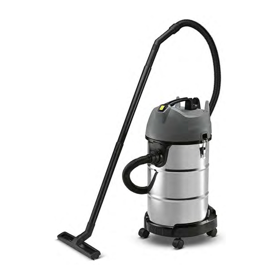
Page 4: Parts Of The System
Parts of the system 5.1 Overview 1 Container 20/30/38 litres 2 Suction air guide 3 Power switch 4 Carrying handle 5 Cable hook 6 Container closure 7 Accessory storage container 8 Steering roller English 5.906-580.0 Rev. 00 (07/13) -
Page 5: View From The Inside
5.2 View from the inside 1 Container closure 2 Fleece filter 3 Filter basket English 5.906-580.0 Rev. 00 (07/13) -
Page 6: Accessories
5.3 Accessories The following accessories are enclosed in the device: 1 Suction hose with manifold 2 Suction tube, two-parts, plastic 3 Floor nozzle English 5.906-580.0 Rev. 00 (07/13) -
Page 7: Basic Settings And Service Procedures
Basic settings and service procedures Danger First pull out the plug from the mains before carrying out any tasks on the machine. 6.1 Overview of the individual parts of the suction head 6.1.1 Cover English 5.906-580.0 Rev. 00 (07/13) -
Page 8: Turbine Casing And Suction Turbine
6.1.2 Turbine casing and suction turbine English 5.906-580.0 Rev. 00 (07/13) -
Page 9: Overview Of The Components Of The Container And The Chassis
6.2 Overview of the components of the container and the chassis English 5.906-580.0 Rev. 00 (07/13) -
Page 10: Remove The Appliance Cover
6.3 Remove the appliance cover Remove suction basket from the container. Unscrew the screws of the top part of the casing. Remove the top part of the casing. 6.4 Electrical components of the appliance 1 Ferrit ring (anti-interference ring) 2 Connection cable suction turbine 3 Power switch 4 Cover air duct suction turbine... -
Page 11: Replace Appliance Switch
6.5 Replace appliance switch Remove switch top. Lever the appliance switch out of the holder. Pull the connecting cable out on the appliance switch. 1 Connections suction turbine 2 Connections power cable 6.6 Replace de-interference capacitor Note The anti-interference capacitor is firmly connected with the connection cable of the suction turbine. -
Page 12: Replacing The Suction Turbine
6.7 Replacing the suction turbine Remove the appliance switch as described in the chapter "Replacing the appliance switch". Remove the inner cover from the base support of the suction basket. 1 Connecting cable, suction turbine (M1) 2 Sealing ring of upper motor bearing 3 Glide contacts (carbon brushes). -
Page 13: Float
6.7.2 Float The vacuum channel is equipped with a float. If the maximum admissible wastewater level in the container is reached, the float seals against the cone of the suction turbine and the intake flow is interrupt- ed in order to protect the suction turbine against moisture. -
Page 14: Installing The Suction Turbine
6.7.3 Installing the suction turbine Align the suction turbine in the turbine holder by means of the outer cone during installation. Loosely apply the inside cover. During application, ensure that the guides engage with each other. Route the cable through the opening and place it in the retainer. -
Page 15: Replacing The Mains Cable
6.8 Replacing the mains cable Unscrew the safety screws of the pull relief. Open pull relief so that the mains cable can be pulled out. Remove the ferrite core from the holder, for this purpose slightly twist the holder. ... -
Page 16: Maintenance Jobs On The Container
6.9 Maintenance jobs on the container 6.9.1 Replacing the Me container Note The container is engaged in the bumper (chassis). All snap-in noses must be released for disassembly. In the event that snap-in noses break off during disas- sembly, the bumper must also be replaced. ... -
Page 17: Replacing The Steering Roller
6.9.2 Replacing the steering roller Pull the steering roller out of the container and re- place it. 6.10 Replacing the container closure Drill out rivets. Replace and rivet the container closure. Note When installing the container closure, ensure that the container is not damaged during riveting. -
Page 18: Troubleshooting
Troubleshooting Danger First pull out the plug from the mains before carrying out any tasks on the machine. 7.1 Suction turbine does not run Turn on the appliance. Check cables, plugs and mains supply. Check/replace the appliance switch. ... -
Page 19: Technical Documentation
Technical Documentation Appliance type Appliance no.: Circuit dia- Operating in- Spare parts gram structions list NT 38/1 Me Classic *EU 1.428-530.0 0.089-441.0 5.964-393.0 5.971-469.0 NT 38/1 Me Classic *CN 1.428-532.0 0.089-441.0 5.964-393.0 5.971-469.0 NT 38/1 Me Classic *SEA 1.428-534.0 0.089-441.0 5.964-393.0 5.971-469.0 NT 38/1 Me Classic *AU... -
Page 20: Circuit Diagram
8.4 Circuit diagram The status of the attached circuit diagram represents please always use the current circuit diagram in DI- the creation date of the service manual. This circuit SIS. diagram is not updated. When working on the device, English 5.906-580.0 Rev. 00 (07/13)
Need help?
Do you have a question about the NT 20/1 ME Classic and is the answer not in the manual?
Questions and answers