Table of Contents
Advertisement
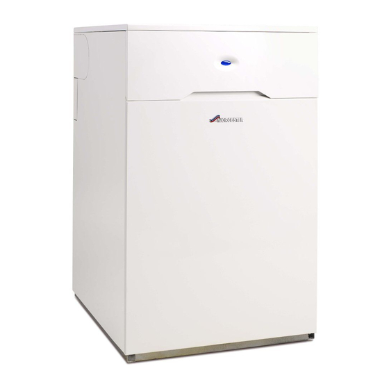
Installation, Commissioning and Servicing instruction manual
Floor Standing oil-fired Condensing Combination Boiler using Conventional and Room
Sealed Flue
ErP
Greenstar Heatslave II
12/18, 18/25 & 25/32
For fully pumped open vent or sealed central heating systems and domestic hot water cylinders.
These appliances are for use with Kerosene (Class C2) only.
UK
Advertisement
Table of Contents


Need help?
Do you have a question about the Greenstar Heatslave II ErP 12/18 and is the answer not in the manual?
Questions and answers