Table of Contents
Advertisement
Quick Links
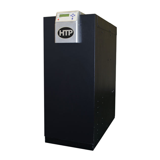
Elite Plus
Heating Boiler
INSTALLATION
START-UP
MAINTENANCE
PARTS
Models
ELP-110 / ELP-199
Heat Exchanger Bears the ASME "H" Stamp
This manual must only be used by a qualified heating installer/service technician. Read all instructions in this manual before installing.
Perform steps in the order given. Failure to comply could result in substantial property damage, severe personal injury, or death.
NOTICE: HTP reserves the right to make product changes or updates without notice and will not be held liable for typographical errors
in literature.
NOTE TO CONSUMER: PLEASE KEEP ALL INSTRUCTIONS FOR FUTURE REFERENCE.
120 Braley Rd. P.O. Box 429
East Freetown, MA 02717-0429
www.htproducts.com
LP-294 REV. 9.2.14
Advertisement
Table of Contents

Related Manuals for HTP ELP-110


Summary of Contents for HTP ELP-110
-
Page 1: Heating Boiler
Perform steps in the order given. Failure to comply could result in substantial property damage, severe personal injury, or death. NOTICE: HTP reserves the right to make product changes or updates without notice and will not be held liable for typographical errors in literature. - Page 2 IF THE INFORMATION IN THIS MANUAL IS NOT FOLLOWED EXACTLY, A FIRE OR EXPLOSION MAY RESULT, CAUSING PROPERTY DAMAGE, PERSONAL INJURY, OR LOSS OF LIFE. DO NOT STORE GASOLINE OR OTHER FLAMMABLE VAPORS AND LIQUIDS IN THE VICINITY OF THIS OR ANY OTHER APPLIANCE. WHAT TO DO IF YOU SMELL GAS •...
-
Page 3: For The Installer
In some circumstances, the property owner of his/her agent assumes the role, and at government installations, the commanding officer or departmental official may be the AHJ. NOTE: HTP, Inc. reserves the right to modify product technical specifications and components without prior notice. FOR THE INSTALLER This manual must only be used by a qualified heating installer/service technician. -
Page 4: Table Of Contents
COVERED BY WARRANTY. IMPORTANT In accordance with Section 325 (f) (3) of the Energy Policy and Conservation Act, HTP, Inc. has provided this boiler with multiple features designed to save energy by reducing the boiler water temperature as heating load decreases. - Page 5 B. LEVELING ....................................12 C. CLEARANCES FOR SERVICE ACCESS ..........................13 D. RESIDENTIAL GARAGE INSTALLATION ..........................14 E. EXHAUST VENT AND INTAKE PIPE ............................14 F. PREVENT COMBUSTION AIR CONTAMINATION ........................14 G. REMOVING A BOILER FROM A COMMON VENT SYSTEM ....................15 H.
- Page 6 B. GAS PIPING ..................................... 42 C. CHECK INLET GAS PRESSURE ............................. 43 PART 7 – FIELD WIRING ................................44 A. INSTALLATION MUST COMPLY WITH: ..........................44 B. FIELD WIRING TERMINATIONS .............................. 44 C. FIELD WIRING ..................................44 D. LINE VOLTAGE WIRING FOR STANDARD BOILER ......................45 E.
-
Page 7: Part 1 - General Safety Information
BOILER START-UP REPORT ..............................78 MAINTENANCE REPORT ................................. 78 MAINTENANCE NOTES .................................. 82 HTP CUSTOMER INSTALLATION RECORD FORM........................83 PART 1 – GENERAL SAFETY INFORMATION A. PRECAUTIONS This boiler is for indoor installations only. Clearance to combustible materials: 0” top, bottom, sides and back. Left side has all boiler mechanical connections. -
Page 8: Improper Combustion
Due to the low water content of the boiler, improper sizing of the boiler with regard to heating system load will result in excessive cycling and accelerated component failure. HTP DOES NOT warrant failures cause by improperly sized boiler applications. DO NOT oversize the boiler to the system. -
Page 9: Boiler Water Chemistry
These chemicals can attack gaskets and seals in water boilers, are poisonous if consumed, and can cause injury or death. Consider boiler piping and installation when determining boiler location. NOTE: Damages resulting from incorrect installation or from use of products not approved by HTP, Inc. ARE NOT covered by warranty. PART 2 – BEFORE YOU START A. -
Page 10: How Boiler Operates
• CSD-1 Form • H-3 Data Sheet B. HOW BOILER OPERATES ® Elite Plus condensing technology intelligently delivers highly efficient hydronic heating by adjusting for altitude and fuel (liquid propane or natural gas) without the need for conversion or physical adjustment. Outlined below are the features of the system and how they operate: Stainless Steel Heat Exchanger - The highly efficient stainless steel heat exchanger is designed to extract all available heat from the supply line before it is exhausted. -
Page 11: Optional Equipment
Test Mode – Allows installer to test combustion or operation of pumps when commissioning system and check pump operation during maintenance and service procedures. C. OPTIONAL EQUIPMENT Below is a list of optional equipment available from HTP. These additional options may be purchased through your HTP distributor: • Wall Mount Bracket (Part # 7450P-211) •... -
Page 12: Leveling
This boiler is certified for indoor installations only. Do not install the boiler outdoors. Failure to install this boiler indoors could result in substantial property damage, severe personal injury, or death. 2. Check for nearby connections to: • System water piping •... -
Page 13: Clearances For Service Access
Hot water pipes – at least 1” from combustible materials. • Exhaust vent pipe – at least 1” from combustible materials. Figure 3 – Specifications and Dimensions Drawing MODEL* SHIPPING WEIGHT ELP-110 27.3 11.8 ELP-199 27.3 11.8 Table 1 – Dimensions and Weights... -
Page 14: Residential Garage Installation
D. RESIDENTIAL GARAGE INSTALLATION If the boiler is located in a residential garage, per ANSI Z223.1: • Mount the bottom of the boiler a minimum of 18” above the floor of the garage, to ensure the burner and ignition devices are well off the floor. -
Page 15: Removing A Boiler From A Common Vent System
G. REMOVING A BOILER FROM A COMMON VENT SYSTEM Do not install the boiler into a common vent with any other appliance. This will cause flue gas spillage or appliance malfunction, resulting in possible substantial property damage, severe personal injury, or death. Failure to follow all instructions can result in flue gas spillage and carbon monoxide emissions, causing severe personal injury or death. -
Page 16: General Piping Information
Plumbing of this product should only be done by a qualified, licensed plumber in accordance with all local plumbing codes. The boiler is designed to be connected to an indirect water heater to supply domestic hot water. HTP offers indirect water heaters in a wide range of gallon sizes in either stainless steel or glass-lined construction. -
Page 17: Backflow Preventer
All piping methods shown in this manual use primary/secondary connection to the boiler loop. This is to avoid the possibility of inadequate flow through the boiler. For other piping methods, consult your local HTP representative or refer to the detailed piping drawings in this manual. -
Page 18: Piping Details
On a boiler installed above radiation level, some states and local codes require a low water cut off device, which is an optional part available through HTP (Part # 7450P-225). Check with local codes for additional requirements. If the boiler supplies hot water to heating coils in air handler units, flow control valves or other devices must be installed to prevent gravity circulation of boiler water in the coils during the cooling cycle. - Page 19 Figure 5 – Single Boiler with Zone Valves, DHW Priority, and Outdoor Reset – Primary/Secondary - NOTES: 1. This drawing is meant to show system piping concept only. Installer is responsible for all equipment and detailing required by local codes. 2.
- Page 20 Figure 6 – Single Boiler with Zone Valves and DHW Priority – Single Temperature – Standard Piping NOTES: 1. This drawing is meant to show system piping concept only. Installer is responsible for all equipment and detailing required by local codes. 2.
- Page 21 Figure 7 – Single Boiler with Pumps and DHW Priority, Outdoor Reset – Primary/Secondary NOTES: 1. This drawing is meant to show system piping concept only. Installer is responsible for all equipment and detailing required by local codes. 2. All closely spaced tees shall be within 4 pipe diameters center to center spacing. 3.
- Page 22 Figure 8 – Single Boiler with Pumps and DHW Priority – Single Temperature – Standard Piping NOTES: 1. This drawing is meant to show system piping concept only. Installer is responsible for all equipment and detailing required by local codes. 2.
- Page 23 Figure 9 – Multiple Boilers with Primary / Secondary Piping NOTES: 1. This drawing is meant to show system piping concept only. Installer is responsible for all equipment and detailing required by local codes. 2. All closely spaced tees shall be within 4 pipe diameters center to center spacing. 3.
-
Page 24: Piping Installation
MINIMUM BOILER WATER VOLUME MODEL MINIMUM FLOW (GPM) ELP-110 ELP-199 Table 5 – Minimum Heat Exchanger Water Volumes The heat exchanger has a pressure drop that must be considered in your system design. Refer to Table 6 for pressure drop through the heat exchanger. -
Page 25: Check/Control Water Chemistry
Tables 8 and 9 represent combined flow rates and pipe sizes when using multiple boilers to design the primary circuit manifold system. To size, simply add the number of boilers and the required flow rates for the system design temperature. Example: (5) ELP-199®... -
Page 26: Fill And Purge Heating System
Pressure relief valve: Factory supplied on boiler. The pressure relief valve is sized to ASME specifications. Storage tank may require additional relief valves depending on local codes. MINIMUM PIPE SIZES ELP-110 1” NPT or Copper ELP-199 1 ¼” NPT or Copper Table 10 K. -
Page 27: Glycol Antifreeze Solutions
Upon completion, make sure that the fill valve and zone valves are in automatic positions. You must also assure the purge and shut off valves are in open positions. L. GLYCOL ANTIFREEZE SOLUTIONS Use only inhibited propylene glycol solutions which are specially formulated for hydronic systems. Ethylene glycol is toxic and can attack gaskets and seals used in hydronic systems. -
Page 28: General
A. GENERAL This boiler is certified as a “Category IV” appliance, and requires a special venting system. The vent system will operate with a positive pressure in the pipe. Exhaust gases must be piped directly outdoors using the vent materials and rules outlined in these instructions. Do not connect vent connectors serving appliances vented by natural draft into any portion of mechanical draft systems operating under positive pressure. -
Page 29: Requirements For Installation In Canada
When installing AL29-4C vent piping, install a PVC-to-stainless adapter at the boiler vent connection, and at the termination when using an HTP PVC termination kit. DO NOT mix AL-29-4C piping from different manufacturers unless using adapters specifically designed for the purpose by the manufacturer. -
Page 30: Exhaust Vent And Intake Pipe Location
D. EXHAUST VENT AND INTAKE PIPE LOCATION Figure 11 – ANSI Z223.1 / NFPA 54 for US and CAN/CSA B149.1 for Canada – Exit Terminals for Direct-Vent Venting Systems DETERMINE EXHAUST VENT AND INTAKE PIPE LOCATION – FIGURE 11 NOTES: A. - Page 31 Condensate from the boiler is slightly acidic with a pH of 3.2 - 4.5. To avoid long term damage to the drainage system and to meet local code requirements, HTP recommends neutralizing the condensate with a Condensate Neutralizer Kit (Part # 7450P-212 for ELP- 110/199).
- Page 32 Figure 12 – Condensate Piping NOTES: 1. Condensate line must be pitched at least 1/4" per foot to properly drain. If this cannot be done, or a very long length of condensate hose is used, you must increase the condensate line to a minimum of 1” ID and place a tee in the line after the condensate neutralizer to properly reduce vacuum lock in the drain line.
-
Page 33: Exhaust Vent And Intake Pipe Sizing
The minimum total equivalent length is 16 feet. d. The size of venting on the ELP-110 can also be reduced in order to accommodate existing vent sizes. When reducing down to a 2” vent from a 3” vent, the total equivalent length shall not exceed 100 equivalent feet. Vent reduction must begin at the boiler. -
Page 34: Exhaust Vent And Intake Pipe Installation
14. A screened straight coupling is provided with the appliance for use as an outside exhaust termination. 15. A screened inlet air tee is provided with the appliance to be used as an outside intake termination. The following information on Table 15 lists optional exhaust/intake terminations available from HTP: DESCRIPTION STOCK CODE 3”... -
Page 35: Sidewall Venting W/ Tee (Intake) And Coupling (Exhaust)
H. SIDEWALL VENTING W/ TEE (INTAKE) AND COUPLING (EXHAUST) Figure 14 – Sidewall Venting with Tee (Intake) and Coupling (Exhaust) – LP-293-E NOTE: Vent piping should be 12” over anticipated maximum snow level. NOTE: Drawing is meant to demonstrate system venting ONLY. All vent pipes must be glued, properly supported, and the exhaust must be pitched a minimum of ¼”... -
Page 36: Vertical Venting W/ Tee (Intake) And Coupling (Exhaust)
I. VERTICAL VENTING W/ TEE (INTAKE) AND COUPLING (EXHAUST) Figure 15 – Vertical Venting - LP-293-F NOTE: Vent piping should be 12” over anticipated maximum snow level. NOTE: Drawing is meant to demonstrate system venting ONLY. All vent pipes must be glued, properly supported, and the exhaust must be pitched a minimum of ¼” per foot back to the boiler to allow drainage of condensate. -
Page 37: Horizontal Venting
J. HORIZONTAL VENTING Figure 16 – Horizontal Venting - NOTE: Drawing is meant to demonstrate system venting ONLY. NOTES: A. For every 1” of overhang, the exhaust vent must be located 1” vertical below overhang (overhang means top of building structure and not two adjacent walls [corner of building]). -
Page 38: Unbalanced Flue / Vertical Vent
K. UNBALANCED FLUE / VERTICAL VENT Figure 17 – LP-293-T – Unbalanced Flue/Vertical Vent - NOTE: Drawing is meant to demonstrate system venting ONLY. All vent pipes must be glued, properly supported, and the exhaust must be pitched a minimum of ¼” per foot back to the boiler to allow drainage of condensate. -
Page 39: Concentric Venting Through An Existing System
1. CONCENTRIC VENTING THROUGH AN EXISTING SYSTEM NOTE: The following instructions refer only to venting through an existing vent system, and not to venting with HTP’s concentric vent kits (2” Part # KGVAT0501CVT, 3" Part # KGAVT0601CVT). Refer to Concentric Vent Kit installation manual (Part # LP-166) for further concentric venting information and instructions. -
Page 40: Venting As A Chase
2. VENTING AS A CHASE When venting as a chase, follow all instructions included in Part 5 – Venting, Sections A – G of this manual, as well as the previous Concentric Venting section. See Figure 19 for chase venting demonstration. NOTES: A. - Page 41 Figure 21 – 1, 21 - 2 NOTE: These drawings are meant to demonstrate system venting only. The installer is responsible for all equipment and detailing required by local codes. LP-294 REV. 9.2.14...
-
Page 42: Part 6 - Gas Piping
The gas connection for the ELP-110 and ELP-199 is 3/4”. It is mandatory that this fitting is used for connection to a field fabricated drip leg as shown in the illustration above per the National Fuel Gas Code. -
Page 43: Check Inlet Gas Pressure
Use two wrenches when tightening gas piping at the boiler: One to prevent the boiler gas line from turning. Failure to prevent the boiler gas connection from turning could result in damage to gas line components, substantial property damage, severe personal injury, or death. -
Page 44: Part 7 - Field Wiring
DO NOT adjust or attempt to measure gas valve outlet pressure. The gas valve is factory-set for the correct outlet pressure and requires no field adjustment. Attempts by the installer to adjust or measure the gas valve outlet pressure could result in damage to the valve and cause substantial property damage, severe personal injury, or death. -
Page 45: Line Voltage Wiring For Standard Boiler
D. LINE VOLTAGE WIRING FOR STANDARD BOILER 1. Connect incoming power wiring to the line voltage terminal strip in the electrical junction box at terminals 120V, Neutral, Ground (shown in Figure 27). 2. A line voltage fused disconnect switch may be required, externally mounted and connected according to local codes that may apply. 3. -
Page 46: Indirect Sensor
There is no connection required if an indirect water heater is not used in the installation. 1. The boiler will operate an indirect fired water heater with either a thermostat type aquastat installed in the indirect tank or an HTP 7250P-325 tank sensor. -
Page 47: Cascade Master And Follower Wiring
Figure 25 – Daisy Chain Wiring Configuration, with Optional Interface Module – LP-294-L 3. Route the communication cables through one of the knockouts in the cabinet. 4. Connect the boilers in a daisy chain configuration as shown below. It is best to wire the boilers using the shortest wire runs rather than trying to wire them in the order they are addressed. - Page 48 Figure 27 – Single or Cascade Master and Cascade Follower Controls LP-294 REV. 9.2.14...
- Page 49 Figure 28 LP-294 REV. 9.2.14...
-
Page 50: Part 8 - Start-Up Preparation
PART 8 – START-UP PREPARATION Thoroughly clean and flush any system that has used glycol before installing the boiler. Provide the customer with a material safety data sheet (MSDS) on the fluid used. A. CHECK / CONTROL WATER CHEMISTRY Chemical imbalance of your water can cause severe damage to your boiler and associated equipment, and may also affect efficiency. You may have to have your water quality professionally analyzed to determine whether you need to install a water softener. -
Page 51: Fill And Test Water System
NEVER use automotive or standard glycol antifreeze. Do not use ethylene glycol made for hydronic systems. Use only generally recognized as safe freeze prevention fluids certified by fluid manufacturer as suitable for use with stainless steel boilers, verified in the fluid manufacturer literature. -
Page 52: Check Thermostat Circuits
If the condensate outlet on the boiler is lower than the drain, you must use a condensate removal pump, available from HTP (Part # 554200). This pump is equipped with two leads that can be connected to an alarm or another type of warning device to alert the user of condensate overflow, which, if not corrected, could cause property damage. -
Page 53: Cascade System
H. CASCADE SYSTEM 1. If a single boiler is installed, skip this section. 2. Programming the Master Boiler: a. Make sure there is no demand for heat being supplied to the boiler (e.g. open thermostat). b. Set the bus master switch to the ON (left) position (factory default) on the master boiler and be sure the switch is set to OFF (right) on all followers (and the Interface Module, if used). -
Page 54: Control Overview
A. CONTROL OVERVIEW The control is one of the primary safety devices of the boiler. It monitors the boiler safety sensors to assure safe and efficient operation, and has the capability to lock out and halt boiler operation when a fault or error is detected. Also, the control has many features associated with hydronic design. -
Page 55: Start-Up Instructions
Figure 30 – Display Navigation Summary DISPLAY KEY DETAILS To enable editing, navigate to the desired parameter and hold down the ENTER key for one second. When the ENTER key is released, the parameter value will begin to blink. The parameter can now be changed using the ▼▲ ARROW keys. After the desired value is displayed, press the ENTER key for 1 second to lock the new value of the function in. -
Page 56: Initializing Screens
Once the boiler is powered, the control display will illuminate and these initialization screens will appear. SCREEN DESCRIPTION HTP, Inc. This screen appears directly after turning the power on, and tells the installer that the control is attempting to connect to the main board. -
Page 57: Cascade Master Main Screens
SYSTEM TEST This screen is only shown during Test Mode, activated in the Installer Menu. It displays the Burning operation status, ionization current, supply and return temperature, and active control outputs. Ion 60 uA Sup. 160 FPBSG Ret. 160 Table 19 – Stand-Alone Boiler Main Screens B. -
Page 58: Part 11 - User Menu Screens
PART 11 – USER MENU SCREENS The User Menu is intended to provide basic system information and allow temperature adjustments within the parameters configured by the installer. To enter the User Menu, press the key at the Main Screen. Use the ▼▲ keys to scroll through the options. Use to view, ▼and ▲... -
Page 59: Cascade Status
SCREEN DESCRIPTION This screen shows the current Central Heating setpoint. In a Cascaded System, “CH-Cascade” is BOILER SETTINGS displayed. “Outdoor Reset” is shown only in CH-mode 1 or 2 is used. “Outdoor Reset” indicates Central Heating that the Central Heating setpoint cannot be changed. Setpoint When “Outdoor Reset”... -
Page 60: Boiler Status Installer
Use the ▼▲ keys to scroll through the options. Use the key to view. Press ENTER to select a value. When the value is flashing, press the ▼ key to decrease, and ▲ key to increase the value. Press ENTER again to save the value. If no keys are pressed for 3 minutes, the control will return to the Main Screen. -
Page 61: Boiler Configuration
B. BOILER CONFIGURATION After selecting “Boiler Config” at the Installer Menu screen, the following options are available. SCREEN DESCRIPTION BOILER CONFIG Allows Installer to choose a boiler address and set up a cascading system. Selecting “0” = no Address Selection cascading system, “1”... -
Page 62: Central Heating Settings
Pressing the ▼ or ▲ keys allows the Installer to view and/or adjust more data or return to the previous screen. (NOTE: This is the final normal Boiler Configuration screen. The following are for Cascaded systems only.) This screen describes what the boiler will do in an emergency situation, e.g. when the ... -
Page 63: Domestic Hot Water Settings
Pressing the ▼ or ▲ keys allows the Installer to view and/or adjust more data or return to the previous screen. CH SETTINGS Allows the installer to avoid fast overshoot of temperatures by sending the boiler into low fire after Step Down ignition and increasing power via step modulation until the boiler eventually fires at maximum Modulation... - Page 64 CASCADE SETTINGS Allows the installer to set the system setpoint differential. Default is 9 F. Range: 1 – 15 Start Differential to System Setpoint F Pressing the ▼ or ▲ keys allows the Installer to view and/or adjust more data or return to the previous screen. ...
-
Page 65: System Test
F. SYSTEM TEST All functions of Test Mode are stopped after 30 minutes if not stopped manually. In cascade mode, the boiler address must be set to “0” before activating the system test. SCREEN DESCRIPTION SYSTEM TEST Options: Off = Boiler runs in normal operation Low Power = Boiler runs at minimum modulation range which can be influenced by the load Set Test Power adaptation... -
Page 66: Part 13 - Start-Up Procedure
COMBUSTION SETTINGS ON ALL MODELS Natural Gas Propane LP Fan Speed Ignition High Ignition High Carbon Monoxide PPM 5 – 50 60 - 100 < 150 5 – 50 60 - 100 < 150 Carbon Dioxide (CO 8 - 10% 8 ½... -
Page 67: Prepurge Initial Fan Speed
(NOTE: Gas Type selection is necessary only if LP gas is used. Natural gas is the system default.) LAMBDA CONSTANT MENU These settings should only be modified by qualified personnel. SCREEN DESCRIPTION LambdaConstant Options: Gas Type NG - Natural gas, Methane LPG - Liquid Propane Gas Selection NG... -
Page 68: Central Heating Settings
Pump modes are displayed during selection in 2 lines. Options: 0 - CH and DHW pump BOILER CONFIG 1 - General pump with 3 WV Pump Mode 2 - Manifold with CH Gen and DHW pump Manifold with CH 3 - Manifold with Gen pump and 3WV DHW and Gen. -
Page 69: User Menu Boiler Settings
CH/DHW Priority sets the heating priority of the boiler. DHW SETTINGS The following options can be selected: CH/DHW Priority Time - Priority changes after time. >Switch DHW-Prio CH-Prio - Central heating always takes priority. Time 30min DHW-Prio - Domestic hot water always takes priority. Defaults is DHW-Prio, and 30 minutes. -
Page 70: Boiler Error Codes
DO NOT USE THIS APPLIANCE IF ANY PART HAS BEEN SUBMERGED IN WATER. Immediately call a qualified service technician. The appliance MUST BE replaced if it has been submerged. Attempting to operate an appliance that has been submerged could create numerous harmful conditions, such as a potential gas leakage causing a fire and/or explosion, or the release of mold, bacteria, or other harmful particulates into the air. -
Page 71: Blocking Error Codes
State error Internal software error Rom error Internal software error Exchange BCU. Rom error C Internal software error Check air switch, hose to air switch Air sw not open Air pressure switch not working (water), and wiring to BCU. Check Menu settings. -
Page 72: Lambdaconstant Lockout Codes
RETURN OPEN Return sensor open Check the return sensor and connection. DHW OPEN DHW sensor open Check the sensor and connection. SUPPLY SHORTED Supply sensor shorted Check the supply sensor and connection. RETURN SHORTED Return sensor shorted Check the return sensor and connection. DHW SHORTED DHW sensor shorted Check the sensor and connection. -
Page 73: Part 15 - Maintenance
DISPLAY INT. ERROR DESCRIPTION POSSIBLE SOLUTION CODE CODE Check appliance type settings. Check Flame goes off at down ionization pin position. Clean pin. Check No Code modulation after good No Code Ionization is not high enough gas pressure during modulation. Check ignition air pressure chart peak at low fire. -
Page 74: Combustion Chamber Coil Cleaning Instructions For Boiler
The combustion chamber insulation in this product contains ceramic fiber material. Ceramic fibers can be converted to cristobalite in very high temperature applications. The International Agency for Research on Cancer (IARC) has concluded, “Crystalline silica inhaled in the form of quartz or cristobalite from occupational sources is carcinogenic to humans (Group 1).”... - Page 75 4. Spray the coils with clear water, making sure to confine the spray to the area being cleaned (Try to avoid getting the back ceramic wall of the boiler wet). Flush the combustion chamber with fresh water until it runs clear from the condensate line. At this point, the boiler should be ready to be re-assembled.
- Page 76 Figure 32 LP-294 REV. 9.2.14...
- Page 77 Figure 33 – LP-294-B LP-294 REV. 9.2.14...
-
Page 78: Boiler Start-Up Report
BOILER START-UP REPORT LIGHT OFF ACTIVITIES DATE COMPLETED ________________ 1) Fill the Check all piping and gas connections, verify all are tight heating system Pressurize system (12-15 PSI) ____ PSI Add water to prime condensate cup What percentage of propylene glycol is installed in the ____ % system (0-50%)? Verify near boiler piping is properly supported... - Page 79 Vent Check condition of all vent pipes and joints. Ensure all vent piping is properly supported. Check for obstructions at exhaust and intake termination points. Check Gas piping, test for leaks and signs of aging. Make sure all pipes are properly supported. SYSTEM Visual Do a full visual inspection of all system components.
- Page 80 LP-294 REV. 9.2.14...
- Page 81 LP-294 REV. 9.2.14...
-
Page 82: Maintenance Notes
MAINTENANCE NOTES LP-294 REV. 9.2.14... -
Page 83: Htp Customer Installation Record Form
IMPORTANT NOTES: In the case that the system has any problems, please call the installer. If you are unable to make contact, or are unhappy with the response, please contact your HTP Sales Representative. Distributor/Dealer: Please insert contact details. LP-294 REV. 9.2.14...
Need help?
Do you have a question about the ELP-110 and is the answer not in the manual?
Questions and answers