Table of Contents
Advertisement
QQ
3 7 63 1515 0
SERVICE MANUAL
Note
CD block, tape deck block and
tuner pack are supplied with
the assembled block.
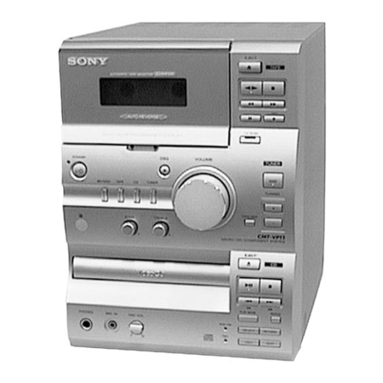
HCD-VP11 is the Amplifier, CD
player, Tape Deck and Tuner section
in CMT-VP11.
Dolby noise reduction manufactured under license
from Dolby Laboratories Licensing Corporation.
"DOLBY" and the double-D symbol a are trade-
marks of Dolby Laboratories Licensing Corporation.
TE
L 13942296513
www
.
http://www.xiaoyu163.com
Amplifier section
The following measured at 230 V AC, 60 Hz
DIN power output (rated): 30 + 30 W
(6 Ω at 1 kHz, DIN)
Continuous RMS power output (reference):
35 + 35 W
(6 Ω at 1 kHz, 10% THD)
The following measured at 220 V AC, 60 Hz
DIN power output (rated): 24 + 24 W
(6 Ω at 1 kHz, DIN)
Continuous RMS power output (reference):
27 + 27 W
(6 Ω at 1 kHz, 10% THD)
Inputs
MD IN (phono jacks):
Sensitivity 500 mV, impedance
47 kΩ
VIDEO IN (phono jacks): Sensitivity 250 mV, impedance
47 kΩ
MIC (mini jack):
sensitivity 1 mV,
impedance 10 kΩ
Outputs
LINE OUT (phono jacks): Sensitivity 250 mV, impedance
1 kΩ
OPTICAL DIGITAL OUT (CD):
Optical
VIDEO OUT (phono jack):
max. output level 1 Vp-p,
unbalanced, Sync negative, load
impedance 75 Ω
PHONES (stereo phone jack):
Accepts headphones with an
impedance of 8 Ω or more
x
ao
y
i
http://www.xiaoyu163.com
HCD-VP11
8
Model Name Using Similar Mechanism
CD Mechanism Type
CD
Section
Base Unit Name
Optical Pick-up Name
Model Name Using Similar Mechanism
Tape deck
Q Q
Section
Tape Transport Mechanism Type
3
6 7
1 3
SPECIFICATIONS
VIDEO CD/CD player section
System
Laser
Laser output
Wavelength
Video color system format
OPTICAL DIGITAL OUT (CD)
(Square optical connector jack, rear panel)
Wavelength
Output Level
MICRO Hi-Fi COMPONENT SYSTEM
u163
.
2 9
9 4
2 8
1 5
0 5
8
2 9
9 4
Compact disc and digital audio and
video system
Semiconductor laser
(λ=780 nm)
Emission duration: continuous
MAX 44.6 µ W*
* This output is the value
measured at a distance of
200 mm from the objective
lens surface on the optical
pick-up block with 7 mm
aperture.
780 - 790 nm
NTSC, PAL
660 nm
–18 dBm
— Continued on next page —
m
co
9 9
E Model
NEW
CDM55-K5BD42
BU-K5BD42
KSM-213CKP
HCD-CP11
TCB-020
2 8
9 9
Advertisement
Table of Contents

Subscribe to Our Youtube Channel
Related Manuals for Sony HCD-VP11


Summary of Contents for Sony HCD-VP11
- Page 1 E Model Note CD block, tape deck block and tuner pack are supplied with the assembled block. HCD-VP11 is the Amplifier, CD player, Tape Deck and Tuner section in CMT-VP11. Dolby noise reduction manufactured under license Model Name Using Similar Mechanism from Dolby Laboratories Licensing Corporation.
- Page 2 Frequency response (DOLBY NR OFF) 50 - 13,000 Hz (±3 dB), using a Sony TYPE I cassette 50 - 14,000 Hz (±3 dB), using a Sony TYPE II cassette Tuner section FM stereo, FM/AM superheterodyne tuner FM tuner section Tuning range 87.5 - 108.0 MHz...
-
Page 3: Table Of Contents
VIGYAZAT ! : A BURKOLAT NYITÁSAKOR LÁTHATATLAN LÉZERSU- LIST ARE CRITICAL TO SAFE OPERATION. REPLACE THESE GÁRVESZÉLY ! KERÜLJE A BESUGÁRZÁST ! COMPONENTS WITH SONY PARTS WHOSE PART NUMBERS APPEAR AS SHOWN IN THIS MANUAL OR IN SUPPLEMENTS PUBLISHED BY SONY. http://www.xiaoyu163.com... -
Page 4: General
http://www.xiaoyu163.com SECTION 2 GENERAL 3 7 63 1515 0 LOCATION OF CONTROLS 1 TAPE deck 2 Liquid crystal display • Front View 3 TAPE X button 4 TAPE m button 5 TAPE Y button 6 TAPE Z button 7 TAPE x button 8 TAPE M button 9 TAPE REC z button 0 CD SYNC button and indicator... - Page 5 http://www.xiaoyu163.com This section is extracted from instruction manual. 3 7 63 1515 0 Step 2: Setting the time Press ENTER. The clock will begin operating. Before you can use the system’s timer functions, set the internal clock. To reset the system clock You can reset the system clock even when the system is on or off.
-
Page 6: Disassembly
http://www.xiaoyu163.com SECTION 3 DISASSEMBLY 3 7 63 1515 0 Note: Follow the disassembly procedure in the numerical order given. 3-1. COVER (UPPER) 4 Cover (upper) 2 Four screws (BTP3 × 8) 1 Two screws (case3 TP2) 3 Two screws (case3 TP2) L 13942296513 3-2. - Page 7 http://www.xiaoyu163.com 3 7 63 1515 0 3-3. FRONT PANEL SECTION 2 Flat wire 1 Connector (CN303) 3 Connector 4 Screw (TP3 × 6) Two claws L 13942296513 6 Screw 5 Two screws (KTP3 × 6) (BTP3 × 8) 7 Front panel section (There is a claw.) u163 http://www.xiaoyu163.com...
- Page 8 http://www.xiaoyu163.com 3 7 63 1515 0 3-4. CD MECHANISM DECK 3 Screw (BTP3 × 8) 2 flat wire (19 core) (CN805) 1 connector 4 CD mechanism deck L 13942296513 3-5. UPPER CHASSIS 1 Screw 2 Upper chassis u163 http://www.xiaoyu163.com...
- Page 9 http://www.xiaoyu163.com 3 7 63 1515 0 3-6. TRAY 2 Belt 1 Rotate the control cam in 5 Pull the tray the direction of arrow A 4 Motor board L 13942296513 3 Two screws 3-7. CAM 3 Spacer (55) 4 Pulley 6 Gear 5 Gear 1 Torsion spring...
-
Page 10: Service Mode
http://www.xiaoyu163.com SECTION 4 SERVICE MODE 3 7 63 1515 0 [Liquid Crystal Display All Lit Check Mode] [CD Aging Mode] This mode can be used for operation check of CD section. Procedure: Set to standby state. Procedure: Press three buttons of x (TAPE), x (CD), and MD/VIDEO Load a CD disc. -
Page 11: Electrical Adjustments
http://www.xiaoyu163.com SECTION 5 ELECTRICAL ADJUSTMENTS 3 7 63 1515 0 Mode: Playback DECK SECTION 0 dB=0.775 V MAIN board test tape LINE OUT jack (PJ301) Note: Confirm each contents of this section first of all. If the results are L-CH P-4-A100 not satisfied, do the adjustment. - Page 12 http://www.xiaoyu163.com 3 7 63 1515 0 Playback Level Adjustment Record Level Adjustment Procedure: Procedure: Mode: FWD playback Record mode. test tape LINE IN P-4-L300 315Hz 50 mV (–23.8 dB) (3kHz, 0dB) frequency counter AF OSC blank tape 600 Ω CS-123 attenuator LINE OUT Playback mode.
-
Page 13: Diagrams
http://www.xiaoyu163.com SECTION 6 DIAGRAMS 3 7 6 3 1 5 1 5 0 NOTE FOR PRINTED WIRING BOARDS AND SCHEMATIC DIAGARAMS CD SECTION – CD BOARD (Conductor Side) – Note on Printed Wiring Board: Note on Schematic Diagram: • X : parts extracted from the component side. •... -
Page 14: Block Diagram - Main Section
HCD-VP11 6-2. BLOCK DIAGRAM – MAIN Section – 3 7 6 3 1 5 1 5 0 J402 MIC AMP MIC AMP R-CH IC315(1/2) IC315(2/2) RV200 LINE AMP PJ301 (2/2) ECHO IC307 LINE OUT MUTING Q101,107 R-CH PJ301 (1/2) -
Page 15: Block Diagram - Display/Power Supply Section
HCD-VP11 6-3. BLOCK DIAGRAM – DISPLAY/POWER SUPPLY Section – 3 7 6 3 1 5 1 5 0 SYSTEM CONTROLLER, D801 +5.6V LCD DRIVER BACK UP +5V REGULATOR IC801 (2/2) IC310 D802 SYSTEM CONTROLLER (IC801) B+ CD BLOCK VOLTAGE... -
Page 16: Printed Wiring Board - Main Section
HCD-VP11 6-4. PRINTED WIRING BOARD – MAIN Section – • See page 13 for Circuit Boards Location. There are few cases that the part printed on this 3 7 6 3 1 5 1 5 0 diagram isn’t mounted in this model. -
Page 17: Schematic Diagram - Main Section (1/2)
HCD-VP11 6-5. SCHEMATIC DIAGRAM – MAIN Section (1/2) – • See page 24 for IC Block Diagram. 3 7 6 3 1 5 1 5 0 1 3 9 4 2 2 9 6 5 1 3 w w w u 1 6 3 http://www.xiaoyu163.com... -
Page 18: Schematic Diagram - Main Section (2/2)
HCD-VP11 6-6. SCHEMATIC DIAGRAM – MAIN Section (2/2) – • See page 25 for IC Pin Function Description. • See page 13 for Waveforms. 3 7 6 3 1 5 1 5 0 PIN FUNCTION 1 3 9 4 2 2 9 6 5 1 3... -
Page 19: Printed Wiring Boards - Lcd/Headphone/Loading/Speaker Section
HCD-VP11 6-7. PRINTED WIRING BOARDS – LCD/HEADPHONE/LOADING/SPEAKER Section – 6-8. SCHEMATIC DIAGRAMS – HEADPHONE/SPEAKER Section – 3 7 6 3 1 5 1 5 0 • See page 13 for Circuit Boards Location. • See page 18 for LCD BOARD Schematic Diagram. -
Page 20: Printed Wiring Boards - Control Section
HCD-VP11 6-9. PRINTED WIRING BOARDS – CONTROL Section – • See page 13 for Circuit Boards Location. 3 7 6 3 1 5 1 5 0 There are few cases that the part printed on this diagram isn’t mounted in this model. -
Page 21: Schematic Diagram - Control Section
HCD-VP11 6-10. SCHEMATIC DIAGRAM – CONTROL Section – 3 7 6 3 1 5 1 5 0 – 1 3 9 4 2 2 9 6 5 1 3 w w w u 1 6 3 http://www.xiaoyu163.com... -
Page 22: Printed Wiring Board - Power Section
HCD-VP11 6-11. PRINTED WIRING BOARD – POWER Section – • See page 13 for Circuit Boards Location. There are few cases that the part printed on this 3 7 6 3 1 5 1 5 0 diagram isn’t mounted in this model. -
Page 23: Schematic Diagram - Power Section
HCD-VP11 6-12. SCHEMATIC DIAGRAM – POWER Section – 3 7 63 1515 0 L 13942296513 The components identified by mark 0 or dotted line with mark 0 are critical for safety. Replace only with part number specified. u163 http://www.xiaoyu163.com... -
Page 24: Ic Block Diagrams
http://www.xiaoyu163.com 3 7 63 1515 0 6-13. IC BLOCK DIAGRAMS – MAIN Board – IC101, 201 TDA7296 IC303 NJM3414AMP(TE2) THERMAL BIPOLAR SHUTDOWN TRANSCONDACTANCE INPUT STAGE MOS GAIN & SHORT – OUT1 OUTPUT CIRCUIT LEVEL SHIFTING STAGE STAGE PROTECTION –IN1 OUT2 +IN1 –IN2 STANDBY/... -
Page 25: Ic Pin Function Description
http://www.xiaoyu163.com 3 7 63 1515 0 6-14. IC PIN FUNCTION DESCRIPTION • MAIN BOARD IC801 CXP83120A-041Q (SYSTEM CONTROLLER, LCD DRIVER) Pin No. Pin Name Description TAPE-END Tape end detect sensor input terminal “H” input when the tape end detected Serial data reading clock signal input from the RDS decoder (IC804) RDS-CLK (Used for the AEP and UK models only) REMOCON... - Page 26 http://www.xiaoyu163.com 3 7 63 1515 0 Pin No. Pin Name Description Power supply on/off control signal output of the tuner pack (+7.5V) and RDS decoder (IC804) RDS-ON (RDS decoder: used for the AEP and UK models only) LED drive signal output of the TUNER indicator (D855) “H”: tuner power on (LED on) HP-CHK Headphone check detection signal input terminal TC-SW...
-
Page 27: Exploded Views
http://www.xiaoyu163.com SECTION 7 EXPLODED VIEWS 3 7 63 1515 0 NOTE: • -XX, -X mean standardized parts, so they may • Abbreviation The components identified by mark 0 or have some differences from the original one. : Singapore model. dotted line with mark 0 are critical for safety. •... - Page 28 http://www.xiaoyu163.com 3 7 63 1515 0 7-2. FRONT PANEL SECTION supplied supplied L 13942296513 supplied supplied with RV801 Ref. No. Part No. Description Remarks Ref. No. Part No. Description Remarks X-4952-336-1 KNOB ASSY 1-792-412-11 CABLE, FLEXIBLE FLAT (20 CORE) X-4952-749-1 PANEL SUB ASSY, FRONT 4-217-320-01 PLATE, BACK LIGHT 4-227-956-01 WINDOW (CASSETTE) X-4951-937-1 LOCK(EJECT) ASSY...
- Page 29 http://www.xiaoyu163.com 3 7 63 1515 0 7-3. CHASSIS SECTION EA,HK,SP,MY supplied supplied T901 supplied supplied supplied L 13942296513 supplied supplied Ref. No. Part No. Description Remarks Ref. No. Part No. Description Remarks 4-227-281-11 LID(CD) 1-677-146-21 SPEAKER BOARD 4-217-355-01 FOOT 0 112 1-556-091-00 CORD, POWER (TH) 4-217-354-01 BUSHING, INSULATING 0 112...
- Page 30 http://www.xiaoyu163.com 3 7 63 1515 0 7-4. CD MECHANISM DECK SECTION M901 L 13942296513 BU-K5BD41 Ref. No. Part No. Description Remarks Ref. No. Part No. Description Remarks 4-224-894-01 TRAY 4-221-815-01 ROLLER 4-220-229-01 LEVER (SW) X-4952-811-1 PULLEY (AT) ASSY 4-220-239-01 SPRING, TORSION 4-227-598-01 SPACER (55) 4-221-816-01 BELT (CDM55) 4-220-951-02 SHEET (KH)
- Page 31 http://www.xiaoyu163.com 3 7 63 1515 0 7-5. BASE UNIT SECTION L 13942296513 The components identified by mark 0 or dotted line with mark 0 are critical for safety. Replace only with part number specified. Ref. No. Part No. Description Remark A-4725-098-A CD BLOCK 0 202 8-848-483-05 OPTICAL PICK-UP KSM-213CKP/K1N...
-
Page 32: Electrical Parts List
http://www.xiaoyu163.com SECTION 8 CONTROL ELECTRICAL PARTS LIST 3 7 63 1515 0 NOTE: • Due to standardization, replacements in the • RESISTORS • Abbreviation parts list may be different from the parts All resistors are in ohms. : Singapore model. specified in the diagrams or the components METAL: metal-film resistor : Malaysia model. - Page 33 http://www.xiaoyu163.com CONTROL HEADPHONE LOADING MAIN 3 7 63 1515 0 Ref. No. Part No. Description Remarks Ref. No. Part No. Description Remarks < VARIABLE RESISTOR > < VARIABLE RESISTOR > RV801 1-473-392-11 ENCODER, ROTARY (VOLUME) RV200 1-225-916-11 RES, VAR, CARBON 20K (MIC VOL) RV802 1-418-859-11 ENCODER, ROTARY (TREBLE) ************************************************************...
- Page 34 http://www.xiaoyu163.com MAIN 3 7 63 1515 0 Ref. No. Part No. Description Remarks Ref. No. Part No. Description Remarks C106 1-126-963-11 ELECT 4.7uF 20.00% 50V C311 1-126-955-11 ELECT 4700uF 20.00% 35V C107 1-163-022-00 CERAMIC CHIP 0.012uF C312 1-126-942-61 ELECT 1000uF 20.00% 25V C109 1-126-963-11 ELECT...
- Page 35 http://www.xiaoyu163.com MAIN 3 7 63 1515 0 Ref. No. Part No. Description Remarks Ref. No. Part No. Description Remarks < CONNECTOR > Q201 8-729-920-31 TRANSISTOR DTC343TK Q202 8-729-920-31 TRANSISTOR DTC343TK * CN306 1-568-954-11 PIN, CONNECTOR 5P Q203 8-729-920-31 TRANSISTOR DTC343TK * CN315 1-568-936-11 PIN, CONNECTOR 9P Q206...
- Page 36 http://www.xiaoyu163.com MAIN 3 7 63 1515 0 Ref. No. Part No. Description Remarks Ref. No. Part No. Description Remarks R123 1-216-045-00 METAL CHIP 1/10W R316 1-216-033-00 METAL CHIP 1/10W R123 1-216-091-00 METAL CHIP 1/10W R317 1-216-053-00 METAL CHIP 1.5K 1/10W R124 1-216-081-00 METAL CHIP 1/10W...
- Page 37 http://www.xiaoyu163.com MAIN POWER 3 7 63 1515 0 Ref. No. Part No. Description Remarks Ref. No. Part No. Description Remarks R822 1-216-049-91 RES-CHIP 1/10W R877 1-216-065-91 RES-CHIP 4.7K 1/10W R823 1-216-049-91 RES-CHIP 1/10W R878 1-216-065-91 RES-CHIP 4.7K 1/10W R824 1-216-049-91 RES-CHIP 1/10W R879 1-216-065-91 RES-CHIP...
- Page 38 HCD-VP11 POWER SPEAKER VIDEO OUT 3 7 63 1515 0 Ref. No. Part No. Description Remarks Ref. No. Part No. Description Remarks < FUSE > < JACK > 0 F901 1-533-464-11 FUSE, GLASS TUBE (DIA. 5) 0.8A/250V J401 1-793-571-11 JACK, PIN (VIDEO OUT) 0 F902 1-533-468-11 FUSE, GLASS TUBE (DIA.
Need help?
Do you have a question about the HCD-VP11 and is the answer not in the manual?
Questions and answers