Table of Contents
Advertisement
INSTALLATION
OPERATING
INSTRUCTIONS
f i r e - p a r t s . c o m
WARNING: If the information in this manual is not followed exactly, a fire or
explosion may result causing property damage, personal injury or loss of life.
-- Do not store or use gasoline or other flammable vapors and liquids in the
vicinity of this or any other appliance.
-- WHAT TO DO IF YOU SMELL GAS
- Do not try to light any appliance.
- Do not touch any electrical switch; do not use any phone in your building.
- Immediately call your gas supplier from a neighbour's phone. Follow the
gas supplier's instructions.
- If you cannot reach your gas supplier, call the fire department.
--Installation and service must be performed by a qualified installer, service
agency or the gas supplier.
IMPORTANT: THESE INSTRUCTIONS ARE TO REMAIN WITH THE HOMEOWNER
200598-24
AND
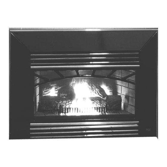
DIRECT VENT
FIREPLACE INSERT
DVI-INST
Direct Vent Insert
SERIES A
# 5055.65
Advertisement
Table of Contents

Related Manuals for Mirage SERIES A

Summary of Contents for Mirage SERIES A
- Page 1 Direct Vent Insert INSTALLATION OPERATING INSTRUCTIONS SERIES A f i r e - p a r t s . c o m DIRECT VENT FIREPLACE INSERT WARNING: If the information in this manual is not followed exactly, a fire or explosion may result causing property damage, personal injury or loss of life.
-
Page 2: Table Of Contents
Contents Caution ..................3 Safety ..................3 Maintenance................3 Installation ................. 4 Clearances .................. 5 Venting ..................6 Rocker Switch................7 Gas Supply ................. 8 Burner Assembly ............... 8 Brick Panels Installation............10 Levelling Legs ................. 10 Log Set ..................11 Surround Assembly .............. -
Page 3: Caution
FOR YOUR SAFETY - Do not install or operate your Pacific Caution: Turn off gas and electrical power supply and allow Energy Mirage Direct Vent Gas Insert without first reading ample time for unit to cool before servicing appliance. It is and understanding this manual. -
Page 4: Installation
Existing Fireplace (Masonry or Factory Built) The Mirage Direct Vent Gas Insert is designed to be installed into a masonry or a factory built zero clearance fireplace. The masonry fireplace must be built according to the require-... -
Page 5: Clearances
Clearances Fig. # 5 The minimum clearances from the appliance to combustible surfaces are shown on Fig. #4 and #5. Adequate clearances around air openings and combustion air supplies are required. MINIMUM CLEARANCES TO COMBUSTIBLES: Adjacent sidewall: .......6.0 in. (152 mm) Ceiling to appliance: .....50 in. -
Page 6: Venting
Venting Fig # 7 Vent Terminal Caution: Only Flex Liner kit (MIND.FL25) or an approved Seal gas vent flue liner and a Vent Terminal (MIND.VTTERM) is approved for use with this appliance. Also approved for use is Simpson Dura-Vent GS termination kits, both Standard Vertical Termination cap (#980) and the Extended Vertical Termination cap (#930) in conjunction with the 3"... -
Page 7: Rocker Switch
Make sure the marked inlet pipe is attached to the inlet side (marked "I"), and the unmarked pipe is attached to the Fig # 9 outlet side (marked "E") of the connector plate. 7) Seal and secure inlet pipe with sealant and screws pro- vided. -
Page 8: Gas Supply
1) Fold down the bottom louver, if installed, to access the The Mirage Direct Vent Gas Insert comes equipped with a over-center latch. Disengage the latches by pulling each flexible connector with a 3/8" N.P.T. Male inlet for easy gas lever down and forward. - Page 9 7) Once positioned inside the firebox and Fig # 13 properly seated on the ledge, push the burner assembly back and secure in place with wing nuts provided. (Fig. #12) 8) Fasten rear burner bracket to firebox back with screws provided. (Fig. # 13) 9) Connect the wire harness from the rocker switch to the control valve ter- minal marked "TH"...
-
Page 10: Brick Panels Installation
Brick Panels Installation Levelling Legs The panels for the firebox are shipped in a separate cardboard Levelling legs are provided with the appliance as a conven- box located inside the appliance. Carefully remove the panels ient means for levelling the appliance when it is installed on from the box and install them as follows: an irregular surface. -
Page 11: Log Set
Log Set Fig. #16 The Ceramic logs are durable and long lasting when installed properly. However, they are delicate and may be damaged easily if not handled with care. Unpack and inspect log set. Back Log There should be a total of 4 logs as shown in Fig. # 16. All gas and venting connections should be made before installing log set. -
Page 12: Surround Assembly
Surround Assembly Fig. # 18 Fig. # 19 1) Lay Parts A, B, and C face down on a flat, non-marking surface. (Fig. #17) Fasten together with spring clips through holes at points "D". (Fig. #20) 2) Lift the surround assembly to the upright position and make sure the front face is even at the joint. -
Page 13: First Fire
NEVER be set to create sooting on internal parts and glass. the HI-LO burner control knob to a desired setting. As heat Open air shutter gradually until sooting stops. is required, the Mirage Gas Insert will turn on or off automati- cally, as needed. Fig. # 24... -
Page 14: For Your Safety Read Before Lighting
FOR YOUR SAFETY READ BEFORE LIGHTING phone in your building. WARNING: If you do not follow these - Immediately call your gas supplier from a neigh- instructions exactly, a fire or explosion bour's phone. Follow the gas supplier's instruc- may result causing property damage, tions. -
Page 15: Optional Blower
Optional Blower Fig. # 26 Optional Blower Studs Electrical Supply: Circulating air blower electrical rating: 115V, 60 Hz, 80 watts. (Fig #25) For your protection against shock hazard, use only a properly grounded outlet that will accept a three-pronged plug. Do not cut or remove the grounding prong. -
Page 16: Replacement Parts
Replacement Parts Fig. # 28 (WHEN ORDERING, INCLUDE PART NUMBER WITH DESCRIPTION) ITEM DESCRIPTION PART NO. ITEM DESCRIPTION PART NO. 1 ..Main Body ........MIND.1800 15 ..Brick Panel, Right ....... MIND.509771 2 ..Baffle ..........MIND.1834 16 ..Surround Trim, Left ......MINC.1664 3 .. - Page 17 Fig. # 28 f i r e - p a r t s . c o m...
-
Page 18: Glass Frame Removal
Glass Frame Removal Optional Radiant Overlay The glass frame is designed with quick release catches for The optional Radiant Overlay may be installed at any time. easy removal. The frame is held in place by two over-center Unpack and inspect all parts. Install Overlay as follows: latches located under the firebox. -
Page 19: Vent Terminal Kit
Vent Terminal MIND.VTTERM Direct Vent Insert This vent kit is for use with the model MIRAGE DVI, Series A gas insert only. Please refer to the Installation Instructions provided with the appliance for proper installation. This box contains: 1 ..Vent Terminal f i r e - p a r t s . -
Page 20: Vent Terminal Flashing Installation Guide
Vent Terminal Flashing Installation Guide Direct Vent Insert Vent Terminal MIND.FLASH This kit contains: 1 ..Vent Terminal Flashing 4 ..#8 x 1" Sheet Metal Screws f i r e - p a r t s . c o m Installation: Attach the vent terminal to the flashing Attach the flashing to the chimney, by first... -
Page 21: Optional Blower Kit
Optional Blower Kit MIND.BLOW Direct Vent Insert This kit contains: 1 ..Blower assembly (including blower, control box, and power cord) f i r e - p a r t s . c o m 2 ..Wing nuts 2 ..#8 x 1/2 Sheet metal screws (black in color) Installation: Please see instruction manual... -
Page 22: Louver Kit Installation Guide
Louver Kit Installation Guide Black Louver MINC.BKLVR Gas Insert Gold Louver MINC.GDLVR This kit contains: 1 ..Top Louver (Black or Gold) 1 ..Bottom Louver (Black or Gold) f i r e - p a r t s . c o m 4 ..#8 x 1/2"... -
Page 23: Safety Label
ANS Z21.44 -1995 Direct Vent Wall Furn., CAN1-2.19 -M81 Direct Vent Wall Furnace, CAN/CGA-2.17 -M91 Gas-Fired Applainces For Use At High Altitudes, CGA I.R. #41 - 1991 and #55 Rev.1 - 1995 MIRAGE - DIRECT VENT INSERT MODEL / MODELE: SERIES / SERIE:... - Page 24 f i r e - p a r t s . c o m Pacific Energy Fireplace Products Ltd. Box 1060, Duncan, B.C. V9L 3Y2 Phone: 250-748-1184 Web site: http://www.pacificenergy.bc.ca Printed in Canada...