Table of Contents
Advertisement
Quick Links
Advertisement
Table of Contents

Related Manuals for Thrane&Thrane SAILOR 900


Summary of Contents for Thrane&Thrane SAILOR 900
- Page 1 INSTALLATION & USER MANUAL SAILOR 900 VSAT System...
- Page 3 SAILOR 900 VSAT Installation and user manual Document number: 98-133400-B Release date: 8 November 2011...
- Page 4 2800 Lyngby DENMARK Please write "source for product SAILOR 900 VSAT" in the memo line of your payment. You may also find a copy of the source at http://www.thrane.com/foss. This offer is valid to anyone in receipt of this information.
-
Page 5: Safety Summary
Safety summary The following general safety precautions must be observed during all phases of operation, service and repair of this equipment. Failure to comply with these precautions or with specific warnings elsewhere in this manual violates safety standards of design, manufacture and intended use of the equipment. - Page 6 Power supply The voltage range for the SAILOR 900 VSAT is 20 — 32 VDC. Note that the Above Deck Unit is powered by the ACU. If a 24 VDC power bus is not available, an external 115/230 VAC to 28 VDC power supply can be used, for example a SAILOR 6080 Power Supply.
- Page 7 Record of Revisions Rev. Description Release Date Initials Original document 26 September 2011 The following sections have been added: 6.3.6, 6.3.7, 8 November 2011 6.3.8, 9.4, Appendix B, Appendix C. The following sections have been edited: 1.2, 3.1.1, 3.2.6 (p. 3-10) 3.6.1, 4.1.7, 6.2.2, 6.3, 9.1.1. The following figures have been added: 6-3, A-1, A-2, The following figures have been edited: 2-4, 2-5, 6-4, 6-5, 6-6, 6-7, 6-14, 8-1, 9-10, 9-11.
- Page 8 98-133400-B...
-
Page 9: Table Of Contents
2.1.6 Service activation ................2-9 Part numbers and options ............... 2-10 2.2.1 Applicable Thrane & Thrane model- and part numbers ....2-10 2.2.2 Options for SAILOR 900 VSAT ............2-10 Chapter 3 Installation Unpacking ..................3-1 3.1.1 What’s in the box ................3-1 3.1.2... - Page 10 3.4.1 Installing the ACU (bulkhead) ............3-23 3.4.2 Grounding the ACU (bulkhead) ............. 3-24 3.4.3 SAILOR 900 VSAT ACU (bulkhead) with cable support ....3-24 Installation of the 19” rack version of the ACU ........ 3-26 3.5.1 Installing the 19” rack version of the ACU ........3-26 3.5.2 Grounding the 19”...
- Page 11 6.3.7 Sending statistics reports ..............6-24 6.3.8 Sending a diagnostic report ............6-27 6.3.9 Upload ..................6-28 6.3.10 Administration ................6-28 Keypad of the SAILOR 900 VSAT ACU ..........6-33 6.4.1 ACU display and keypad ..............6-33 6.4.2 Navigating the menus ..............6-34 6.4.3 The menu tree ................6-35 6.4.4 Adjusting brightness of the display ..........6-39...
- Page 12 Removal and replacement of the ACU ..........9-11 Removal and replacement of ADU modules ........9-12 Initial troubleshooting ..............9-15 9.6.1 Viewing the Event list ..............9-15 Appendix A Technical specifications SAILOR 900 VSAT system components ..........A-1 A.1.1 General specifications ..............A-1 A.1.2 ADU ....................A-2 A.1.3 ACU ....................A-4 A.1.4...
- Page 13 Table of Contents Non-Open-AMIP setup for iDirect iNFINITI 5000 & Evolution X5 ..C-10 C.2.1 Protocol and interfaces ..............C-10 C.2.2 Console port settings ..............C-11 C.2.3 Configuration examples (Non-OpenAMIP) ........C-13 Setup of Comtech 570L, ROSS box & ACU ........C-14 C.3.1 Protocols and interfaces ..............
- Page 14 Table of Contents Glossary ......................Glossary-1 Index ......................... Index-1 98-133400-B...
- Page 15 Mounting the ADU on the mast flange..............3-20 Figure 3-18: Connecting the ADU cable .................. 3-21 Figure 3-19: ACU, connector panel ..................3-23 Figure 3-20: SAILOR 900 VSAT ACU, bulkhead version, ground stud ........3-24 Figure 3-21: Mounting the cable relief 1/2 ................3-25 98-133400-B xiii...
- Page 16 Chapter 6 Configuration Figure 6-1: Configuration setup....................6-1 Figure 6-2: LAN connector used for configuring the SAILOR 900 VSAT ........6-2 Figure 6-3: SAILOR 900 VSAT Dashboard ................6-3 Figure 6-4: Service profile, add a Service ‘modem’ for calibration ..........6-4 Figure 6-5: Service profile, add satellite information ..............6-5...
- Page 17 Chapter 7 Installation check Chapter 8 Daily use — Quick guide Figure 8-1: SAILOR 900 VSAT Quick Guide — web interface and satellite profiles ....8-1 Figure 8-2: SAILOR 900 VSAT Quick Guide — Viewing system parameters .......8-2 Chapter 9 Service Figure 9-1: Web interface: HELPDESK ..................9-2...
- Page 18 List of Figures App. B VMU cable specifications Figure B-1: Modem Cable Comtech Serial & RSSI TT7016A.............B-2 Figure B-2: Modem Cable iNIFINITI iDirect VSAT modem............B-3 App. C VMU settings requirements Figure C-1: Connecting iDirect iNFINITI 5000 series to the ACU (OpenAMIP) ......C-3 Figure C-2: Connecting iDirect Evolution X5 to the ACU (OpenAMIP) ........C-3 Figure C-3:...
- Page 19 Introduction Table 2-1: Model and part numbers for the SAILOR 900 VSAT system (T&T units)....2-10 Table 2-2: Model and part numbers for options of the SAILOR 900 VSAT system ....2-10 Chapter 3 Installation Table 3-1: Maximum distance from the ship’s motion center versus ship’s roll period...3-7 Table 3-2: Mast dimensions without braces .................
- Page 20 List of Tables Table 6-6: Parameters recorded in a statistics report ............6-25 Table 6-7: Items in the ACU display (Example)..............6-33 Table 6-8: Top-level menus of the ACU ................6-36 Table 6-9: ANTENNA menu of the ACU................6-37 Table 6-10: MODEM menu of the ACU ..................
-
Page 21: Chapter 1 About This Manual
About this manual Intended readers This is an installation and user manual for the SAILOR 900 VSAT system, intended for installers of the system and service personnel. Personnel installing or servicing the system must be properly trained and authorized by Thrane & Thrane. It is important that you observe all safety requirements listed in the beginning of this manual, and install the system according to the guidelines in this manual. -
Page 22: Related Documents
The following related documentation is referred to in this manual: Document number Title 98-133401 SAILOR 900 VSAT Quick guide Table 1-1: List of Related Documents Typography In this manual, typography is used as indicated below: Bold is used for the following purposes: •... - Page 23 Precautions General precautions All personnel who operate equipment or do maintenance as specified in this manual must know and follow the safety precautions. The warnings and cautions that follow apply to all parts of this manual. WARNING! Before using any material, refer to the manufacturers’...
-
Page 24: Chapter 1 About This Manual
Precautions Chapter 1: About this manual 98-133400-B... -
Page 25: Chapter 2 Introduction
• Part numbers and options SAILOR 900 VSAT system The SAILOR 900 VSAT is a unique stabilized maritime VSAT antenna system operating in the Ku-band (10.7 to 14.5 GHz). It provides bi-directional IP data connections both on regional satellite beams and quasi-global Ku-band satellite networks. The system only requires a single 50 Ohm cable to provide the Above Deck Unit with both DC power, data and control information. -
Page 26: Chapter 2 Introduction
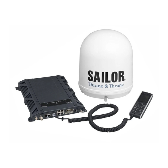
SAILOR 900 VSAT system The following figures show the SAILOR 900 VSAT system with its two variants of ACUs. Above Deck Unit (ADU) Antenna Control Unit (ACU) Figure 2-1: Above Deck Unit and Antenna Control Unit (ACU) Above Deck Unit (ADU) Antenna Control Unit (ACU) (1 U 19”... -
Page 27: Above Deck Unit (Adu)
2.1.1 Above Deck Unit (ADU) The SAILOR 900 VSAT Above Deck Unit is a 103 cm VSAT stabilised tracking antenna, consisting of a suspended antenna with a standard global RF configuration. The Above Deck Unit’s weight is around 135 kg. It is stabilized by heavy duty vibration dampers in 3-axis (plus skew) and can be used in environments with elevations of -25°... -
Page 28: Figure 2-4: Above Deck Unit Modules 1/2
SAILOR 900 VSAT system Modules in the SAILOR 900 VSAT Above Deck Unit Figure 2-4: Above Deck Unit modules 1/2 1. GPS module. 2. VSAT Interface Module (VIM). 3. DC-Motor Driver Module for cross elevation (DDM). 4. Cross elevation motor and encoder. -
Page 29: Chapter 2 Introduction
SAILOR 900 VSAT system 10. Block Up Converter (BUC). (behind cable screen, not visible on photo) 11. Low Noise Block downconverter (x2) (LNB). (not visible on photo) 12. Ortho Mode Transducer (OMT). (not visible on photo) 13. Inertial Sensor Module (ISM). -
Page 30: Antenna Control Unit (Acu)
SAILOR 900 VSAT system SAILOR 900 VSAT Above Deck Unit interface All communication between the Above Deck Unit and the ACU passes through a single standard 50 Ohm cable (with N connector) through the rotary joint. No cable work is required inside the radome. -
Page 31: Figure 2-6: Sailor 900 Vsat Acu, Connector Overview
The 19” rack version of the ACU has additionally a LAN connector at the front for accessing the service port from the ACU front panel. Service port Figure 2-7: SAILOR 900 VSAT ACU, 19” rack version 98-133400-B Chapter 2: Introduction... -
Page 32: Figure 2-8: Antenna Control Unit For Bulkhead Installation
SAILOR 900 VSAT system Installation friendly The ACU comes in two models: Wall or desktop installation (bulkhead) or in a 19” rack version. Figure 2-8: Antenna Control Unit for bulkhead installation Figure 2-9: Antenna Control Unit for 19” rack installation Service friendly You can do remote diagnostics and service with the ACU. -
Page 33: Vsat Modem Unit (Vmu)
ESUPPORT. 2.1.4 Satellite type approvals For a list of satellite type approvals see the SAILOR 900 VSAT data sheet at thrane.com. 2.1.5 Power supply To provide DC power to the SAILOR 900 VSAT you can use the TT-6080A Power Supply. -
Page 34: Part Numbers And Options
Part numbers and options Part numbers and options 2.2.1 Applicable Thrane & Thrane model- and part numbers This Installation Manual is for the SAILOR 900 VSAT system and is applicable to the model- and part numbers below: T&T part number Model number Description... -
Page 35: Chapter 3 Installation
• Installation of the VMU Unpacking 3.1.1 What’s in the box Unpack your SAILOR 900 VSAT ADU and check that the following items are present: • ADU with 4 lifting brackets (already mounted) • Package with bolts and washers ACU (bulkhead) -
Page 36: Initial Inspection
Unpacking ACU (19” rack version) Unpack your SAILOR 900 VSAT ACU (19” rack version) and check that the following items are present: • 1 x Ethernet cable (2 m) • 1 x Ethernet cable (short) • Power connector • 2 x 75 Ohm coax cables F-F (1m), for Rx and Tx •... -
Page 37: Site Preparation
For optimum system performance, some guidelines on where to install or mount the different components of the SAILOR 900 VSAT System must be followed. It is recommended to mount the ADU in a location with as much 360° free line of sight to the satellite as possible while making sure that the support structure fulfills the requirements for the mast foundation. -
Page 38: Figure 3-1: Signal Degradation Because Of Obstructing Objects
Site preparation large objects that may block the signal. To avoid obstruction elevate the ADU by mounting it on a mast or on a mounting pedestal on a deck or deck house top. Look angle: - 25° to +125° Obstruction Figure 3-1: Signal degradation because of obstructing objects The ADU is stabilized in 3-axis (plus skew) and can be used in environments with elevations of -25°... -
Page 39: Blocking Zones - Azimuth And Elevation
Elevation: - 25° to +30° Figure 3-3: Blocking zone with no-transmit zones, elevation angle (example) The blocking zones are set up in the SAILOR 900 VSAT built-in web interface. For further information see Setting up Blocking zones (RX and TX) on page 6-19. -
Page 40: Safe Access To The Adu: Radiation Hazard
Safe access to the ADU: Radiation hazard The SAILOR 900 VSAT ADU radiates up to 49 dBW EIRP. This translates to a minimum safety distance of 30 m from the ADU while it is transmitting, based on a radiation level... -
Page 41: Ship Motion And Offset From The Ship's Motion Centre
Site preparation 3.2.5 Ship motion and offset from the ship’s motion centre Even though it is recommended to mount the ADU high, keep the distance between the ADU and the ship’s motion centre as short as possible. The higher up the ADU is mounted, the higher is the linear g force applied to the ADU. -
Page 42: Adu Mast Design: Foundation And Height
Site preparation 3.2.6 ADU mast design: Foundation and height The ADU mast must be designed to carry the weight of the ADU unit, which is approximately 135 kg (+ the weight of the mast flange). The mast must also be able to withstand onboard vibrations and wind speeds up to 110 knots on the radome, even in icing conditions. -
Page 43: Figure 3-8: Adu Mast Flange, Distance To The Welded Seam
Site preparation Allow sufficient space so the nut is free of the welded seam and there is room for tools . Clearance hole for M12 bolts Figure 3-8: mast flange, distance to the welded seam CAUTION! Avoid sharp edges where the flange is in direct contact with the radome. -
Page 44: Figure 3-10: Free Mast Length And Bracing For A Tall Mast
Site preparation Mast length and diameter The placement of the ADU must ensure a rigid structural connection to the hull or structure of the ship. Parts of the ship with heavy resonant vibrations are not suitable places for the ADU. A small platform or short mast shall provide rigid support for the ADU fastening bolts and a rigid interface to the ship. -
Page 45: Table 3-2: Mast Dimensions Without Braces
Site preparation SAILOR 900 VSAT ADU mast length The below tables show the minimum dimensions for a SAILOR 900 VSAT ADU mast with and without stays or wires. Note that the values are only guidelines - always consider the environment and characteristics of the ship before deciding on the mast dimensions. -
Page 46: Table 3-4: Mast Dimensions With 2 Braces
Site preparation Max. free Outer Outer Wall Thickness mast Diameter Mast with 2 braces Diameter Thickness for brace length (steel), for brace (mm) (mm) (mm) (mm) Table 3-4: Mast dimensions with 2 braces 3-12 Chapter 3: Installation 98-133400-B... -
Page 47: Interference
ADU performance. RF emission from radars might actually damage the ADU. The SAILOR 900 VSAT ADU itself may also interfere with other radio systems. Radar It is difficult to give exact guidelines for the minimum distance between a radar and the ADU because radar power, radiation pattern, frequency and pulse length/shape vary from radar to radar. -
Page 48: Table 3-5: Minimum Radar Separation, X-Band
“d min.” is defined as the shortest distance between the radar antenna (in any position) and the surface of the SAILOR 900 VSAT ADU. X-band (~ 3 cm / 10 GHz) damage distance SAILOR 900 VSAT ADU Radar d min. - Page 49 Even at distances greater than “d min.” in the previous section the radar might still be able to degrade the performance of the SAILOR 900 VSAT system. The presence of one or more S or X-band radars within a radius up to 100 m may cause a minor degradation of the Ku-band connection.
-
Page 50: Figure 3-12: Recommended Distance To Transmitters (M) For Frequencies Below 1000 Mhz
Site preparation Other transmitters See the following figure for minimum recommended distance to transmitters in the frequency range below 1000 MHz. Distance to transmitters (m) Figure 3-12: Recommended distance to transmitters (m) for frequencies below 1000 MHz 3-16 Chapter 3: Installation 98-133400-B... -
Page 51: Other Precautions
Site preparation 3.2.8 Other precautions Condensation and water intrusion If possible, install the radome such that direct spray of seawater is avoided. In some weather condition there may occur condensation inside the radome. The drain tube is designed to lead any water away from inside the radome. Make sure the ADU’s drain tube is open and that there it free space between the drain tube and the mounting surface so water can escape and there is ventilation for the ADU. -
Page 52: Installation Of The Adu
Installation of the ADU Installation of the ADU The ADU is shipped fully assembled. You have to install it on the mast and attach the ADU cable. WARNING! Use a strong webbed sling with a belt to lift the ADU without damaging the radome. Make sure that the sling can carry the ADU’s weight (135 kg, 288 lbs). -
Page 53: Installing The Adu
Figure 3-15: Free space for access to the service hatch The ADU does not have to be aligned with the bow-to-stern line of the ship. When configuring the SAILOR 900 VSAT you make an azimuth calibration to obtain the correct azimuth of the ADU. -
Page 54: Figure 3-16: Adu Installation, Webbed Sling Attached To The 4 Lifting Brackets
Installation of the ADU 4. Attach a webbed, four-part sling with a belt to all 4 lifting brackets. Figure 3-16: ADU installation, webbed sling attached to the 4 lifting brackets 5. Attach 2 tag lines of suitable length to 2 lifting brackets and man them. 6. -
Page 55: Figure 3-18: Connecting The Adu Cable
Installation of the ADU 8. Put the coaxial ADU cable through the protection plate as shown in the following figure, and connect the N connector of the ADU cable to the ADU (see picture series below). Protection plate N connector Figure 3-18: Connecting the ADU cable Ensure that the connector assembly is properly protected against seawater and corrosion. -
Page 56: Grounding The Adu
Installation of the ADU 3.3.2 Grounding the ADU The ADU must be grounded using the mounting bolts. If the ADU cannot or should not be electrically connected directly to the mounting surface, you can use a separate grounding cable to make the connection between the ADU and the common ground to which the ACU is also connected. -
Page 57: Installation Of The Acu (Bulkhead)
3-24 and the appendix Grounding and RF protection on page D-1 for details about grounding. 3. Connect all cables. See Interfaces of the SAILOR 900 VSAT ACU on page 4-1 for a description of the ACU connectors. 4. Secure the cables using cable strips. -
Page 58: Grounding The Acu (Bulkhead)
(minimum cross section: 4 mm Ground stud Figure 3-20: SAILOR 900 VSAT ACU, bulkhead version, ground stud 3.4.3 SAILOR 900 VSAT ACU (bulkhead) with cable support You can mount a Cable Relief for the ACU (bulkhead). -
Page 59: Figure 3-21: Mounting The Cable Relief 1/2
Installation of the ACU (bulkhead) To mount the cable relief, do as follows: 1. Remove the two rubber washers from the bottom of the ACU at the connector panel end. The threaded bushings underneath the rubber washers are used for mounting the cable support. -
Page 60: Installation Of The 19" Rack Version Of The Acu
3-24 and the appendix Grounding and RF protection on page D-1 for details about grounding. 5. Connect all cables. See Interfaces of the SAILOR 900 VSAT ACU on page 4-1 for a description of the ACU connectors. 6. Secure the cables to the cable relief using cable strips. -
Page 61: Grounding The 19" Rack Version Of The Acu
Installation of the 19” rack version of the ACU Connectors of the 19” rack version of the ACU For a description of the connectors see Connectors of the ACU on page 3-23. The 19” rack version of the ACU has additionally a LAN connector at the front for accessing the service port from the ACU front panel. -
Page 62: Installation Of The Vmu
Installation of the VMU Installation of the VMU For a list of supported VSAT modems see the SAILOR 900 VSAT data sheet. For the latest status of supported VMUs see http://extranet.thrane.com/ and click ESUPPORT. 3.6.1 General mounting considerations — VMU 1. -
Page 63: Chapter 4 Interfaces
Chapter 4 Interfaces This chapter is organised in the following sections: • Interfaces of the SAILOR 900 VSAT ACU • Interfaces of the VMU Interfaces of the SAILOR 900 VSAT ACU 4.1.1 ACU bulkhead — LEDs, display and keypad Figure 4-1: ACU bulkhead, LEDs, display and keypad 4.1.2... -
Page 64: Acu Bulkhead - Connector Panel - Overview
Interfaces of the SAILOR 900 VSAT ACU 4.1.3 ACU bulkhead — Connector panel — overview LAN 2 Rx Out Tx in RS-422 LAN 1 Modem Ctrl. Modem Ctrl. NMEA RS-232 LAN 3 LAN 4 Power On/Off Service port Figure 4-3: ACU bulkhead, connector panel overview 4.1.4... -
Page 65: Dc Input Connector
Interfaces of the SAILOR 900 VSAT ACU 4.1.5 DC Input connector Provide DC power to the ACU, for example by using the TT-6080A Power Supply or 24 VDC from the vessel’s power supply. DC input: Female plug (Weidmuller, Part number 1930050000) for wires up to... -
Page 66: Adu Connector
Interfaces of the SAILOR 900 VSAT ACU 4.1.6 ADU connector There is just one cable from the ACU to the ADU. This is used to power the ADU, supply 10 MHz clock, handle all communication between ACU and ADU, and deliver the VSAT Rx and Tx signals. -
Page 67: Nmea 0183/2000 Connector
Interfaces of the SAILOR 900 VSAT ACU 4.1.8 NMEA 0183/2000 connector (Prepared for NMEA 2000) Connect the ship’s gyro to this connector. Wire Outline numbe Pin function color — — NET-H (NMEA White 2000) NET-L (NMEA 2000) Blue NET-S (NMEA 2000) -
Page 68: And Rs-422 Connectors
Interfaces of the SAILOR 900 VSAT ACU • Propagation delay: 5 nanoseconds per meter, maximum • 15 Twists (minimum) per meter 4.1.9 RS-232 and RS-422 connectors These connectors are used to access and configure the connected VSAT modem and for ACU control. -
Page 69: Lan1, Lan2, Lan3 And Lan4 Connectors
Interfaces of the SAILOR 900 VSAT ACU Outline Pin function number Ground Line A RXD (+) Line B TXD (-) Ground Ground — Line A RXD (-) Line B TXD (+) — Table 4-6: RS-422 connector, male, outline and pin assignment 4.1.10... -
Page 70: Table 4-7: Ethernet Connector, Outline And Pin Assignment
Interfaces of the SAILOR 900 VSAT ACU Outline numbe Pin function Wire color white/orange orange white/green Not connected blue Not connected white/blue green Not connected white/brown Not connected brown Table 4-7: Ethernet connector, outline and pin assignment Cable type: CAT5, shielded. -
Page 71: Interfaces Of The Vmu
Interfaces of the VMU Interfaces of the VMU For interfaces of the VMU and how to connect a VMU correctly to the ACU see the following sections and the user documentation of the VMU. 4.2.1 Connecting an iNFINITI® 5000 Series Satellite Router Connect the VSAT modem to the ACU as shown in the figure below: Antenna Antenna... -
Page 72: Connecting An Evolution® X5 Satellite Router
Interfaces of the VMU 4.2.2 Connecting an Evolution® X5 Satellite Router Connect the VSAT modem to the ACU as shown in the figure below: Antenna Antenna Rx Out RS-232 LAN 1 Tx In Rx In Console Tx Out Evolution X5 Satellite Router Figure 4-8: Connecting an Evolution X5 Satellite Router Cable 3 is only used when using OpenAMIP protocol. -
Page 73: Connecting A Comtech 570 L Or 625 Satellite Modem
Interfaces of the VMU 4.2.3 Connecting a Comtech 570 L or 625 Satellite Modem Connect the VSAT modem to the ACU as shown in the figure below: Antenna Antenna Rx Out RS-232 Tx In Alarms Remote control 950-1950 MHz 950-1950 MHz Comtech 570 L-Band Satellite Modem Figure 4-9: Connecting a Comtech 570 L or 625 Satellite Modem Cable... - Page 74 Interfaces of the VMU 4-12 Chapter 4: Interfaces 98-133400-B...
-
Page 75: Chapter 5 Connecting Power
Chapter 5 Connecting power This chapter is organised in the following sections: • Power source • Power cable selection • Connecting power • Power up Power source There are different options for the power supply: • The 24 VDC ship supply provides power for the ACU. •... -
Page 76: Power Cable Selection
Power cable selection Power cable selection 5.2.1 Source impedance The maximum length of the power cable depends on the type of cable used and the source impedance of the DC power installation in the ship. The maximum allowed source impedance depends on the usage of the power range of the terminal DC input (Start up voltage: 22 VDC guaranteed, operating range: 20 —... -
Page 77: Power Cable Recommendations
Power cable selection Figure 5-1: Measuring the ship source impedance 5.2.3 Power cable recommendations Overview The ACU is delivered with a power connector (PCB plug-in connector, female plug, Weidmuller, Part number 1930050000), which accepts wires up to AWG10/6 mm • When installing the power cable, install positive and negative supply wires closely together side by side to keep cable inductance low. -
Page 78: Connecting Power
Connecting power The length is multiplied by 0.5 above because there are two conductors in the cable. If the TT-6080A Power Supply is used, use R = 0 mOhm. source Examples for using the TT-6080A Power Supply: AWG11 =0.5 x (60 mOhm-0)/4.8 mOhm/m = 6.2 m AWG10 =0.5 x (60 mOhm-0)/3.8 mOhm/m = 7.9 m Connecting power... -
Page 79: Power Up
• ADU POST • READY This may take some time (up to a couple of minutes). Now the SAILOR 900 VSAT is ready to be calibrated (for first time power up) or receive data from the VSAT modem (when in normal operation). The ACU display shows the following message:... - Page 80 Power up Initialisation in daily use Once the system is configured and a satellite profile is active, the startup sequence is as follows: • ACU POST • ADU Initializing • ADU SW upload (If the software versions in the ADU and ACU are not the same, a software update is done during startup.) •...
-
Page 81: Chapter 6 Configuration
Introduction to the built-in web interface 6.1.1 Overview Use the built-in web interface of the SAILOR 900 VSAT ACU to make a full configuration of the SAILOR 900 VSAT with the correct VMU, the satellite positions you intend to use and other parameters. -
Page 82: Connecting To The Web Interface
To connect to the web interface of the ACU do as follows: 1. Power up the SAILOR 900 VSAT system, i.e. switch on the ACU. Wait until the LEDs on the front plate of the ACU show that the system is ready to be configured. -
Page 83: Calibration Of The Sailor 900 Vsat
Calibration of the SAILOR 900 VSAT 5. The web interface opens directly with the DASHBOARD page. Figure 6-3: SAILOR 900 VSAT Dashboard For a detailed introduction to the web interface see Overview and navigation on page 6-8. Calibration of the SAILOR 900 VSAT You must align the ADU with the vessel’s gyro compass. -
Page 84: Setting Up A Service Profile For Calibration
Calibration of the SAILOR 900 VSAT 6.2.1 Setting up a service profile for calibration To set up a service profile for calibration, do as follows: 1. Add a VSAT modem profile for calibration. This is not a physical modem, but a ‘virtual’... -
Page 85: Figure 6-5: Service Profile, Add Satellite Information
Calibration of the SAILOR 900 VSAT 5. Select Satellite profiles > New entry. Enter the name of the satellite profile for calibration (a name of your own choice) and select the VSAT modem Service (created in step 3.), click Apply. -
Page 86: Calibration Of Azimuth And Cable
Calibration of the SAILOR 900 VSAT 6.2.2 Calibration of azimuth and cable First you must set up a service profile, see 6.2.1. Note The ship must not move during the calibration procedure. The satellite must be visible from the location of the installation. - Page 87 The screen is not automatically updated when new data are available from the SAILOR 900 VSAT. You may click the button Refresh in the web interface to update the screen. 4. Click Start in the section Azimuth calibration and wait 5 minutes for the calibration to finish.
-
Page 88: Configuration With The Web Interface
Configuration with the web interface Configuration with the web interface 6.3.1 Overview and navigation Topics in the web interface Use the site map to get an overview over the existing menus, submenus and topics. You can click on each menu in the site map to go directly to the page or display the respective submenu. -
Page 89: Figure 6-8: Sections Of The Web Interface
Configuration with the web interface Navigation The web interface consists of the following sections: Figure 6-8: Sections of the web interface 1. The navigation pane holds the main menu. Clicking an item in the menu opens a submenu in the navigation pane or a new page in the contents section. 2. -
Page 90: Table 6-2: Web Interface: Icons
Configuration with the web interface Icons in the icon bar The following icons may appear in the icon bar in the web interface: Icon Explanation An event is active. Click the icon to see a list of active events. For explanations of the event messages, see Event messages —... - Page 91 Configuration with the web interface To disable the use of a Proxy server completely, do as follows: Note The following description is for Microsoft Internet Explorer. If you are using a different browser, the procedure may be different. 1. In Microsoft Internet Explorer, select Tools > Internet Options > Connections > LAN Settings.
-
Page 92: Using The Dashboard
Configuration with the web interface 6.3.2 Using the Dashboard The Dashboard is the first screen that is displayed when the user or administrator enters the IP address of the web interface of the ACU. The Dashboard is used for set up and selection of satellite and modem profiles, control and inspection of ongoing communication and for viewing properties and status of the ACU and ADU. -
Page 93: Table 6-3: Web Interface, Sailor 900 Vsat Parameters On Dashboard
Auto-selected by VSAT modem TX RF frequency Auto-selected by VSAT modem BUC Lo frequency 12.8 GHz (system parameter) Tracking RF Enter in satellite profile. frequency Table 6-3: Web interface, SAILOR 900 VSAT parameters on DASHBOARD 98-133400-B Chapter 6: Configuration 6-13... -
Page 94: Table 6-4: Web Interface, Vsat Modem Parameters On Dashboard
SAILOR 900 VSAT Description parameter ACU part name, Part names, serial numbers for ACU and ADU, software ADU part name, version of the SAILOR 900 VSAT, read out from the units ACU serial number, connected. ADU serial number, Software version Management IP... -
Page 95: Satellite Profiles And Vsat Modem Profiles
Configuration with the web interface 6.3.3 Satellite profiles and VSAT modem profiles Satellite profiles On the page Satellite profiles you add, edit and delete satellite profiles. A satellite profile contains all settings that are necessary for a successful connection to the satellite, including a VSAT modem profile. -
Page 96: Figure 6-11: Web Interface: Settings, Satellite Profiles - New Entry (Example)
Configuration with the web interface Satellite profiles — New entry and Edit Each satellite profile has one assigned VSAT modem profile. Figure 6-11: Web interface: SETTINGS, Satellite profiles — new entry (example) To add or edit a satellite profile, do as follows: 1. -
Page 97: Figure 6-12: Web Interface: Settings, Vsat Modem Profiles - List (Example)
Configuration with the web interface VSAT modem profiles A VSAT modem profile contains all VSAT modem settings that are necessary for a successful connection to the satellite. The data you have to fill in are provided by your VSAT service and modem provider. You must add at least one VSAT modem profile. Figure 6-12: Web interface: SETTINGS, VSAT modem profiles —... -
Page 98: Figure 6-13: Web Interface: Settings, Vsat Modem Profiles - New Entry (Example)
Configuration with the web interface To add or edit a VSAT modem profile, do as follows: 1. Go to SETTINGS > VSAT modem profiles and click New entry or Edit. Figure 6-13: Web interface: SETTINGS, VSAT modem profiles — new entry (example) 2. -
Page 99: Setting Up Blocking Zones (Rx And Tx)
Configuration with the web interface 6.3.4 Setting up Blocking zones (RX and TX) On this page you define blocking zones, i.e. NO TX and RX zones, enter azimuth values and elevation angles for each blocking zone. You must select Active to enable a blocking zone. -
Page 100: Figure 6-15: Blocking Zone, Example: 315 - 45 Degrees
Configuration with the web interface 3. Azimuth: Enter start and stop azimuth value in degrees for the blocking zone. Values allowed: 0 to 360 degrees. Enter clockwise. 360° 000° 315° 45° 270° 90° Antenna Blocking zone: 315° - 45° 225° 135°... -
Page 101: Configuring The Lan Network
Configuration with the web interface 6.3.5 Configuring the LAN network The ACU has four 10/100 Mbit Ethernet ports labelled LAN port 1, 2, 3 and 4. The ports are divided in three groups, each operating in its own network. To configure the LAN network go to SETTINGS > Network. Figure 6-17: Web interface: SETTINGS, Network (LAN connectors) Make sure that the 3 networks do not use IP address Important... - Page 102 Configuration with the web interface Preferred use LAN port 3 is dedicated as the service port. By default this port has the IP address 192.168.0.1; the current value can be displayed in the ACU display and on the DASHBOARD, Management IP address. In a 19” rack mount it is recommended to connect LAN port 3 to the front port (via rear connector, see the figure ACU rack version, connector panel overview on page 4-2), for...
-
Page 103: E-Mail Setup
Configuration with the web interface 6.3.6 E-mail setup To be able to send diagnostics and statistics reports using e-mail you must set up the parameters shown on the screen below. Contact your IT department for the specific data To configure the e-mail setup, do the following: 1. -
Page 104: Sending Statistics Reports
SAILOR 900 VSAT can send a statistics report at fixed intervals. This report contains historical information from the SAILOR 900 VSAT of up to 1 month. It is sent as a zipped attachment to an e-mail. The file format is a comma separated text file. The report can then be processed in spreadsheet applications, e.g. -
Page 105: Table 6-6: Parameters Recorded In A Statistics Report
Configuration with the web interface Parameter recorded Description UTC. (s) UTC in seconds and date format for the data UTC (YYYY-MM-DD hh:mm) set. RSSI.Av Received signal strength (average, RSSI.Max maximum and minimum value) for the RSSI.Min sampling interval POS.Lat (degree) Latitude value of position POS.Long (degree) Longitude value of position... -
Page 106: Figure 6-20: Statistics - How To Read Data For A Range
Configuration with the web interface Parameter recorded Description Pos Ok (%) Valid position, in percent of the 2 minute interval VMU Connection (%) No link with VSAT modem, in percent of the 2 minute interval Blocking (%) Ship in blocking zone, in percent of the 2 minute interval Table 6-6: Parameters recorded in a statistics report (Continued) 360°... -
Page 107: Sending A Diagnostic Report
Configuration with the web interface The following figure shows an example of a statistics report in MS Excel 2007. Figure 6-21: Statistics report (example) 6.3.8 Sending a diagnostic report You can send automatically generated diagnostic reports at fixed intervals. The diagnostic report contains information relevant for the service personnel during troubleshooting. -
Page 108: Upload
For further details see Generating a diagnostic report on page 9-2. 6.3.9 Upload For uploading new software to the SAILOR 900 VSAT see Software update on page 9-4. 6.3.10 Administration In this section of the web interface you can configure the following administrative settings: •... -
Page 109: Figure 6-23: Web Interface: Administration, Change Administrator Logon
Configuration with the web interface Changing the administrator password 1. After entering the administrator user name and password in the ADMINISTRATION page, locate the section Change administrator logon. Figure 6-23: Web interface: Administration, change administrator logon 2. Type in the existing user name. 3. - Page 110 Configuration with the web interface 3. Type in the reset code obtained from your service partner and click Reset. 4. Type in the user name Admin and the default password 1234. 5. Click Logon. For information on how to change the password, see the section Changing the administrator password on page 6-29.
-
Page 111: Figure 6-25: Web Interface: Administration, User Permissions
Configuration with the web interface Setting up user permissions You can manage user access to certain functions of the SAILOR 900 VSAT system. You can allow or deny users that are not administrators access to certain functions and make these pages read-only. This is useful if you want to protect the system against unintended changes or tampering of the system. -
Page 112: Figure 6-26: Web Interface: Administration, Factory Default
Configuration with the web interface Resetting to factory default When resetting SAILOR 900 VSAT to factory default, the following settings are deleted: • All satellite profiles • All VSAT modem profiles • Blocking zones • Network setup • User permissions •... -
Page 113: Keypad Of The Sailor 900 Vsat Acu
Keypad of the SAILOR 900 VSAT ACU Keypad of the SAILOR 900 VSAT ACU 6.4.1 ACU display and keypad In the ACU display you can see the current state of the system. You can also see events (warnings, errors and information) and how the system has been configured. Use the keypad to navigate through the menu tree. -
Page 114: Navigating The Menus
Keypad of the SAILOR 900 VSAT ACU Display text Explanation SAT:151.2 W Satellite position of currently active satellite profile. Example: 151.2° West. RX:H RX polarisation of currently active satellite profile. Example: Horizontal. 11.362/10.75 Rx RF frequency and LNB LO Frequency TX:X TX polarisation of currently active satellite profile. -
Page 115: The Menu Tree
Keypad of the SAILOR 900 VSAT ACU 6.4.3 The menu tree In the menu tree you can see how the system has been configured. You can also enter satellite information directly, if it is necessary to change the satellite information and you cannot use a connected PC and the web interface. -
Page 116: Table 6-8: Top-Level Menus Of The Acu
Description menu MAIN View with current status of the SAILOR 900 VSAT. Example when logged on to the satellite: This view is displayed after a time out of 10 minutes. Press any key (except left arrow) to enter the menu at MAIN. -
Page 117: Table 6-9: Antenna Menu Of The Acu
Keypad of the SAILOR 900 VSAT ACU Menu descriptions ANTENNA Description menu POINTING ANTENNA: READY (no satellite profile selected), ACQUISIITON (in the process of logging on), TRACKING (tracks the current satellite, operational) ELEVATION: Current elevation angle of the antenna AZIMUTH: Current azimuth of the antenna, with reference... -
Page 118: Table 6-11: Network Menu Of The Acu
Other modem: Signal level in dB. Table 6-10: MODEM menu of the ACU (Continued) NETWORK Description menu MANAGEMENT Current IP address of the SAILOR 900 VSAT web interface (default: 192.168.0.1). MANAGEMENT Current netmask of the SAILOR 900 VSAT web interface MASK (default: 255.255.255.0). -
Page 119: Adjusting Brightness Of The Display
Keypad of the SAILOR 900 VSAT ACU EVENT menu Description <EVENT> In this menu all active events are listed. Use to go through the active events. Events can be of the type WARNING or ERROR. For a list of events see Event messages — overview on page E-1. - Page 120 Keypad of the SAILOR 900 VSAT ACU 6-40 Chapter 6: Configuration 98-133400-B...
-
Page 121: Chapter 7 Installation Check
Chapter 7 Installation check Now that you have installed the system, you can test the system to verify it is ready for customer delivery. Follow the check lists below to test the system for proper operation. • Installation check list: Antenna •... -
Page 122: Chapter 7 Installation Check
Installation check list: Antenna Step Task Further information Done Check that the mounting height See Ship motion and offset of the antenna is in accordance from the ship’s motion centre with the ship’s min. roll period. on page 3-7 Make sure that the requirements See ADU mast design: for mast foundation and height, Foundation and height on... -
Page 123: Installation Check List: Acu, Connectors And Wiring
Installation check list: ACU, connectors and wiring Installation check list: ACU, connectors and wiring Step Task Further information Done Check that the ACU is grounded See Grounding the ACU correctly, using the mounting (bulkhead) on page 3-24 or bolts and washers. Grounding the 19”... -
Page 124: Table 7-2: Installation Check List: Acu, Connectors And Wiring
Installation check list: ACU, connectors and wiring Step Task Further information Done Check connection of the VSAT Visual inspection of the modem: connector panel of the ACU and the VSAT modem. COMTECH only!: Check that the ACU RS-232 port is connected to the Remote Control port of the VMU using the included serial cable. -
Page 125: Installation Check List: Functional Test In Harbor
Installation check list: Functional test in harbor Installation check list: Functional test in harbor Step Task Further information Done Check that the antenna is The logon LED in the ACU display locked to the satellite must be steady green and the display shows: TRACKING. - Page 126 Installation check list: Functional test in harbor Chapter 7: Installation check 98-133400-B...
-
Page 127: Figure 8-1: Sailor 900 Vsat Quick Guide - Web Interface And Satellite Profiles
For detailed information about the SAILOR 900 browser. The built-in web interface opens VSAT system see the SAILOR 900 VSAT Installa- directly with the DASHBOARD. tion & user manual. Figure 8-1: SAILOR 900 VSAT Quick Guide — web interface and satellite profiles 98-133400-B... -
Page 128: Figure 8-2: Sailor 900 Vsat Quick Guide - Viewing System Parameters
The last active satellite SAILOR 900 VSAT system see the SAILOR profile will be selected. 900 VSAT Installation & user manual. thrane.com Figure 8-2: SAILOR 900 VSAT Quick Guide — Viewing system parameters Chapter 8: Daily use — Quick guide 98-133400-B... -
Page 129: Chapter 9 Service
Chapter 9 Service In this chapter you find the following sections: • Getting support: Helpdesk • Software update • Status signalling with LEDs and status messages • Removal and replacement of the ACU • Removal and replacement of ADU modules •... -
Page 130: Getting Support: Helpdesk
Clicking the link Legal notice provides licence text for the source code of the parts of SAILOR 900 VSAT software that falls under free and open source software. If you need help with ACU or ADU related issues call your service provider. - Page 131 Once an event is cleared, it is not displayed any longer. Self test You can start a self test of the SAILOR 900 VSAT ADU and ACU. 1. Click Self test in the HELP DESK page.
-
Page 132: Software Update
Software update should only be done by qualified service Note personnel. 1. Power up the SAILOR 900 VSAT system, i.e. switch on the ACU. Wait until the LEDs on the front plate of the ACU show that the system is ready to be configured. • Power LED: Green •... -
Page 133: Verifying The Software Update
Software update 5. The web interface opens directly with the DASHBOARD page. 6. Click SERVICE from the left navigation pane. The Upload page is displayed. Figure 9-4: Web interface: SERVICE, Upload 7. The Current software version field shows the current software version. 8. -
Page 134: Figure 9-5: Verifying Software Update
Software update 3. When the POST has finished, the green Pass/Fail LED on the front of the ACU must become steadily green. Verify that the Pass/Fail LED is not red nor flashing orange once every 2 seconds. Wait until the Pass/Fail LED is green. 4. -
Page 135: Status Signalling With Leds And Status Messages
ACU, see Viewing the Event list on page 9-15. Means of signalling The SAILOR 900 VSAT system provides various methods for signalling the status of the system. • LEDs on the front panel of the ACU are used to signal: •... -
Page 136: Leds Of The Adu Modules
Status signalling with LEDs and status messages 9.3.1 LEDs of the ADU modules Each ADU module has a Power and a Service LED. Behavior Description Power Steady green Power supply OK No power Service Steady green Module ok, application running. Flashing green Waiting for upload Flashing red/green... -
Page 137: Leds In The Acu
Status signalling with LEDs and status messages 9.3.2 LEDs in the ACU The ACU has 3 LEDs: Power, Logon and Fail/Pass LED. LEDs Figure 9-6: LEDs on the ACU LEDs Figure 9-7: LEDs on the ACU, 19” rack version Behavior Description Power Steady green... - Page 138 Status signalling with LEDs and status messages Behavior Description Fail/Pass Steady red A fault which prevents operation is present in the system (ACU, ADU, MODEM). Flashing green A Power On Self Test (POST) or Person Activated Test (PAST) in progress. The current status is displayed.
-
Page 139: Removal And Replacement Of The Acu
Removal and replacement of the ACU Removal and replacement of the ACU There are no parts in the ACU that you can remove or replace. If the ACU malfunctions, remove it from the wall, desk or rack and contact your Thrane & Thrane service partner for further repair or replacement. -
Page 140: Removal And Replacement Of Adu Modules
Removal and replacement of ADU modules Removal and replacement of ADU modules For replacement of a module contact your Thrane & Thrane service partner. The figure below shows the modules and their position. Some modules are equipped with LEDs for status information and troubleshooting. Figure 9-10: ADU modules and motor stop switch 1. -
Page 141: Figure 9-11: Above Deck Unit Modules (Continued)
Removal and replacement of ADU modules 6. DC-Motor Driver Module for elevation (on the side). 7. Elevation motor and encoder. (not visible on photo) 8. Polarisation Motor Module (PMM). (not visible on photo) 9. Polarisation motor and encoder. (not visible on photo) 10. - Page 142 Removal and replacement of ADU modules 17. Azimuth motor and encoder. (not visible on photo) 18. Rotary joint. (not visible on photo) 19. Feed horn. Before contacting your service partner check the LEDs on each module. See LEDs of the ADU modules on page 9-8 and LEDs in the ACU on page 9-9.
-
Page 143: Initial Troubleshooting
Initial troubleshooting Initial troubleshooting Overview This section describes an initial check of the primary functions of the SAILOR 900 VSAT system, and provides some guidelines for troubleshooting, if one of the checks should fail. Generally, if a fault occurs without any obvious reason, it is always recommended to observe the LEDs and the ACU display showing the active events. - Page 144 Initial troubleshooting 9-16 Chapter 9: Service 98-133400-B...
- Page 145 Appendices...
-
Page 147: Appendix A Technical Specifications
Appendix A Technical specifications SAILOR 900 VSAT system components A.1.1 General specifications Item Specification Frequency band Ku-band (VSAT) 10.70 to 12.75 GHz 13.75 to 14.50 GHz (extended) Reflector size 103 cm (40 inch) Certification (approval) Compliant with CE (Maritime), ETSI EN 302 340,... -
Page 148: Adu
SAILOR 900 VSAT system components A.1.2 Item Specification Dimensions (overall) Diameter x Height: Ø 130 cm (51.3 inch) x H 150 cm (58.9 inch) Weight 135 kg (288 lbs) Antenna type, pedestal 3-axis (plus skew) stabilised tracking with integrated Antenna... - Page 149 SAILOR 900 VSAT system components Item Specification Satellite acquisition Automatic - w. Gyro/GPS compass input Vibration, operational Sine: IEC 945 (8.7.2), DNV A, MIL-STD-167-1 (5.1.3.3.5). Random: Maritime Vibration, survival Sine: IEC 945 (8.7.2) dwell, MIL-STD-167-1 (5.1.3.3.5) dwell. Random: Maritime survival Shock MIL-STD-810F 516.5 (Proc.
-
Page 150: Acu
SAILOR 900 VSAT system components A.1.3 Item Specification Dimensions, rack mount 1 U, 19 inch H x W x D 4.4 x 48 x 33 cm (1.75 x 19 x 13 inch) Dimensions, bulkhead mount stand-alone unit H x W x D 4.3 x 25.5 x 27.8 cm (1.67 x 10.0 x 10.9 inch) -
Page 151: Supported Vsat Modems
SAILOR 900 VSAT system components Item Specification Modem interface (control) iDirect openAMIP protocol & custom protocol Man Machine Interface (MMI) OLED (red) display, 5 push buttons, 3 discrete indicator LEDs and ON/OFF switch No transmit zones Programmable Table A-3: Technical specifications for the ACU (Continued) A.1.4... -
Page 152: Outline Drawings
Outline drawings Outline drawings A.2.1 Figure A-1: Outline drawing: ADU Appendix A: Technical specifications 98-133400-B... -
Page 153: Acu, Bulkhead
Outline drawings A.2.2 ACU, bulkhead Figure A-2: Outline drawing: ACU, bulkhead 98-133400-B Appendix A: Technical specifications... -
Page 154: Acu, 19 Inch Rack
Outline drawings A.2.3 ACU, 19 inch rack Figure A-3: Outline drawing: ACU, 19 inch rack Appendix A: Technical specifications 98-133400-B... - Page 155 Appendix B VMU cable specifications This appendix contains cable specifications for cables between the ACU and a VSAT modem. • Modem Cable Comtech Serial & RSSI TT7016A • Modem Cable iNIFINITI iDirect VSAT modem 98-133400-B...
-
Page 156: Appendix Bvmu Cable Specifications
Modem Cable Comtech Serial & RSSI TT7016A Modem Cable Comtech Serial & RSSI TT7016A Figure B-1: Modem Cable Comtech Serial & RSSI TT7016A Appendix B: VMU cable specifications 98-133400-B... -
Page 157: Modem Cable Inifiniti Idirect Vsat Modem
Modem Cable iNIFINITI iDirect VSAT modem Modem Cable iNIFINITI iDirect VSAT modem Figure B-2: Modem Cable iNIFINITI iDirect VSAT modem 98-133400-B Appendix B: VMU cable specifications... - Page 158 Modem Cable iNIFINITI iDirect VSAT modem Appendix B: VMU cable specifications 98-133400-B...
- Page 159 Appendix C VMU settings requirements In this appendix you find detailed information how to set up supported VSAT modems. The following VSAT modems are described: • Open AMIP setup for iDirect INFINITI 5000 & Evolution X5 • Non-Open-AMIP setup for iDirect iNFINITI 5000 & Evolution X5 •...
-
Page 160: Appendix Cvmu Settings Requirements
In general, OpenAMIP is not intended for any purpose except to permit a modem and the ACU to perform synchronized automatic beam switching. Thrane & Thrane A/S received OpenAMIP certification for SAILOR 900 VSAT from VT iDirect Inc on 22 September 2011. -
Page 161: Figure C-1: Connecting Idirect Infiniti 5000 Series To The Acu (Openamip
Open AMIP setup for iDirect INFINITI 5000 & Evolution X5 See Connecting an iNFINITI® 5000 Series Satellite Router on page 4-9 and Connecting an Evolution® X5 Satellite Router on page 4-10 for details on cable connections and pin allocation for the RS-232 Console cable. Figure C-1: Connecting iDirect iNFINITI 5000 series to the ACU (OpenAMIP) Figure C-2: Connecting iDirect Evolution X5 to the ACU (OpenAMIP) 98-133400-B... -
Page 162: Figure C-3: Supported Openamip Commands
Open AMIP setup for iDirect INFINITI 5000 & Evolution X5 Protocol The SAILOR 900 VSAT ACU supports all OpenAMIP commands except the X command which is optional. All the supported OpenAMIP commands are shown in the following figure. Figure C-3: Supported OpenAMIP commands... -
Page 163: Sample Options File
Open AMIP setup for iDirect INFINITI 5000 & Evolution X5 Messages sent from the ACU to the Explanation VSAT modem s 1 1 Functional, Tx OK w 1 55.794010 12.52272 985523005 GPS valid, Latitude, Longitude, Time Table C-2: Messages sent from the ACU to the VSAT modem (examples) The iDirect modems only sends the satellite information once when booting. - Page 164 Open AMIP setup for iDirect INFINITI 5000 & Evolution X5 is_mesh = 0 disable_options_flash_command = 0 carrier_type = 0 [MOBILE] is_mobile = 1 tx_handshake_enabled = 0 gps_input = 2 latlong_interval = 300 latlong_fail_interval = 10 init_tx_power_offset = 0.000000 [MAPSERVER_0] hostname = 172.20.130.3 port = 5003 [BEAMS] beam_21 = PPS_Perf_Eval...
-
Page 165: Table C-4: Information In The Vsat Modem Option File
Requirements option file [SATELLITE] The modem must use the following up and down conversion frequencies for rx and tx! SAILOR 900 VSAT has O-Type LNBs (Co-Pol & X-Pol) with following Local Oscillator (LO) down conversion frequencies: — 9.75 GHz — 10.25 GHz —... -
Page 166: Configuration Examples (Openamip
Tx handshake must not be enabled in the iDirect modem. Example: “tx_handshake_enabled = 0” The SAILOR 900 VSAT can work either using the Rx 10 MHz [ODU] reference signal provided by the modem or using its own built- in 10 MHz reference signal. It is recommended to use the 10 MHz reference signal from the modem. -
Page 167: Figure C-5: Satellite Profile, Openamip (Example
Open AMIP setup for iDirect INFINITI 5000 & Evolution X5 Figure C-5: Satellite profile, OpenAMIP (example) 98-133400-B Appendix C: VMU settings requirements... -
Page 168: Non-Open-Amip Setup For Idirect Infiniti 5000 & Evolution X5
Non-Open-AMIP setup for iDirect iNFINITI 5000 & Evolution X5 Non-Open-AMIP setup for iDirect iNFINITI 5000 & Evolution X5 C.2.1 Protocol and interfaces Introduction The following sections describe the protocol and interface between the ACU and an iDirect Non-OpenAMIP modem. Non-OpenAMIP operation is normally used by service providers offering regional VSAT service. -
Page 169: Console Port Settings
• Data bits: 8 • Parity: None • Stop bit: 1 Passwords The SAILOR 900 VSAT ACU will log in to the modem using root and user passwords. The default passwords are: • Root: P@55w0rd! • User: iDirect Supported commands After login to the modem the ACU will issue commands to the modem every second. -
Page 170: Figure C-9: Requirements For Vsat Modem Option File, Non-Openamip
— 10.25 GHz — 10.75 GHz — 11.25 GHz The SAILOR 900 VSAT has an extended 8 Watt BUC with LO up conversion frequency of 12.8 GHz. The iDirect modem must be set to mobile unit and receive the GPS information from the ACU with the command “latlong <lat>... -
Page 171: Configuration Examples (Non-Openamip
Non-Open-AMIP setup for iDirect iNFINITI 5000 & Evolution X5 C.2.3 Configuration examples (Non-OpenAMIP) Examples of modem profile and satellite configuration from the ACU web MMI are shown in the figures below. Figure C-10: VSAT modem profile, Non-OpenAMIP (example) Figure C-11: Satellite profile, Non-OpenAMIP (example) 98-133400-B Appendix C: VMU settings requirements C-13... -
Page 172: Setup Of Comtech 570L, Ross Box & Acu
Setup of Comtech 570L, ROSS box & ACU Setup of Comtech 570L, ROSS box & ACU C.3.1 Protocols and interfaces The following sections describe how to connect an ACU, a Comtech570L VSAT modem, a ROSS box and an Ethernet switch. Connections Connect the ACU and Comtech 570L, ROSS box and Ethernet switch with the following cables:... -
Page 173: Appendix D Grounding And Rf Protection
Grounding and RF protection Why is grounding required? D.1.1 Reasons for grounding Grounding the SAILOR 900 VSAT system is required for at least two reasons: • Safety: Lightning protection of persons and equipment. • Protection: ESD (ElectroStatic Discharge) protection of equipment. D.1.2 Safety First of all grounding of the system is required for safety reasons. -
Page 174: Grounding Recommendations
Grounding Recommendations Grounding Recommendations D.2.1 Grounding the ACU The ACU should be grounded to the ship/hull. For this purpose you may use a short ADU cable and a grounding kit. Further, the ACU must be grounded at its grounding stud in order to ensure proper grounding if the short ADU cable is disconnected. For further information, see Grounding the terminal on page 2-33. -
Page 175: Grounding The Adu
Grounding Recommendations D.2.2 Grounding the ADU You can ground the ADU to the ship/hull via one or more of its mounting bolts. Make sure to remove painting, dirt, grease etc. at the mounting holes in order to make good electrical contact to the hull. Use serrated washers when securing the mounting bolts and seal the joint with protective coating to avoid corrosion. -
Page 176: Alternative Grounding For Steel Hulls
Alternative grounding for steel hulls Alternative grounding for steel hulls The following guidelines assume a two-wire, isolated grounding arrangement; that is no part of the circuit, in particular the battery negative, is connected to any ground potential or equipment. D.3.1 Grounding the ACU The ACU must be grounded to the ship with the short cable. -
Page 177: Figure D-3: Grounding At A Dedicated Rf Ground (Alternative
Alternative grounding for steel hulls Recommended Alternative Antenna Antenna Base Plate Base Plate (Antenna isolated (electrically bonded to from the the hull ) the hull though the mast) Antenna grounded Antenna grounded with mounting bolts with separate cable Mast Mast (electrically bonded (electrically bonded to the steel hull) -
Page 178: Alternative Grounding For Aluminum Hulls
Alternative grounding for aluminum hulls Alternative grounding for aluminum hulls The following guidelines assume a two-wire, isolated grounding arrangement; that is no part of the circuit, in particular the battery negative, is connected to any ground potential or equipment. D.4.1 Grounding the ACU The ACU must be grounded with the short cable. -
Page 179: Alternative Grounding For Fiberglass Hulls
Alternative grounding for fiberglass hulls proximity to the shielded coax cable hence connecting the ADU to the ACU Grounding kit. A tinned heavy gauge wire (min. 6 mm ) can be used for this purpose. Antenna Heavy Gauge Wire Terminal Grounding Kit RF Ground (Capacitive OR Terminal... -
Page 180: Figure D-5: Alternative Grounding For Fiberglass Hulls
Alternative grounding for fiberglass hulls proximity to the shielded coax cable hence connecting the ADU to the ACU Grounding kit. A tinned heavy gauge wire (min. 6 mm2) can be used for this purpose. Antenna Heavy Gauge Wire Terminal Grounding Kit Terminal RF Ground Plate Figure D-5: Alternative grounding for fiberglass hulls... -
Page 181: Separate Ground Cable
Separate ground cable Separate ground cable D.6.1 Ground cable - construction When dealing with electrical installations in a marine environment, all wiring must be done with double insulated, tinned, high quality and if exposed also UV resistant cables. This shall also apply to the separate ground cable mentioned in the previous paragraphs. -
Page 182: Isolation Of The Adu From The Mounting Base
Separate ground cable The ground cable must be connected at one of the mounting/grounding bolts on the ADU. Use bolts and washers of stainless steel and seal the joint with protective coating to avoid corrosion. If the ADU is to be isolated from the mounting base, shoulder bushings and washers must be used —... -
Page 183: Rf Interference
RF interference Interference induced from nearby high-power RF transmitters might cause system failures and in extreme cases permanent damage to the SAILOR 900 VSAT equipment. If there are problems with interference from HF transmitters, it is advisable to mount ferrite clamps on the coax cable in order to provide suppression of induced RF. The ferrites will have no effect on the differential-mode signals but increases the impedance in relation to common-mode RFI. - Page 184 RF interference D-12 Appendix D: Grounding and RF protection 98-133400-B...
-
Page 185: Appendix E System Messages
• CM (Continuous Monitoring) — continuous monitoring while the system is in operation. When the SAILOR 900 VSAT detects an event that requires your action, it issues an event message and the red Fail/Pass LED in the LED panel of the ACU is lit. As long as an event is active, it is shown in the ACU display and the web interface (in HELPDESK >... -
Page 186: List Of Adu Events
List of ADU events List of ADU events Error code Unit Severity Description Explanation (ID) 0a001-0 Antenna ERROR Production data Production data is invalid 0a002-0 Antenna ERROR XIM internal Antenna configuration data stored in the PCM module is invalid 0a003-0 Antenna ERROR XIM external... - Page 187 List of ADU events Error code Unit Severity Description Explanation (ID) 0a025-0 Antenna ERROR PMM ABS device Cannot initialise the azimuth PMM 0a030-0 Antenna ERROR Sensor sanity Too many invalid values measured by the ISM during initialisation. Check for vibrations or malfunctioning ISM. 0a033-0 Antenna ERROR...
- Page 188 List of ADU events Error code Unit Severity Description Explanation (ID) 0a055-0 Antenna WARNING GNSS communication Lost connection to the GNSS device 0a056-0 Antenna WARNING GNSS data range Received information from the GNSS device which is out of range 0a057-0 Antenna WARNING GNSS device warning...
- Page 189 List of ADU events Error code Unit Severity Description Explanation (ID) 0a068-0 Antenna WARNING LNB voltage high The voltage for the LNB is too high probably caused by a malfunctioning 0a069-0 Antenna WARNING PMM fan The fan is not working or the tacho input from the fan is not connected.
- Page 190 List of ADU events Error code Unit Severity Description Explanation (ID) 0a077-0 Antenna WARNING GNSS position No position available from the GNSS device or position too old. 0a078-0 Antenna WARNING GNSS velocity No velocity available from the GNSS device 0a079-0 Antenna ERROR Heading data...
- Page 191 List of ADU events Error code Unit Severity Description Explanation (ID) 0a088-0 Antenna WARNING PMM warning The polarisation motor controller has temporarily observed an unusual situation with regards to temperature, voltage, current or velocity. No user interaction required. 0a089-0 Antenna WARNING Azi cal.
-
Page 192: List Of Acu Events
List of ACU events List of ACU events Error code ACU PCB Severity Description Explanation (ID) 08100-0 ERROR PSM low voltage (22 V) The ADM measures a different ADU voltage than expected. If the problem is not solved by a restart, and the PSM is not reporting any errors, the ADM is probably defect. - Page 193 List of ACU events Error code ACU PCB Severity Description Explanation (ID) 0810a-0 ERROR ADM production data Production data has been corrupted 09000-0 ERROR KDM 3V3 supply Internal 3V3 voltage supply error in the KDM 09001-0 ERROR KDM 12V supply Internal 12V voltage supply error in the KDM 09002-0...
- Page 194 List of ACU events Error code ACU PCB Severity Description Explanation (ID) 08067-0 ERROR PCB temperature ADM temperature too high. The ACU is not equipped with a fan, so make sure environmental specifications comply 08068-0 ERROR PSM power The PSM fails to provide the requested supply voltage 08069-0 WARNING...
- Page 195 List of ACU events Error code ACU PCB Severity Description Explanation (ID) 0806f-0 ERROR ROSS synchronization The ACU has become out of sync with the ROSS device, most likely because the ACU has been replaced, or the ROSS satellite profile is new. A manual (forced) handoff sequence must be initiated from the ROSS, refer to the ROSS manual for the procedure.
- Page 196 List of ACU events E-12 Appendix E: System messages 98-133400-B...
-
Page 197: Glossary
Glossary Glossary Term used for service and support Antenna Control Unit Term for an ACU module Term used for service and support Block Up Converter - The BUC can be thought of the “transmitter”, and its actions are effectively the direct opposite to the LNB. The BUC consists of the Up Converter and HPA. - Page 198 Glossary ETSI European Telecommunication Standard Institute FPGA Field Programmable Gate Array GNSS Global Navigation Satellite System General Public License Global Positioning System. A system of satellites, computers, and receivers that is able to determine the latitude and longitude of a receiver on Earth by calculating the time difference for signals from different satellites to reach the receiver.
- Page 199 Glossary Network IDentification NMEA National Marine Electronics Association (standard). A combined electrical and data specification for communication between marine electronic devices such as echo sounder, sonars, anemometer (wind speed and direction), gyrocompass, autopilot, GPS receivers and many other types of instruments. It has been defined by, and is controlled by, the U.S.-based National Marine Electronics Association.
- Page 200 Glossary VSAT Modem Unit VSAT Very Small Aperture Terminal, a two-way satellite ground station or a stabilized maritime VSAT antenna with a dish antenna that is smaller than 3 metres. Wide Area Network Term used for service and support Zero Reference Module Glossary-4 98-133400-B...
-
Page 201: Index
Index Index antenna drainage, 3-17 access grounding recommendations, D-3 limit, 6-31 installation location, 3-3 accessories available, 2-10 isolation from mounting base, D-10 mast design, 3-8 description, 2-6 obstructions, 3-3 LED, 9-7 radiation, 3-6 ACU (bulkhead) stabilization, 2-3 grounding, 3-24 attenuation installing, 3-23 ADU cable, 3-22 ACU bulkhead... - Page 202 Index calibration azimuth, 6-3, 6-6 daily use, 8-1 cable, 6-6 DC connector, 4-3 elevation requirements, 6-5 DC Input NID, 6-5 connector, 4-3 polarisation, 6-5 default satellite data, 6-5 reset to factory settings, 6-32 change administrator password, 6-29 default gateway, 6-22 Change network, 6-31 degradation compass safe distance, A-4...
- Page 203 Index Features, 2-3 interference, 3-13 fiberglass hulls from radar, 3-13 grounding, D-7 RF, D-11 fixed heading, 6-6 IP address flange thickness, 3-8 connecting to service port, 6-2, 9-4 flatness, 3-8 for web interface, 6-2, 9-4 OpenAMIP modem, 6-18, 6-21 static, 6-22 GPS receiver distance from antenna, 3-15 grounding, D-1...
- Page 204 Index mast for antenna, 3-8 options file, C-5 mast length, 3-11 order number messages, E-1 options, 2-10 sent from VMU, OpenAMIP, C-4 order numbers, 2-10 microwave radiation, -iii outline drawing Model numbers, 2-10 ACU bulkhead, A-7 modem ACU rack version, A-8 signal level, ACU display, 6-36 ADU, A-6 modem control...
- Page 205 Index reset, 6-39 signal level ACU key, 6-33 modem, ACU display, 6-36 factory default, 6-32 site map, 6-8 password, 6-29 smoke deposits, 3-17 reset administrator password, 6-29 software license, -ii reset keys on ACU, 6-39 software update, 9-4 RF interference source impedance recommendations, D-11 measuring, 5-2...
- Page 206 Index TT number, 2-10 updating software, 9-4 daily, 8-1 user permissions, 6-31 setup, 6-31 VMU connector, 4-4 VSAT modem option file Non-OpenAMIP, C-12 OpenAMIP, C-5 warning messages, E-1 warnings, 9-15 web interface browser settings, 6-10 connect, 6-2 LAN connector, 4-7 navigating, 6-10 web mmi LAN connector, 4-7...
- Page 208 98-133400-B info@thrane.com thrane.com •...
Need help?
Do you have a question about the SAILOR 900 and is the answer not in the manual?
Questions and answers