Table of Contents
Advertisement
Quick Links
Advertisement
Table of Contents
Troubleshooting

Related Manuals for Thrane&Thrane SAILOR 150


Summary of Contents for Thrane&Thrane SAILOR 150
- Page 1 USER MANUAL SAILOR 150 FleetBroadband...
- Page 2 SAILOR 150 FleetBroadband ® Document number: 98-129217-A Release date: June 9, 2009 Disclaimer Any responsibility or liability for loss or damage in connection with the use of this product and the accompanying documentation is disclaimed by Thrane & Thrane. The information in this manual is provided for information purposes only, is subject to change without notice and may contain errors or inaccuracies.
-
Page 3: Safety Summary
During transmission, make sure that nobody gets closer than the recommended minimum safety distance. On the SAILOR 150 FleetBroadband, the minimum safety distance to the antenna panel on the focal line is 0.6 m, based on a radiation level of 10 W/m . - Page 4 Installation manual. General service may only be performed by a technician authorized by Thrane & Thrane A/S. Do not service or adjust alone Do not attempt internal service or adjustments unless another person, capable of rendering first aid resuscitation, is present. Grounding, cables and connections To minimize shock hazard, the equipment chassis and cabinet must be connected to an electrical ground.
-
Page 5: About The Manual
About the manual Intended readers This manual is a user manual for the SAILOR 150 FleetBroadband system. The readers of the manual include anyone who is using or intends to use this system. No specific skills are required to operate the SAILOR 150 FleetBroadband system. However, it is important that you observe all safety requirements listed in the beginning of this manual, and operate the system according to the guidelines in this manual. - Page 6 Title and description number SAILOR 150 FleetBroadband, Installation Manual TT98-129218 Explains how to install the SAILOR 150 FleetBroadband terminal and the SAILOR 150 FleetBroadband antenna. SAILOR 150 FleetBroadband, Quick Guide TT98-129219 A short guide to the most important functions of the SAILOR 150 FleetBroadband system.
-
Page 7: Table Of Contents
Table of Contents Safety summary ....................iii About the manual ....................v Chapter 1 Introduction Welcome .......................1 In this chapter ..................... 2 Features and interfaces ..................2 Main units ......................3 The Inmarsat BGAN system ................7 Access to services and interfaces ..............10 Chapter 2 Getting started... - Page 8 Table of Contents Chapter 4 Using the web interface In this chapter ....................30 Introduction ....................... 30 Entering the SIM PIN in the web interface ............35 Using the Dashboard ..................36 Using the phone book ..................39 Using the Call log ....................
-
Page 9: Chapter 1 Introduction
Chapter 1 Introduction Welcome Congratulations on the purchase of your SAILOR 150 FleetBroadband system! SAILOR 150 FleetBroadband is a maritime broadband system, providing simultaneous high-speed data and voice communication via satellite through the BGAN (Broadband Global Area Network). Applications include: •... -
Page 10: In This Chapter
Chapter 1: Introduction In this chapter This chapter introduces the SAILOR 150 FleetBroadband system and gives an overview of the physical units and their features and functions. It also gives an overview of the BGAN system and services. Features and interfaces The SAILOR 150 FleetBroadband system offers the following features and interfaces: ... -
Page 11: Main Units
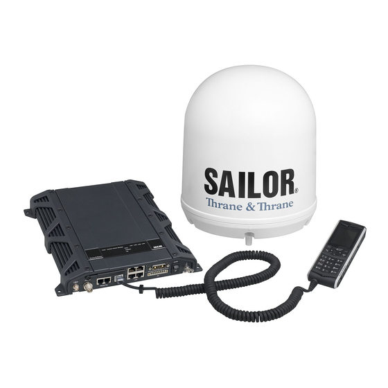
TT-3670A IP Handset & Cradle, wired SAILOR 150 FleetBroadband antenna ® The SAILOR 150 FleetBroadband system uses the TT-3050C antenna, which is a small size, maritime BGAN antenna. For information on how to install the antenna, refer to the installation manual. 98-129217-A... - Page 12 150 FleetBroadband terminal ® Overview The SAILOR 150 FleetBroadband Terminal is the controlling unit in the SAILOR 150 FleetBroadband system. It contains all user interfaces and a LED indicator and stores configuration data. Tools for setup and daily use The Thrane IP Handset can be used for displaying status and for entering the PIN code for the terminal.
- Page 13 The Thrane IP Handset communicates using Internet Protocols (IP). The handset is not strictly dedicated to the SAILOR 150 FleetBroadband system, but can also be used in a public network as a standard IP telephone. The IP handset is powered directly from the LAN interface using Power over Ethernet (PoE).
- Page 14 Chapter 1: Introduction IP cradle The IP cradle serves as a holder for the IP handset. The cradle connects to the coil cord from the handset and, using an Ethernet cable, to the terminal. You can mount the cradle on a wall or a desktop. 98-129217-A Main units...
-
Page 15: The Inmarsat Bgan System
Chapter 1: Introduction The Inmarsat BGAN system What is BGAN? The Broadband Global Area Network (BGAN) is a mobile satellite service that offers high-speed data and voice telephony. BGAN enables users to access e-mail, corporate networks and the Internet, transfer files and make telephone calls. The Inmarsat FleetBroadband service FleetBroadband is a maritime communications service offered in the BGAN system. - Page 16 Chapter 1: Introduction Overview of the BGAN FleetBroadband system A complete BGAN FleetBroadband system includes the SAILOR 150 FleetBroadband terminal with connected peripherals, a SAILOR 150 FleetBroadband antenna, the BGAN satellite, and the Satellite Access Station (SAS). The satellites are the connection between your terminal and the SAS, which is the gateway to the worldwide networks (Internet, telephone network, cellular network, etc.).
- Page 17 Short Messaging Service (SMS) Packet data service The packet data service available for the SAILOR 150 FleetBroadband offers a Standard IP (background) connection where several users can share the data connection simultaneously. This type of connection is ideal for e-mail, file transfer, and Internet and intranet access. The user pays for the amount of data sent and received.
-
Page 18: Access To Services And Interfaces
Chapter 1: Introduction Limitations SIM lock The supplier may have locked the SIM card to a specific provider. For further information, contact your supplier. Limitations in available services The services available depend on your airtime subscription. Your SIM card may not allow for all the services described in this manual. -
Page 19: Chapter 2 Getting Started
For further information on installation, refer to the installation manual for the SAILOR 150 FleetBroadband system. Connector panel The drawing below shows the connector panel of the SAILOR 150 FleetBroadband terminal. Power DC input Reset button Slot for SIM card... -
Page 20: Starting Up The Terminal
Starting up the terminal SIM card Note that the SAILOR 150 FleetBroadband terminal requires a SIM card dedicated to FleetBroadband. The terminal can only access the BGAN network when the right type of SIM card is installed. For information on how to insert the SIM card, refer to the installation manual. - Page 21 Chapter 2: Getting started Power up completed When the terminal is switched on, the Power indicator in the terminal lights green. You can now access the terminal settings, but the terminal is not ready for making calls or running data sessions until the system is registered on the BGAN network. You may have to enter a SIM PIN before the system can register.
-
Page 22: Connecting The Thrane Ip Handset
In case of power hold-up (failure on input power), PoE will be turned off completely. Starting up the Thrane IP Handset The SAILOR 150 FleetBroadband only supports connection of one IP handset, which must Note be the Thrane IP Handset. -
Page 23: Connecting A Computer
Chapter 2: Getting started Connecting a computer Before connecting to the LAN interface For the LAN interface to work without any further setup, the connected computer must be set up to obtain an IP address and a DNS server address automatically. To check this on your computer (Windows XP), do as follows: Go to Start >... -
Page 24: Entering The Sim Pin For The Terminal
Chapter 2: Getting started Entering the SIM PIN for the terminal Overview Depending on your SIM card, you may have to enter a SIM PIN to use the system. Your SIM PIN is supplied with your SIM card. You can enter the PIN using a standard phone, the IP handset or the web interface. - Page 25 Chapter 2: Getting started If you enter 10 wrong PUKs, the SIM card will no longer be functional. Contact your Airtime Provider for a new SIM card. IP handset: After having entered the user name and password for the terminal you have 3 attempts to enter the SIM PIN, before you are asked to enter the PUK (Pin Unblocking Key).
-
Page 26: Registering With The Bgan Network
Airtime Provider for a new SIM card. Registering with the BGAN network When the SIM PIN is accepted by the terminal, the SAILOR 150 FleetBroadband system automatically starts the registration procedure on the BGAN network. You can monitor the registration procedure in two ways. -
Page 27: Making The First Call
Chapter 2: Getting started Making the first call Introduction When the terminal is registered with the BGAN network you are ready to make or receive the first call. The following sections provide a short guide to making calls. For more detailed information, see Making or receiving a phone call on page 23. -
Page 28: Standard Connection To The Internet (Default)
Chapter 2: Getting started Standard connection to the Internet (default) This section only describes a Standard Internet connection with default settings on the Note terminal. For information on other scenarios, see Setting up the LAN network on page 54. By default, the terminal does not automatically connect to the Internet when you connect your computer or other equipment to the LAN interface. -
Page 29: Chapter 3 Operating The System
Operating the system In this chapter This chapter describes how to use the SAILOR 150 FleetBroadband system. It does not describe advanced configuration of interfaces. For this type of information, refer to the “Configuring...” sections for the interfaces in Chapter 4, Using the web interface. - Page 30 Chapter 3: Operating the system • Possibility of using UTC time received from the BGAN satellite. For further information, see the user manual for the IP handset. The web interface of the terminal The web interface is a built-in web server for setting up and controlling the terminal, using a connected computer with a browser.
-
Page 31: Using A Phone
Thrane IP handset. For information on the features and functions of the Thrane IP Handset, refer to the user manual for the handset. For information on how to connect to the interfaces, see the installation manual for the SAILOR 150 FleetBroadband system. Making or receiving a phone call Making a call First connect your phone to the relevant interface. - Page 32 Chapter 3: Operating the system Receiving a call To be able to receive a call, the phone must be connected to the relevant interface on the terminal. By default, any handset connected to the Phone interface or the LAN (PoE) interface will ring when the mobile number is called.
-
Page 33: Dialing Functions
Chapter 3: Operating the system Dialing functions Local numbers and special-purpose numbers There are a number of dialing functions available in the terminal. The following list shows the allocated special-purpose numbers for the terminal. Remember the “0” when you dial a local phone number. If you accidently dial a 3-digit Note number, you may get one of Inmarsat’s short dial numbers. - Page 34 Chapter 3: Operating the system Handling waiting calls The phone must have an R key to be able to use these functions. Note During a call, if a second party tries to call you, you may hear a Call Waiting indication. The Call Waiting indication is two beeps and a pause of 3 seconds, then two beeps again etc.
- Page 35 Chapter 3: Operating the system Holding a call The phone must have an R key to be able to use these functions. Note During a call, you may place the initial call on hold while another call is made. If you want to: Do as follows: Press R 2 #.
-
Page 36: Using A Computer
The terminal has two LAN connectors for connecting computers, the Thrane IP Handset or other LAN equipment. For information on how to connect to the interfaces, see the installation manual for the SAILOR 150 FleetBroadband system. Working with network user groups Two network user groups are available to the users of the terminal: The Default group: By default, all users belong to the Default network user group, which •... -
Page 37: Using The Ip Handset
You can use the Thrane IP Handset as user interface for the SAILOR 150 FleetBroadband system as well as for making calls. The IP handset has a dedicated menu for the SAILOR 150 FleetBroadband system. You find a list of the menu items available in The IP handset on page 21. -
Page 38: Chapter 4 Using The Web Interface
Chapter 4 Using the web interface In this chapter This chapter describes how to use the web interface to operate, set up and configure your SAILOR 150 FleetBroadband system. Introduction The web interface What is the web interface? The web interface is built into the terminal and is used for operating, setting up and configuring the system. - Page 39 Chapter 4: Using the web interface Proxy settings when accessing the web interface If you are connecting your computer using a LAN or WLAN interface, the Proxy server settings in your browser must be disabled before accessing the web interface. Most browsers support disabling of the Proxy server settings for one specific IP address, so you can disable Proxy server settings for the web interface only, if you wish.
-
Page 40: Accessing And Navigating The Web Interface
Chapter 4: Using the web interface Accessing and navigating the web interface Accessing the web interface To access the web interface, do as follows: Connect your computer to the terminal. 2. Start up the terminal. For details, see Getting started on page 11. 3. - Page 41 Chapter 4: Using the web interface Overview of the web interface When the web interface opens, the title bar shows the name of the product. The web interface consists of the following sections. Title bar Icon bar Contents section Status field Navigation pane...
- Page 42 Chapter 4: Using the web interface Icons in the icon bar The following icons may appear in the icon bar in the web interface: Icon Explanation A new SMS message, or information of Voice mail, has arrived. Click the icon to see new messages or information of Voice mail.
-
Page 43: Entering The Sim Pin In The Web Interface
Chapter 4: Using the web interface Entering the SIM PIN in the web interface Do you need a SIM PIN? You may not have to enter a SIM PIN to access the terminal. This depends on whether or Note not the use of a SIM PIN is enabled on your SIM card. The administrator can enable and disable the use of a SIM PIN. -
Page 44: Using The Dashboard
Chapter 4: Using the web interface Using the Dashboard Overview The Dashboard is used for control and inspection of ongoing communication and for viewing properties and status of the terminal and antenna. For information on how to start or stop your data sessions from the Dashboard, see Connecting to the Internet on page 28. - Page 45 The PROPERTIES section of the DASHBOARD shows the following information: Airtime provider. The name of your Airtime Provider. • GPS position. The GPS position of your SAILOR 150 FleetBroadband system. • In some cases, the BGAN network does not allow the position to be displayed to the Note user.
- Page 46 Chapter 4: Using the web interface Viewing information on calls and data sessions The following sections in the Dashboard show information on calls and data sessions. The counters for calls and data sessions are only intended as a guide and cannot be used Note for direct comparison with your airtime bill.
-
Page 47: Using The Phone Book
Chapter 4: Using the web interface Using the phone book General usage Overview In the phone book you can: • Look up phone numbers. • Look up short-dial numbers for easy dialing from a handset. • Modify or delete existing names and phone numbers, or add new names and phone numbers. Accessing the phone book To access the phone book, select PHONE BOOK from the left navigation pane. -
Page 48: Editing Phone Book Entries
Chapter 4: Using the web interface The phone book shows all entries with entry number, name and phone number. Empty place holders are also included. To sort the phone book, click the title of the column you wish to sort by. For example, to sort by the names in the phone book alphabetically, click on Name in the top row of the phone book. - Page 49 Chapter 4: Using the web interface Viewing and editing the mobile number The mobile number is the phone number to use when making a call to the terminal. To view the mobile number To view the mobile number of the terminal, select PHONE BOOK > Mobile numbers from the left navigation pane.
-
Page 50: Using The Call Log
Chapter 4: Using the web interface Using the Call log Information on total usage To enter the CALLS page select CALLS from the left navigation pane. This page contains information on usage for circuit-switched connections. 98-129217-A Using the Call log... -
Page 51: Exporting The Call Log
Chapter 4: Using the web interface Exporting the call log You can export the call log file and save it on your computer for archiving, surveillance or other tracking purposes. The call log holds information on all calls and data sessions since the call log was last cleared. For information on how to view the lists of calls and data sessions, see the next section. -
Page 52: Handling Sms Messages
Chapter 4: Using the web interface Handling SMS messages Sending an SMS message If the terminal is not online when you attempt to send a message, the message is Important moved to the Outbox instead of the Sent folder. Messages in the Outbox are not automatically sent when the terminal goes online. -
Page 53: Options For Messages In The Outbox
Chapter 4: Using the web interface 5. Select whether or not you want Delivery notification for this SMS message. If you click Yes, the Status column in the Sent folder will show the status of your message when it has been sent. You can set up delivery notification generally for all SMS messages. -
Page 54: Receiving A Message
Chapter 4: Using the web interface Sending an SMS message to the terminal You can send an SMS message to the terminal e.g. from a mobile phone, using the mobile number for the terminal. Dial + <Mobile number> The first part of the mobile number is always 870, which is the “country code” for the BGAN system. If the mobile number is listed in the web interface, you can look it up as follows: Select PHONE BOOK >... -
Page 55: Options For New Sms Messages
Chapter 4: Using the web interface Options for new SMS messages To see new messages, click MESSAGES from the left navigation pane. Besides viewing the new messages, you have a number of options for what to do with each message: Click Archive to move it to your Inbox containing read messages. -
Page 56: Configuring Message Settings
Chapter 4: Using the web interface Configuring message settings Setting up the default message options You can set up general options for your outgoing messages. These settings apply by default to all your outgoing messages. Note, however, that you can change the Delivery notification setting for an individual message. - Page 57 Chapter 4: Using the web interface Viewing or changing SMS service center number The SMS service center number identifies the SMS service center used when sending and receiving SMS messages. The SMS service center number is stored on the SIM card. •...
-
Page 58: Setting Up The Interfaces
Chapter 4: Using the web interface Setting up the interfaces The SETTINGS page (Antenna properties) The SETTINGS page shows properties of the connected antenna. To access the SETTINGS page, select SETTINGS from the left navigation pane. 98-129217-A Setting up the interfaces... -
Page 59: Configuring The Lan Interface
Chapter 4: Using the web interface Configuring the LAN interface Overview The SAILOR 150 FleetBroadband terminal has 2 LAN connectors with PoE (Power over Ethernet). Some of the LAN parameters are set up in the network management pages, which require administrator password. - Page 60 Chapter 4: Using the web interface To change the local IP address, do as follows: From the left navigation pane, select SETTINGS > LAN. 2. At DHCP status, select Enabled (recommended for most purposes), or Disabled. • If you select Enabled, the terminal assigns dynamic IP addresses to devices connected to the terminal.
- Page 61 Chapter 4: Using the web interface Port forwarding Port forwarding enables you to set up a server connected to the terminal while the terminal is in Router mode. Without port forwarding it would not be possible to contact the server from the Internet.
- Page 62 Chapter 4: Using the web interface You can now access the mail server from the Internet, using the external IP address of the terminal. If you do not know the IP address, you can look it up in the DASHBOARD of the web interface under ONGOING DATA SESSIONS.
- Page 63 Chapter 4: Using the web interface Setting up the Default network user group The Default network user group provides a shared Standard connection to the Internet using the built-in router functionality of the terminal. If you want to apply other settings to the Default network user group, do as follows: Select SETTINGS >...
- Page 64 Chapter 4: Using the web interface • Router mode means the connection will be shared with other users, and the NAT module of the terminal will make the necessary address translations. Use this mode if one or more computers are connected using the LAN interface, and the terminal should act as a router. •...
- Page 65 Chapter 4: Using the web interface Setting up a Bridge mode connection To set up a Bridge mode connection, do as follows: Select SETTINGS > LAN > Network user groups. 2. When you are prompted, enter the administrator user name and password. The default user name is admin and the default password is 1234.
- Page 66 Chapter 4: Using the web interface 3. Click Edit next to Group 0. If you want, you can change the name of the group to something more meaningful, e.g. to “Bridge mode”. 4. At Status, select Enabled. 5. Select Dynamic IP address. This is the IP address used externally on the satellite network.
- Page 67 Chapter 4: Using the web interface Select the source of the APN (Access Point Name). There are four options for setting the APN. Unless you have special requirements, it is recommended to use the SIM default, or to set the common APN to SIM default, and then select Common here.
- Page 68 Chapter 4: Using the web interface For details on how to set up the Default group, see Setting up the Default network user group on page 55. 12. Select SETTINGS > LAN > Network classification. The network classification table is used to define which network devices, IP addresses and/or LAN ports are associated with which network user groups.
- Page 69 Chapter 4: Using the web interface • Type in the MAC address in the MAC address field at the top of the page. An asterisk indicates a “wild card”, which means any MAC address is accepted. IP address: If you want a specific IP address to belong to Group 0, type in the IP address in the IP address field.
- Page 70 Chapter 4: Using the web interface Viewing network devices All network devices that are or have been connected to the terminal are listed in the Network devices page. To view the list of network devices, select SETTINGS > LAN > Network devices. If you are prompted, enter the administrator user name and password.
- Page 71 Chapter 4: Using the web interface Definitions for network terms APN (Access Point Name) APNs are provided from the Airtime Provider. They may also be defined on the SIM card The APN is used by the network user to establish a connection to the required external network. This means that the terminal must know the APN in order to be able to connect to the external network.
- Page 72 On the equipment connected to the SAILOR 150 FleetBroadband terminal you must enter a few settings for your PPPoE connection. For example you need to set up which service to use and possibly a user name and password.
-
Page 73: Configuring The Phone Interface
Chapter 4: Using the web interface Configuring the Phone interface To enable/disable incoming calls on the Phone interface do as follows: Select SETTINGS > Phone from the left navigation pane. 2. Select Standard if you want to be able to receive calls through the Phone interface. Only calls with Standard call type are accepted. - Page 74 Chapter 4: Using the web interface How to use the common APN When you configure the APN for your individual network user group, select Common to use the setting from this page. If you are using the same APN for both network user groups, it is easier to define it once under Common, and then simply select Common for the relevant network user groups.
-
Page 75: Setting Up Call Services
Chapter 4: Using the web interface Setting up call services Overview The setup of call services is also common for all interfaces. The terminal must be registered on the BGAN network before you can set up the call Note services in the web interface. In the web interface you can set up the following supplementary services: •... - Page 76 Chapter 4: Using the web interface Call forwarding You can set up the terminal to automatically forward incoming calls to another phone number. This information is saved in the BGAN network so it is available when the call cannot be put through and must be forwarded.
- Page 77 Chapter 4: Using the web interface Call barring Do as follows to bar incoming and/or outgoing calls to and from the terminal: Select SETTINGS > Common > Call barring from the left navigation pane. 2. Click OK next to Read current settings, to make sure the page is updated. 3.
- Page 78 Chapter 4: Using the web interface Call waiting You can set up whether or not you want to receive notification of waiting calls while you are making a call or transmitting data. Do as follows: Select SETTINGS > Common > Call waiting from the left navigation pane. 2.
- Page 79 Chapter 4: Using the web interface Line identification You can set up the terminal to show your number when you are making a call. Do as follows: Select SETTINGS > Common > Line identification from the left navigation pane. 2. Select Show my number and click Apply. 98-129217-A Setting up the interfaces...
- Page 80 Chapter 4: Using the web interface Closed user group Your subscription may include one or more closed user groups. A closed user group is a group of users permitted to make calls to each other but not to users outside the group. To define the settings for these user groups, do as follows: Select SETTINGS >...
- Page 81 Chapter 4: Using the web interface Setting up the connection to the Thrane IP Handset Overview By default, the handset is automatically connected at startup, so no configuration is necessary! The terminal is set up to assign the user name 0501 and the password 0501 to the Thrane IP Handset when it is connected.
- Page 82 Chapter 4: Using the web interface The page is updated as shown. To be able to access the terminal with a Thrane IP Handset again you must click New and enter the password. Note that the Thrane IP Handset only supports numbers (no letters) in the password.
- Page 83 Chapter 4: Using the web interface Enabling/Disabling incoming calls to a connected Thrane IP Handset To enable or disable incoming calls on the LAN (PoE) interface, do as follows: Select SETTINGS > IP handsets > Call settings. 2. Select Standard if you want to be able to receive calls through the LAN interface. Only calls with Standard call type are accepted.
- Page 84 Chapter 4: Using the web interface Setting up the IP handset compatibility If you are connecting your Thrane IP Handset to the terminal through a separate router with NAT, you must use an IP handset with software version 1.8 or newer and set up the handset compatibility in the web interface of the terminal as described below.
- Page 85 Chapter 4: Using the web interface Configuring the discrete I/O interface I/O pins and their functions The I/O interface on the terminal has 5 configurable I/O pins. You can set up the function of each pin in the web interface. The default functions of the I/O pins are as follows: Pin 1: Ringer output.
- Page 86 Chapter 4: Using the web interface Configuring the I/O interface To configure the I/O pins, do as follows: Select SETTINGS > Discrete I/O. 2. For each pin you want to use, select Enabled. 3. For each pin, select the function of the pin. Refer to the previous section, I/O pins and their functions on page 77.
-
Page 87: Uploading Software
Chapter 4: Using the web interface Uploading software Introduction The next pages describe how to upload software from your computer to the terminal and how to download the latest software version from the Internet to your computer. You can upload software from your computer to the terminal without entering the PIN. However, if your SIM card requires a PIN and the PIN is not entered, you must enter the Administration user name and password. -
Page 88: Uploading Software From Your Computer
Chapter 4: Using the web interface Uploading software from your computer To upload software from your computer to the terminal, do as follows: Download the new software as described in the next section, or acquire the software from Thrane & Thrane A/S and save it on your computer. 2. -
Page 89: Downloading Software From The Internet
Chapter 4: Using the web interface Downloading software from the Internet The terminal uses your BGAN airtime subscription to download the new software Important from the Internet. Note that it can take several minutes to download the software. If you don’t want to use airtime you can acquire the software from Thrane & Thrane, save it on your computer and then connect the computer to the terminal. -
Page 90: Selecting The Preferred Bgan Satellite
Select SETTINGS > Satellite selection from the left navigation pane. 2. Select the satellite you prefer to use. If you select Auto (the default setting) the SAILOR 150 FleetBroadband system automatically uses the most appropriate satellite. If you have any ongoing calls or data sessions, they will be terminated when... -
Page 91: Selecting The Language
The SAILOR FleetBroadband terminates all ongoing connections and deregisters from the current satellite before registering on the new satellite. If you have selected one of the satellites, your SAILOR 150 FleetBroadband system will Note only try to register on the selected satellite. This means that if the antenna is outside the coverage area for that satellite, the SAILOR 150 FleetBroadband system will not be able to register with the BGAN network. -
Page 92: Administration
Chapter 4: Using the web interface Administration Accessing the administration settings Logging on The Administration settings require an Administration user name and password. To log on as administrator, do as follows: Select ADMINISTRATION from the left navigation pane. 2. Enter the Administration user name and password. The default user name is admin and the default password is 1234. - Page 93 Chapter 4: Using the web interface Resetting the administrator password If you have forgotten the administrator password, do as follows: Contact your supplier for a reset code. Please report the serial number and IMEI number of the terminal. You can find the serial number and IMEI number in the Dashboard. 2.
- Page 94 Chapter 4: Using the web interface Changing the administrator password To change the administrator password, do as follows: After entering the administrator user name and password in the ADMINISTRATION page, locate the section Change administrator logon. 2. Type in the existing user name. 3.
- Page 95 Chapter 4: Using the web interface Saving a configuration to a file If you need to reuse a configuration in another terminal of the same type, you can save your current configuration to a file, which can then be loaded into the other terminal. To save your current configuration to a file, do as follows: In the ADMINISTRATION page, under Configuration, click Save.
- Page 96 Chapter 4: Using the web interface Call charges If you know the tariff for your subscribed services, you can enter these tariffs in the web interface and automatically calculate the charges for your calls and data sessions. To enter the call tariffs, do as follows: From the left navigation pane, select ADMINISTRATION >...
- Page 97 Chapter 4: Using the web interface Setting up the use of SIM PIN in the terminal Enabling or disabling the use of a SIM PIN To enable or disable the use of a PIN to access the terminal, do as follows: Select ADMINISTRATION >...
- Page 98 Chapter 4: Using the web interface Changing the SIM PIN To change the PIN used to access the terminal, do as follows: Select ADMINISTRATION > SIM PIN. 2. Under CHANGE PIN type in the Old PIN. 3. Type in the New PIN and retype it on the next line. 4.
-
Page 99: Setting Up User Permissions
Chapter 4: Using the web interface Setting up user permissions You can allow or deny users that are not administrators access to certain functions and make these pages read-only. This is useful if you want to protect the system against unintended changes. - Page 100 This setting does not take effect until the terminal is restarted. Note AT commands are low-level commands used to control modems, in this case the SAILOR 150 FleetBroadband terminal. They are typically used during service and maintenance or when troubleshooting the terminal. 4. Click Apply.
-
Page 101: Help Desk And Diagnostic Report
Chapter 4: Using the web interface Help desk and diagnostic report Accessing the Help desk If you need help with airtime-related issues you may call the Help desk. By default, the Help desk is the phone number for your Airtime Provider, if it is available on the SIM card. To access the Help desk, select HELP DESK from the left navigation pane. -
Page 102: Event Logging And Self Test
To view the Event log, select HELPDESK > Event log from the left navigation pane. Self test The Self test performs system test on the SAILOR 150 FleetBroadband system, similar to the tests that are performed during the Power On Self Test (POST). -
Page 103: Site Map
Chapter 4: Using the web interface Extended status To view updated information on the Extended status page, click Refresh. The Extended Status page shows the following information: • The antenna type (must always be TT-3050C). • The status of the connection to the air interface (IAI-2). This field should normally show “Registered”, unless the system is still in the startup process. -
Page 104: Chapter 5 Troubleshooting
Chapter 5 Troubleshooting In this chapter This chapter gives guidelines for troubleshooting and provides an overview of the different means of status signaling, It also lists available spare parts and accessories. Getting support Overview If this manual does not provide the remedies to solve your problem, you may want to contact your Airtime Provider or your local distributor. -
Page 105: Uploading Software
Chapter 5: Troubleshooting Uploading software Viewing software version status To view the version of the embedded software in the terminal, do as follows: Connect a computer. 2. Enter the web interface and see the Software version field in the Dashboard. Uploading software using the web interface You can upload software from the web interface. -
Page 106: Part Numbers
Chapter 5: Troubleshooting Part numbers System units TT-3744A SAILOR 150 FleetBroadband system ® Item Part number SAILOR 150 FleetBroadband antenna 403050C SAILOR 150 FleetBroadband terminal 403739A TT-3670A Thrane IP Handset & Cradle, wired Item Part number Thrane IP Handset, wired... -
Page 107: Troubleshooting Guide
Chapter 5: Troubleshooting Troubleshooting guide The below table provides information on some of the problems that might occur, including possible causes and remedies to solve the problems. Problem Possible Cause Remedy No signal or weak The view to the satellite Make sure the antenna has a clear view in signal from the is blocked. - Page 108 Chapter 5: Troubleshooting Problem Possible Cause Remedy For Microsoft Internet Explorer, select Tools The web interface The browser is > Internet Options > Connections > LAN cannot be accessed. configured to use a Settings and uncheck Use a proxy server proxy server.
- Page 109 Chapter 5: Troubleshooting Problem Possible Cause Remedy An IP handset The cable is not properly Connect the cable. connection cannot connected. be established. There is no power (PoE) Check that the input voltage is within the in the LAN interface. The specified range reason may be that there (10.5 - 32 V DC;...
-
Page 110: Status Signaling
Chapter 5: Troubleshooting Status signaling Overview There are many ways of troubleshooting if an error occurs. The terminal has different means of status signaling, to help you find the cause of a problem: Indicator. • • Event messages. • Event log. Indicator, event messages and logs are described in the following sections. - Page 111 Chapter 5: Troubleshooting List of events The following list explains the events that may show in the web interface of the terminal. Event Text Explanation Remedy 00100 to Important system data is Do not use the terminal. System data 00199 damaged Contact your distributor.
- Page 112 10 minutes to obtain GPS fix. 01400 to Make sure the Satellite 01409 SAILOR 150 FleetBroadband no SAILOR 150 FleetBroadband signal lost longer receives a signal from has a clear view to the satellite. the satellite. 01500 to No SIM card is detected in the Insert SIM card.
- Page 113 Chapter 5: Troubleshooting Event Text Explanation Remedy 01700 to Restart the terminal. Registration 01709 SAILOR 150 FleetBroadband for voice If the problem persists, contact has not yet been allowed to failed your Airtime Provider. register for voice services (Circuit-Switched). 01800 to Restart the terminal.
- Page 114 Chapter 5: Troubleshooting Event Text Explanation Remedy 03600 to The Phone interface fails to 2-wire 03609 operate, for one of the operational following reasons: failure Ground shorted. Check the wires. 2. Power overload. 2. Wait until the event is cleared; then try again. 3.
- Page 115 The antenna hardware version Check that both the antenna Firmware image is not supported by the and the terminal are of the type doesn't support terminal. SAILOR 150 FleetBroadband. antenna hardware Contact your distributor if the problem persists. 98-129217-A Status signaling...
- Page 116 Chapter 5: Troubleshooting Event Text Explanation Remedy 08034 New firmware was successfully Reboot the terminal. Contact Antenna failed uploaded to the antenna but your distributor if the problem to exit Flash the antenna failed to start persists. Manager. Power normally with the new cycle needed firmware.
- Page 117 Chapter 5: Troubleshooting Event Text Explanation Remedy 0804B You are not using the right Only use the antenna(s) Illegal combination of antenna and intended for use with your combination of terminal. terminal. antenna and terminal 0804C The terminal is set up to use a Enter the web interface and The chosen select SETTINGS >...
-
Page 118: Logging Of Events
Chapter 5: Troubleshooting Logging of events Diagnostic report When contacting your distributor for support, please include a diagnostic report. The diagnostic report contains information relevant for the service personnel during troubleshooting. To generate the diagnostic report, access the web interface and select HELPDESK. Then click Generate report. -
Page 119: Reset Button
Chapter 5: Troubleshooting Reset button How to access the Reset button The terminal has a Reset button placed next to the SIM slot behind the SIM cover. The functions of this button is described in the next section. To press the Reset button, use a pointed device. Function of the Reset button The Reset button on the terminal has the following functions: Action... -
Page 120: Chapter 6 Conformity
Chapter 6 Conformity CE (R&TTE) The SAILOR 150 FleetBroadband is in the process of being CE certified (R&TTE directive). The “Declaration of Conformity with R&TTE Directive” will be enclosed in copy on the next page when ready. 98-129217-A... - Page 121 Chapter 6: Conformity REPLACE THIS PAGE IN THE PDF FILE WITH THE DECLARATION OF CONFORMITY FOR SAILOR 150 FleetBroadband. 98-129217-A...
-
Page 122: Glossary
Glossary Glossary Access Point Name. The Access Point Name is used by the terminal operator to establish the connection to the required destination network. BGAN Broadband Global Area Network. A satellite network based on geostationary satellites, delivering data rates of up to 492 kbps to virtually any part of the earth, with full UMTS (3G) compatibility. - Page 123 Glossary satellite resources. IMEI International Mobile Equipment Identity. A unique number identifying your terminal IMSO International Maritime Satellite Organisation. An intergovernmental body established to ensure that Inmarsat continues to meet its public service obligations, including obligations relating to the GMDSS. Internet Protocol Local Area Network Light Emitting Diode...
- Page 124 Glossary Subscriber Identity Module.The SIM provides secure storing of the key identifying a mobile phone service subscriber but also subscription information, preferences and storage of text messages. Session Initiation Protocol. An application-layer control (signaling) protocol for creating, modifying, and terminating sessions with one or more participants. Used e.g. for Internet telephony.
-
Page 125: Index
Index Index Numerics calls barring 2-wire interface closed user group enabling or disabling incoming calls enabling or disabling incoming local numbers forwarding holding line identification local making or receiving access to services and interfaces missed, received, outgoing administration settings redial analog phone to the terminal local numbers... - Page 126 Index IP handset BGAN features Ethernet interface connecting setting up description events entering PIN list of active local numbers exporting configuration power supply extended status starting up user manual ip handset setting up features overview forwarding calls connecting a computer setting up interface GPS position limitations in services...
- Page 127 Index satellite selecting phone view current local call view selected making calls sent messages phone book resending, forwarding or deleting adding number viewing status deleting all entries serial number deleting an entry services modifying an entry limitations Phone interface supported by BGAN enabling or disabling incoming calls services and interfaces local numbers...
- Page 128 Index transferring a call troubleshooting guide typography used in this manual uploading software usage counter clearing user interfaces version of software voice mail number viewing waiting calls web interface accessing browser settings definition navigating site map 98-129217-A...
Need help?
Do you have a question about the SAILOR 150 and is the answer not in the manual?
Questions and answers