Table of Contents
Advertisement
Quick Links
Advertisement
Table of Contents
Troubleshooting

Related Manuals for Thrane&Thrane TT-3720A EXPLORER 700


Summary of Contents for Thrane&Thrane TT-3720A EXPLORER 700
- Page 1 EXPLORER 700 USER MANUAL Thrane & Thrane A/S • info@thrane.com • www.thrane.com...
- Page 2 TT-3720A EXPLORER™ 700 Document number: 98-122988-B Release date: 19 June 2006 Information in this document is subject to change without notice and does not represent a commitment on the part of Thrane & Thrane A/S. Copyright © 2006 Thrane & Thrane A/S. All rights reserved. Trademark Acknowledgements •...
-
Page 3: Safety Summary
Safety Summary The following general safety precautions must be observed during all phases of operation, service and repair of this equipment. Failure to comply with these precautions or with specific warnings elsewhere in this manual violates safety standards of design, manufacture and intended use of the equipment. -
Page 4: Antenna Safety Instructions
Antenna Safety Instructions FCC Radiation Exposure statement Transceiver Unit (when separated from the Antenna Unit): This equipment complies with FCC radiation exposure limits for an uncontrolled environment. This equipment should be installed and operated at a distance greater than 20 centimeters (8 inches) between the Transceiver Unit, yourself or any bystander to comply with the Radiation Exposure Requirements. -
Page 5: About The Manual
About the Manual About the Manual Intended Readers This manual is a user manual for the EXPLORER™ 700. The readers of the manual include anyone who is using or intends to use the EXPLORER™ 700. No specific skills are required to operate the EXPLORER™ 700. However, it is important that you observe all safety requirements listed in the beginning of this manual, and operate the EXPLORER™... -
Page 6: Table Of Contents
Table of Contents Safety Summary ....................iii Antenna Safety Instructions .................. iv About the Manual ....................v Chapter 1 Introduction Welcome ........................1 In this chapter ....................... 2 The BGAN system ....................3 The BGAN services ....................5 Features and interfaces of the EXPLORER™ 700 ............6 Your EXPLORER™... - Page 7 Table of Contents Connect menu ..................... 40 Calls menu ......................41 Settings menu ..................... 42 Properties menu ....................45 Help desk ......................47 Dynamic information in the display ..............48 What’s next? ......................49 Chapter 4 Using the interfaces In this chapter ....................
- Page 8 Table of Contents Additional interfaces ..................79 Using the EXPLORER™ 700 antenna ..............79 Using a solar panel .....................80 Using the I/O interface ..................81 Using the EXPLORER™ Bluetooth Handset charger ..........82 What’s next? ...................... 82 Chapter 5 Using the web interface In this chapter ....................
- Page 9 Table of Contents Power up behavior .....................102 Setting the display backlight and contrast ............103 Turning audio indicators on or off ..............103 Enabling activation of stealth mode ..............104 Setting up the interfaces .................105 Enabling/disabling interfaces ................105 Description of data settings ................106 Configuring the USB interface ................108 Configuring the LAN interface ................
- Page 10 Table of Contents Alarm messages ....................149 Log files ......................155 Appendix A Technical specifications In this appendix ....................156 General specifications ..................156 Battery ....................... 157 Power input ......................158 SIM interface ......................158 Phone/Fax interface, 2-port ................159 ISDN interface, 2-port ..................160 LAN interface, 2-port ...................161 USB interface .....................
-
Page 11: Chapter 1 Introduction
Chapter 1 Introduction Welcome Congratulations on the purchase of your EXPLORER™ 700! The EXPLORER™ 700 is a broadband mobile terminal with a detachable antenna, providing high- speed data and voice communication via satellite through the Broadband Global Area Network (BGAN). Just plug in a phone, fax, laptop or PDA, or use the Bluetooth®... -
Page 12: In This Chapter
Chapter 1: Introduction Applications include: • Internet browsing • E-mail • Phone and fax services • Large file transfers • Video conferencing and Streaming • VPN (Virtual Private Network) access to corporate servers In this chapter This chapter gives an overview of the BGAN system and services, and introduces the EXPLORER™... -
Page 13: The Bgan System
Chapter 1: Introduction The BGAN system What is BGAN? The Broadband Global Area Network (BGAN) is a mobile satellite service that offers high-speed data up to 492 kbps and voice telephony. BGAN enables users to access e-mail, corporate networks and the Internet, transfer files and make telephone calls. Coverage The Inmarsat®... - Page 14 Chapter 1: Introduction Overview of the BGAN system A complete BGAN system includes the EXPLORER™ 700 with connected peripherals, the BGAN satellite, and the Satellite Access Station (SAS). The satellites are the connection between your EXPLORER™ 700 and the SAS, which is the gateway to the worldwide networks (Internet, telephone network, cellular network, etc.).
-
Page 15: The Bgan Services
Chapter 1: Introduction The BGAN services Supported services The services currently supported by BGAN comprise: • A Packet Switched connection to the Internet • A Circuit Switched (Dialed) connection for voice, fax or data • Short Messaging Service (SMS) Packet data service The BGAN network supports different classes of data connection to the Internet. -
Page 16: Features And Interfaces Of The Explorer™ 700
Chapter 1: Introduction Features and interfaces of the EXPLORER™ 700 Features Simultaneous voice and data communication over BGAN Full duplex, single or multi-user, up to 492 kbps Support for streaming IP at 32, 64, 128, 256 kbps Seamless global coverage Standard LAN, WLAN, USB, ISDN, Bluetooth and Phone/Fax ports Integral DHCP/NAT wireless router Built-in web interface allowing you to manage your phone book, messages and calls, and... - Page 17 Chapter 1: Introduction Overview of interfaces The EXPLORER™ 700 provides a number of interfaces for connection of various types of computers, fax devices and phones. Using the interfaces on page 50 describes how to use each of the available interfaces. Minimizing power consumption The EXPLORER™...
-
Page 18: Your Explorer™ 700 Terminal
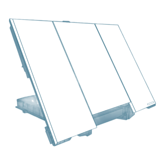
Chapter 1: Introduction Your EXPLORER™ 700 terminal Overview The EXPLORER™ 700 is a compact unit comprising a transceiver with a detachable antenna, compass, display and keypad, all in one unit. Transport Lock BGAN Antenna Compass Display and ™ Keypad EXPLORER Bluetooth Handset Connector Panel Battery... - Page 19 Chapter 1: Introduction Light indicators The EXPLORER™ 700 has two light indicators next to the display: a green power indicator and a red message indicator. Green Power indicator The function of the green Power indicator to the left of the display is as follows: Behavior of green indicator Meaning Short flash every 2 seconds...
- Page 20 Chapter 1: Introduction User interfaces The keypad and display are used for pointing the antenna, for displaying status and for changing simple parameters. To obtain full access to all features and for ease-of-use, you should use a computer (a PC, Laptop or similar) and one of the following: •...
-
Page 21: Matrix Of Services And Communication Interfaces
Chapter 1: Introduction showing battery status etc. Using the web interface, you can view the properties of the EXPLORER™ 700 and upload software without inserting a SIM card. Upload of software, however, requires an Administrator user name and password. Matrix of services and communication interfaces The following table shows which services can be accessed from which interfaces, and which types of equipment can be used. -
Page 22: Chapter 2 Getting Started
Chapter 2 Getting started In this chapter This chapter describes: • what is included in the delivery, • how to insert and remove the battery and SIM card, and • how to start up the EXPLORER™ 700 and make the first call or data session. Unpacking and assembling Unpacking Unpack the EXPLORER™... - Page 23 Chapter 2: Getting started Opening the transport latch The EXPLORER™ 700 has a transport latch, securing the transceiver and antenna during transport. Open the latch as shown. 2. You can now flip up the antenna module and access the keypad and connectors on the EXPLORER™...
- Page 24 Chapter 2: Getting started Detaching the antenna You have two options for using the EXPLORER™ 700 antenna: • Attached. You can go through the pointing process with the antenna and transceiver attached as one unit. This means you have to move the entire terminal in order to point the antenna towards the BGAN satellite.
- Page 25 Chapter 2: Getting started Inserting the SIM card The EXPLORER™ 700 is delivered with the battery separated from the terminal. If the battery is already inserted, remove it as described in Removing the battery on page 17. There are two SIM slots in the EXPLORER™ 700, marked USIM #1 and USIM #2. USIM #2 is reserved for future use.
- Page 26 Chapter 2: Getting started Inserting the battery Do as follows: Insert the battery. Make sure the battery is positioned correctly as shown. 2. Press gently until it locks. Note Before using the terminal the first time: To ensure accurate information on the battery capacity you should fully charge, then fully discharge the battery (until the EXPLORER™...
- Page 27 Chapter 2: Getting started Removing the battery To remove the battery, do as follows: If the transceiver and antenna are attached, open the transport latch and flip up the antenna module. Then gently lift the transceiver out of the antenna frame. 2.
- Page 28 Chapter 2: Getting started Removing the SIM card To remove the SIM card, first remove the battery as described in Removing the battery on page 17. Note When the SIM card is removed, you cannot use the display menu system nor make calls or start data sessions.
-
Page 29: Connecting Cables
Chapter 2: Getting started Connecting cables After inserting SIM card and battery, connect all relevant cables. Important If you are using the transceiver with the antenna attached, connect the cables before making the final adjustment of the antenna position. Otherwise you may accidently move the antenna when you connect the cables. - Page 30 Chapter 2: Getting started Before connecting to power You can connect to external power or use the battery delivered with your EXPLORER™ 700. Refer to Power input on page 158 for specifications and pin-out for the DC Power input. If you are connecting to a 100-240 V AC electrical outlet, use the AC/DC adapter included with your EXPLORER™...
-
Page 31: Powering The Explorer™ 700
Chapter 2: Getting started Powering the EXPLORER™ 700 Automatic power up The default behavior of the EXPLORER™ 700 is to power up automatically when you connect the power cable. If you wish, you can change this power up mode, so that the EXPLORER™ 700 is only powered if the Power button is pressed. -
Page 32: Options For The Start-Up Procedure
Chapter 2: Getting started Options for the start-up procedure Overview of the start-up options You have different options for the start-up procedure. Each of these options are briefly described in this section. For information on how to enter PIN and point the antenna, see the subsequent sections. The following drawing shows the options available after power on. - Page 33 Chapter 2: Getting started “Full” procedure (1) After power on, enter the PIN and then point the antenna. In this mode you have full access to the EXPLORER™ 700, that is you can use the menu system and communicate on the BGAN network. The display will show READY when the menu system is not activated.
-
Page 34: Entering The Sim Pin
Chapter 2: Getting started Entering the SIM PIN Overview You have to enter a PIN to use the EXPLORER™ 700, unless the use of PINs is disabled e.g. from the BGAN LaunchPad. The first time you are asked for a PIN, you can choose to cancel (press C). If you cancel, you are asked again after pointing is completed. -
Page 35: Pointing The Antenna
Chapter 2: Getting started Pointing the antenna The importance of pointing In order to obtain the best possible signal at the lowest possible cost, it is important that the EXPLORER™ 700 antenna is pointed correctly towards the satellite. The antenna must have a clear line of sight to the satellite without any obstacles blocking the signal, and the pointing direction of the antenna should be as accurate as possible. - Page 36 Chapter 2: Getting started Required signal strength As a rule of thumb, the signal strength should typically be 45 dBHz or more for the EXPLORER™ 700 to be able to establish a call or data session. However, the required signal strength can vary depending on a number of factors, such as weather conditions and location.
- Page 37 Chapter 2: Getting started Pointing the antenna towards the satellite You can use the EXPLORER™ 700 with the antenna attached to the transceiver, or you can detach the antenna from the transceiver and use it as a separate antenna unit. For further information, see Using the EXPLORER™...
- Page 38 Chapter 2: Getting started 4. When you have the highest signal strength you can obtain, press OK on the keypad. The EXPLORER™ 700 now tries to establish a connection to the BGAN network. The display shows the progress as follows: •...
-
Page 39: Making The First Call
Chapter 2: Getting started Making the first call Introduction After connecting cables, entering the PIN and pointing the antenna, you are ready to make or receive the first call. The following sections provide a short guide to making calls. For more detailed information, see Making or receiving a phone call with the EXPLORER™... - Page 40 Chapter 2: Getting started Making a call from one EXPLORER™ 700 to another EXPLORER™ 700 To make a call from one EXPLORER™ 700 to another EXPLORER™ 700, dial 00 870 <Mobile subscriber number>. Receiving a call To be able to receive a call, the phone must be connected to the correct interface of the EXPLORER™...
-
Page 41: Making The First Data Connection (Lan)
Chapter 2: Getting started Making the first data connection (LAN) Before connecting to the LAN interface For the LAN (Local Area Network) interface to work without any further setup, the computer must be set up to obtain an IP address and a DNS server address automatically. To check these settings on your computer, do as follows (For Windows®... -
Page 42: What's Next
Chapter 2: Getting started Connecting to the LAN interface Do as follows: Connect the LAN cable to the network interface of your computer. A suitable cable is provided with your EXPLORER™ 700. 2. Connect the other end of the cable to one of the LAN connectors on the EXPLORER™... -
Page 43: Chapter 3 Using The Display And Keypad
Chapter 3 Using the display and keypad In this chapter This chapter describes how to use the built-in display menu system of the EXPLORER™ 700. It contains an overview of the entire menu system followed by a description of each menu. It also explains the symbols and messages that may appear in the display, and describes how to navigate using the keypad. - Page 44 Chapter 3: Using the display and keypad HELP DESK • shows the phone number to the Airtime Provider, if available. For information on how to navigate in the menu system, see Navigating the display and keypad on page 37. Menu drawing The below drawing shows an overview of the menus in the display menu system of the EXPLORER™...
-
Page 45: Display During Start-Up
Chapter 3: Using the display and keypad Display during start-up Start-up sequence There are different options for the start-up procedure. The complete startup procedure is described in Chapter 2, Getting started. This section only describes the behavior of the display during normal startup. After power on you are asked for a PIN. -
Page 46: Display Symbols
Chapter 3: Using the display and keypad Display symbols Apart from the menu text, the display can show various symbols. Below is a list of the possible symbols with an explanation to each symbol. Symbol Explanation The battery charge level. When the level is too low (below 10%) the icon flashes. -
Page 47: Navigating The Display And Keypad
Chapter 3: Using the display and keypad Navigating the display and keypad Navigating with the keypad The PIN must be entered before you can access the menu system. Note In low temperatures the display may respond slowly when a key is pressed. At temperatures close to -25°C/-13°F the display may even turn black for a moment, e.g. -
Page 48: The Menus
Chapter 3: Using the display and keypad Display text When you have not entered the menu system, the Main screen shows the currently most important information. Refer to Dynamic information in the display on page 48. CANCEL in the left side of the display means: Press C to cancel the current operation. OK in the right side of the display means: Press OK to accept the current operation. -
Page 49: Messages Menu
Chapter 3: Using the display and keypad Messages menu Viewing the list of messages To see the list of SMS messages, enter the menu system and select MESSAGES. Each message is listed with the name (if known) or the number of the sender. An unopened folder indicates an unread message and an opened folder indicates a read... -
Page 50: Connect Menu
Chapter 3: Using the display and keypad Connect menu Streaming Profiles Using the web interface you can define a number of Profiles for data transmission. The Streaming Profiles defined and selected for the LAN interface appear in the CONNECT menu, and can be started and stopped using the keypad. -
Page 51: Calls Menu
Chapter 3: Using the display and keypad Calls menu To see a list of calls and data sessions, do as follows: Select CALLS. 2. Select one of the following: • MISSED: to see a list of incoming calls that were not answered. •... -
Page 52: Settings Menu
Chapter 3: Using the display and keypad Settings menu Point now Important This function will interrupt any ongoing calls or sessions! If you need to repoint the antenna, select SETTINGS > POINT NOW. This will bring you to the Pointing screen, described in Pointing the antenna towards the satellite on page 27. - Page 53 Chapter 3: Using the display and keypad Turning audio indicators on or off The EXPLORER™ 700 has audio indicators to indicate an event. You can turn each of these audio indicators on or off. Select SETTINGS > AUDIO INDICATOR. 2. Select one of the following: •...
- Page 54 Chapter 3: Using the display and keypad Setting the power up mode By default, the EXPLORER™ 700 starts up automatically when you apply external power. You can change this mode, so that you always have to press the Power button to switch on the EXPLORER™...
-
Page 55: Properties Menu
Chapter 3: Using the display and keypad Properties menu Viewing known Bluetooth devices You can view a list of the Bluetooth devices that are paired with the EXPLORER™ 700. The devices are listed with their Bluetooth names. The devices in this list can communicate with the EXPLORER™ 700 without any further setup. To view the list of known Bluetooth devices, select PROPERTIES >... - Page 56 Chapter 3: Using the display and keypad Viewing terminal properties You can view properties of the EXPLORER™ 700 such as IP address, hardware numbers, software version and IMEI number. When contacting Support, please include these numbers. To view the properties, do as follows: Select PROPERTIES >...
-
Page 57: Help Desk
Chapter 3: Using the display and keypad Alarm list If an error is present in the system, an alarm will be issued. For information on how new alarms are presented, see Display of alarm messages on page 149. To view the list of currently active alarms, enter the menu system and select PROPERTIES >... -
Page 58: Dynamic Information In The Display
Chapter 3: Using the display and keypad Dynamic information in the display Types of display information Text in the display can be: • Information of received messages. • Alarms. • Status information. • Request for action. Received messages When messages arrive in your EXPLORER™ 700, the display indicates the number of new messages that have arrived, and the red message indicator is flashing. -
Page 59: What's Next
Chapter 3: Using the display and keypad Status information Status information in the display is normally shown in the lower line of the Main screen. Examples of status information are: READY, REGISTERING and DATA ACTIVE. Displaying ongoing transmission When a call or data session is in progress, the display shows DATA ACTIVE in the Main screen. WARNING! When the EXPLORER™... -
Page 60: Chapter 4 Using The Interfaces
Chapter 4 Using the interfaces In this chapter This chapter describes how to use the interfaces of the EXPLORER™ 700. For each connection type it describes how to connect cables and the necessary setup to establish a connection. It does not describe advanced configuration of interfaces. For this type of information, refer to the “Configuring...”... -
Page 61: Services And Interfaces
Chapter 4: Using the interfaces Services and interfaces A variety of services can be accessed from different interfaces on the EXPLORER™ 700. The following table shows the possible combinations of services and interfaces, and which types of equipment can be used. Interface on the EXPLORER™... -
Page 62: Enabling Or Disabling An Interface
Chapter 4: Using the interfaces Enabling or disabling an interface Overview By default, all interfaces are enabled. However, you can disable the LAN interface, the ISDN interface, the WLAN interface, the Bluetooth interface and/or the Phone/Fax interface in order to minimize the power consumption. -
Page 63: Bluetooth Pairing
Chapter 4: Using the interfaces Bluetooth pairing What is pairing? Bluetooth Pairing happens when two Bluetooth enabled devices agree to communicate with one another. When this happens, the two devices exchange passkeys and join a pair. The pairing process only takes place the first time the two devices are connected. Once the two devices have established a pair, they automatically accept communication when one device recognizes the other device. -
Page 64: Using A Phone Or Fax Machine
Chapter 4: Using the interfaces Using a phone or fax machine Selecting the call type Definition The phone connection can be either a Standard Voice connection or a 3.1 kHz Audio connection. In the web interface you can set up which type of connection to use by default when you make or receive a call from the Phone/Fax, ISDN or Bluetooth interface. - Page 65 Chapter 4: Using the interfaces Phone numbers for incoming 3.1 kHz Audio and Standard Voice 3.1 kHz Audio and Standard Voice have separate phone numbers. This way, a person calling a phone connected to the EXPLORER™ 700 can select whether to use 3.1 kHz Audio or Standard Voice, simply by using one of the two phone numbers.
-
Page 66: Connecting An Analog Phone Or A Fax Machine
Chapter 4: Using the interfaces Connecting an analog phone or a fax machine Before connecting to the Phone/Fax interface To connect a phone or a fax machine to one of the Phone/Fax connectors, you need an analog telephone cable with an RJ-11 connector. For specifications and pin-out, refer to Phone/Fax interface, 2-port on page 159. -
Page 67: Connecting An Isdn Phone Or A G4 Fax Machine
Chapter 4: Using the interfaces Connecting an ISDN phone or a G4 fax machine Before connecting to the ISDN interface To connect a phone or a fax machine to one of the ISDN connectors, you need an ISDN cable with an ISDN connector. -
Page 68: Connecting A Bluetooth Handset
Chapter 4: Using the interfaces Connecting a Bluetooth handset Before connecting a Bluetooth handset To use a Bluetooth handset with the EXPLORER™ 700, you first have to pair the two devices. For information on pairing devices, see Bluetooth pairing on page 53. The Bluetooth handset must be placed within a maximum distance of 100 m from the EXPLORER™... -
Page 69: Entering The Sim Pin Using A Phone
Chapter 4: Using the interfaces Entering the SIM PIN using a phone Entering the PIN If you have a phone connected to the EXPLORER™ 700, you can use it to enter the PIN at start up, as an alternative to the keypad. Do as follows: Dial the PIN the same way you would dial a phone number: •... -
Page 70: Making Or Receiving A Phone Call With The Explorer™ 700
Chapter 4: Using the interfaces Making or receiving a phone call with the EXPLORER™ 700 Analog phone, ISDN phone or Bluetooth handset First connect your phone to the relevant interface. For further information, see Before connecting to the Phone/Fax interface on page 56, Before connecting to the ISDN interface on page 57, or, for the Bluetooth handset, Pairing devices in which you can enter a passkey on page 53. -
Page 71: Making A Call To The Explorer™ 700
Chapter 4: Using the interfaces Making a call to the EXPLORER™ 700 To make a call to a phone connected to the EXPLORER™ 700, dial +870 <Mobile subscriber number> • + is the prefix used in front of the country code for international calls. This is 00 when calling from countries in Europe and from many other countries. -
Page 72: Dialing Functions
Chapter 4: Using the interfaces Dialing functions Overview There are a number of dialing functions available in the EXPLORER™ 700. The following list shows the allocated special-purpose numbers for the EXPLORER™ 700. Number Function 0 * followed by # or off-hook key Redial last called number on this interface. - Page 73 Chapter 4: Using the interfaces Making local phone calls You can make local calls between phones connected to the EXPLORER™ 700. Local phone numbers always start with 0. For an overview of the numbers, see Overview on page 62. To make a local call, dial <local number>...
- Page 74 Chapter 4: Using the interfaces Handling waiting calls Note The phone must have an R key to be able to use these functions. The EXPLORER™ Bluetooth Handset uses a softkey in stead of the R key. During a call, if a second party attempts to make contact with you, you will hear a Call Waiting indication.
- Page 75 Chapter 4: Using the interfaces Transferring a call Note The phone must have an R key to be able to use these functions. The EXPLORER™ Bluetooth Handset uses a softkey in stead of the R key. When you receive a call, you can transfer this call to another phone or headset connected to the EXPLORER™...
-
Page 76: Sending Or Receiving A Fax Message
Chapter 4: Using the interfaces Sending or receiving a fax message Handling delays When sending or receiving fax messages over satellite, both fax units must be capable of handling longer delays without timing out. Some fax machines have an Overseas mode, which enables the unit to handle the long delays. -
Page 77: Using A Computer
Chapter 4: Using the interfaces Using a computer Choosing an interface for data connection The EXPLORER™ 700 has five types of interface for data connection: LAN, USB, ISDN, WLAN and Bluetooth. The following table shows some characteristics of each interface, to help you choose the right interface for your application. -
Page 78: Standard Or Streaming Data
Chapter 4: Using the interfaces Standard or Streaming data Definition The BGAN network supports different classes of data connection to the Internet. The main classes are Standard data and Streaming data. • Using a Standard data connection, several users can share the data connection simultaneously. -
Page 79: Using The Lan Interface
Chapter 4: Using the interfaces Using the LAN interface Before connecting to the LAN interface The LAN interface on the EXPLORER™ 700 comprises two connectors. If the two LAN connectors are used simultaneously, the EXPLORER™ 700 should be in Router mode. Refer to Configuring the LAN interface on page 110. - Page 80 Chapter 4: Using the interfaces Connecting to the LAN interface This section does not describe configuration of the LAN interface. For information on configuration, see Configuring the LAN interface on page 110. To connect to the LAN interface, do as follows: Connect the LAN cable to the network interface of your computer.
-
Page 81: Using The Wlan Interface
Chapter 4: Using the interfaces Using the WLAN interface Before connecting The computer should be placed within a maximum distance of 100 m from the EXPLORER™ 700. Note that this is the maximum distance in open air; the actual maximum distance may be shorter, depending on the environment. -
Page 82: Using The Usb Interface
Chapter 4: Using the interfaces Using the USB interface Before connecting to the USB interface To connect to the USB (Universal Serial Bus) interface, use a USB cable mounted with a USB type B connector. A suitable cable is provided with your EXPLORER™ 700. For specifications, refer to USB interface on page 162. - Page 83 Chapter 4: Using the interfaces When you finish the wizard, the Thrane & Thrane EXPLORER™ USB driver is installed. To verify that the installation was successful, display the list of modems on your computer (for details, refer to the documentation for your operating system). Two ports called Thrane &...
- Page 84 Chapter 4: Using the interfaces Using 64 kbps UDI (ISDN) through the USB interface You can communicate using ISDN through the USB interface of the EXPLORER™ 700, provided that your Internet Service Provider (ISP) supports Unrestricted Digital Information (UDI) and that it is included in your subscription.
-
Page 85: Using A Computer With Isdn
Chapter 4: Using the interfaces Using a computer with ISDN Before connecting The ISDN interface on the EXPLORER™ 700 comprises two connectors and supports connection of up to 8 devices simultaneously. However, the Core network presently only supports one 64 kbps ISDN channel per subscription. -
Page 86: Using A Computer With Bluetooth
Chapter 4: Using the interfaces Using a computer with Bluetooth Before connecting a computer to the Bluetooth interface The EXPLORER™ 700 supports various Bluetooth profiles. Remember to activate/install the profile(s) you are going to use on your computer. For a list of supported Bluetooth profiles, see Bluetooth interface on page 164. The computer should be placed within a maximum distance of 100 m from the EXPLORER™... -
Page 87: Creating A Dial-Up Connection
Chapter 4: Using the interfaces Creating a dial-up connection Do as follows: Note The following description is for Windows XP. If you are using a different operating system, the procedure may be different. Start up your computer and the EXPLORER™ 700. 2. - Page 88 Chapter 4: Using the interfaces 10. When you are asked for a phone number, type: *98# if you want a Standard data connection to the Internet and/or the web interface, or *99# if you are going to connect only to the web interface of the EXPLORER™ 700. To dial up using a specific Profile, type *98*<CID>#.
-
Page 89: Additional Interfaces
Chapter 4: Using the interfaces Additional interfaces Using the EXPLORER™ 700 antenna Before connecting the antenna You can use the EXPLORER™ 700 with the antenna attached to the transceiver, or you can detach the antenna from the transceiver and use it as a separate antenna unit. If you are using the antenna attached to the transceiver, use the short antenna cable to connect antenna and transceiver. -
Page 90: Using A Solar Panel
Chapter 4: Using the interfaces Using a solar panel Before connecting The EXPLORER™ 700 battery must be inserted when a solar panel is used. When the solar panel is connected, it will supply the power to charge the battery of the EXPLORER™ 700. To connect to the solar panel interface, use a suitable cable matching the output power of your solar panel. -
Page 91: Using The I/O Interface
Chapter 4: Using the interfaces Using the I/O interface Before connecting The EXPLORER™ 700 has an Input/Output interface that can be used for control or signaling. One available function is: To implement a remote switch for switching on the EXPLORER™ 700, you can connect to I/O pin 1. -
Page 92: Using The Explorer™ Bluetooth Handset Charger
Chapter 4: Using the interfaces Using the EXPLORER™ Bluetooth Handset charger Before connecting to the EXPLORER™ Bluetooth Handset charger interface If you are using an EXPLORER™ Bluetooth Handset, you can recharge the handset using the DC charger interface of the EXPLORER™ 700. Use the charger cable supplied with the EXPLORER™... -
Page 93: Chapter 5 Using The Web Interface
Chapter 5 Using the web interface In this chapter This chapter describes how to use the web interface to operate, set up and configure the EXPLORER™ 700. Initial configuration of interfaces is described in the chapter Using the interfaces on page 50. Introduction The web interface What is the web interface? - Page 94 Chapter 5: Using the web interface Browser settings If you are connecting your computer using the LAN interface, the Proxy server settings in your browser must be disabled before accessing the web interface. Most browsers support disabling of the Proxy server settings for one specific IP address, so you can disable Proxy server settings for the web interface only, if you wish.
-
Page 95: Accessing And Navigating The Web Interface
Chapter 5: Using the web interface Accessing and navigating the web interface Accessing the web interface To access the web interface from a connected computer, do as follows: Connect your computer to the EXPLORER™ 700. For further information, see Using a computer on page 67. 2. - Page 96 Chapter 5: Using the web interface • The navigation pane holds the main menu. Clicking an item in the menu opens a submenu in the navigation pane or a new page in the contents section. • The status field shows battery status and signal strength. •...
- Page 97 Chapter 5: Using the web interface Navigating the web interface • To expand a menu, click the menu in the navigation pane. • To access status and settings, click the relevant subject in the navigation pane or click the relevant icon in the icon bar. The status or settings are displayed in the contents section. •...
-
Page 98: Entering The Sim Pin In The Web Interface
Chapter 5: Using the web interface Entering the SIM PIN in the web interface If a computer is connected when you start up the EXPLORER™ 700, and the web interface is accessed, you can enter the SIM PIN from the web interface. Until you enter the PIN in the Home window, you can only access the PROPERTIES window and upload software. -
Page 99: The Home Window
Chapter 5: Using the web interface The Home window Overview The Home window of the web interface contains a “dashboard” for control and inspection of ongoing communication and for viewing properties of the EXPLORER™ 700. The NETWORK section shows the name of the Airtime Provider, if this information is available on the SIM card. -
Page 100: Terminal Properties
Chapter 5: Using the web interface Terminal properties The TERMINAL section of the Home window shows the following: • Status. The status of the EXPLORER™ 700. This field corresponds largely, but not completely, to the status information in the display. Examples of status information are: Ready, Registering and Data active. -
Page 101: Pointing Using Web Interface
Chapter 5: Using the web interface Pointing using web interface Instead of using the display for observing the signal strength you can view and accept the signal strength in the web interface. Do as follows: From the TERMINAL section of the Home window in the web interface, click the link Go to pointing mode. -
Page 102: Using The Phone Book
Chapter 5: Using the web interface Using the phone book General usage Overview In the phone book you can: • Look up phone numbers. • Look up short dial numbers for easy dialing from an analog or Bluetooth handset. • Modify or delete existing names and phone numbers, or enter new names and phone numbers. -
Page 103: Editing Phone Book Entries
Chapter 5: Using the web interface Short dial The entry number in the phone book is the Short dial number. When making a call from the EXPLORER™ 700 you can use this number instead of dialing the entire phone number. Simply dial 0 <short dial>... -
Page 104: Using The Call Log
Chapter 5: Using the web interface Using the Call log Information on total usage To enter the CALLS window select CALLS from the left navigation pane. The CALLS window contains information on usage for circuit switched connections. The listed information includes: •... -
Page 105: Viewing The Lists Of Calls
Chapter 5: Using the web interface Viewing the lists of calls To see information on outgoing, received or missed calls or data sessions, select one of the following lists from the left navigation pane in the CALLS window: • Outgoing calls shows the start time, receiving end phone number, duration, type (Standard or 3.1 kHz Audio) and estimated charge of each outgoing call. -
Page 106: Handling Messages
Chapter 5: Using the web interface Handling messages Sending an SMS message from the EXPLORER™ 700 Important If the EXPLORER™ 700 is not online when you attempt to send a message, the message is moved to the Outbox in stead of the Sent folder. Messages in the Outbox are not automatically sent when the EXPLORER™... -
Page 107: Options For Messages In The Outbox
Chapter 5: Using the web interface 4. Type in the phone number in the Recipient field. Remember 00 and country code (e.g. 00 45 to call Denmark or 00 1 to call USA). 5. Select whether or not you want Delivery notification for this SMS message. If you click Yes, the Status column in the Sent folder will show the status of your message when it has been sent. -
Page 108: Sending An Sms Message To The Explorer™ 700
Chapter 5: Using the web interface The EXPLORER™ 700 now attempts to send the message to the new recipient. To make sure the message has been sent, look in the Sent folder. • Click Delete next to a message to delete it. •... -
Page 109: Options For New Sms Messages
Chapter 5: Using the web interface Options for new SMS messages To see new messages, click MESSAGES from the left navigation pane. Besides viewing the new messages, you have a number of options for what to do with each message: •... -
Page 110: Configuring Message Settings
Chapter 5: Using the web interface Configuring message settings Setting up the default message options You can set up general options for your outgoing messages. These settings apply by default to all your outgoing messages. Note, however, that you can change the Delivery notification setting for an individual message. - Page 111 Chapter 5: Using the web interface Viewing or changing SMS service center number The SMS service center number identifies the SMS service center used when sending and receiving SMS messages. The SMS service center number is stored on the SIM card. •...
-
Page 112: Setting Up The Explorer™ 700
Chapter 5: Using the web interface Setting up the EXPLORER™ 700 Accessing the EXPLORER™ 700 settings Select SETTINGS from the left navigation pane. The SETTINGS window contains the local settings of the EXPLORER™ 700. The next sections describe these settings. Power up behavior Pointing at power up If the EXPLORER™... -
Page 113: Setting The Display Backlight And Contrast
Chapter 5: Using the web interface Setting the display backlight and contrast To set the display backlight and contrast, do as follows: In the Backlight section of the SETTINGS window, set the timing. The Timed period is the period of time the light will stay on after the last key is pressed. 2. -
Page 114: Enabling Activation Of Stealth Mode
Chapter 5: Using the web interface Enabling activation of stealth mode In Stealth mode, the EXPLORER™ 700 operates with no sounds nor lights. However, it is still possible to operate the EXPLORER™ 700 and the display text is, in most cases, readable. Important Only enable activation of Stealth mode if you are going to use it. -
Page 115: Setting Up The Interfaces
Chapter 5: Using the web interface Setting up the interfaces Enabling/disabling interfaces By default, all interfaces are enabled. However, you can disable the LAN interface, the Bluetooth interface, the ISDN interface, the WLAN interface and/or the Phone/Fax interface in order to minimize power consumption. -
Page 116: Description Of Data Settings
Chapter 5: Using the web interface Description of data settings Introduction There are several data parameters that can be set up in the web interface. This section gives an overview of these parameters. APN (Access Point Name) The APN is used by the EXPLORER™ 700 user to establish the connection to the required destination network. - Page 117 Chapter 5: Using the web interface NAT (Network Address Translation) NAT enables a local-area network to use one set of private IP addresses for internal traffic and an assigned or static IP address for external traffic. The built-in NAT module in the EXPLORER™ 700 makes all necessary address translations between the local-area traffic and the external traffic.
-
Page 118: Configuring The Usb Interface
Chapter 5: Using the web interface Configuring the USB interface Note The USB interface cannot be turned off; it is always on. For an explanation of each of the data settings, see Description of data settings on page 106. To configure the USB interface, do as follows: Select SETTINGS >... - Page 119 Chapter 5: Using the web interface 3. Select the source of the APN. There are four options for setting the APN. Unless you have special requirements, it is recommended to use the SIM default, or to set the common APN to SIM default, and then select Common here.
-
Page 120: Configuring The Lan Interface
Chapter 5: Using the web interface Configuring the LAN interface For an explanation of each of the data settings, see Description of data settings on page 106. CAUTION! If you are connected using LAN while changing the settings below, your changes may affect your current connection. - Page 121 Chapter 5: Using the web interface 3. Under NAT, select whether the EXPLORER™ 700 should run in Router mode or in Modem mode. Router mode is recommended for most purposes. Select Router mode if one or more computers are connected using the LAN interface, and the EXPLORER™...
- Page 122 Chapter 5: Using the web interface 10. Select the Primary Profile. Select a Profile from the Primary scroll list. This Profile is used by the LAN interface as a first choice, when possible. There are 5 predefined Profiles: Standard, Streaming 32 kbps, Streaming 64 kbps, Streaming 128 kbps and Streaming 256 kbps.
-
Page 123: Configuring The Wlan Interface
Chapter 5: Using the web interface Configuring the WLAN interface Note that the settings from the LAN window, except Enabled/Disabled, also apply for the WLAN interface. See Configuring the LAN interface on page 110. To configure the WLAN interface, do as follows: Select SETTINGS >... - Page 124 Chapter 5: Using the web interface 4. Click Apply 5. Select the Channel number used for communication on the WLAN interface. 6. Next to Broadcast SSID, select Enabled or Disabled. If you select Enabled your WLAN access point is shown to other users. If you select Disabled your WLAN access point is hidden.
- Page 125 Chapter 5: Using the web interface 9. Select the Security standard. You may select one of the following encryption standards: • None • WEP-40/64 • WEP-104/128 • WPA-TKIP • WPA2-AES 10. Select Hexadecimal or Text next to Key type. The encryption key must normally be a hexadecimal code. However, if you are using WPA or WPA2 encryption you can choose to use a text string, which may be easier to memorize.
-
Page 126: Configuring The Bluetooth Interface
Chapter 5: Using the web interface Configuring the Bluetooth interface For an explanation of each of the data settings, see Description of data settings on page 106. To configure the Bluetooth interface, do as follows: Select SETTINGS > Interfaces > Bluetooth. 2. - Page 127 Chapter 5: Using the web interface 3. For data devices, the settings are listed under the Bluetooth profile that is used (Dial-up network or LAN). The next steps describe the settings available under a Bluetooth profile. 4. Under IP Header compression, select Enabled or Disabled. For information on Header Compression, see Header compression on page 106.
-
Page 128: Pairing Bluetooth Devices From The Web Interface
Chapter 5: Using the web interface Pairing Bluetooth devices from the web interface What is pairing? Bluetooth Pairing happens when two Bluetooth enabled devices agree to communicate with one another. When this happens, the two devices exchange passkeys and join a pair. The pairing process only takes place the first time the two devices are connected. - Page 129 Chapter 5: Using the web interface Pairing from your Bluetooth device For information on how to pair devices from your Bluetooth device, see Pairing devices in which you can enter a passkey on page 53. Pairing devices with a fixed passkey Some Bluetooth devices, such as headsets, do not provide the possibility to enter a passkey for connecting to another device.
- Page 130 Chapter 5: Using the web interface The new device should now be paired with the EXPLORER™ 700 and added to the list of Paired devices. This list is accessed from the left menu of the Bluetooth window in the web interface. As long as the Bluetooth device is in the list of Paired devices, you can always reconnect the device to the EXPLORER™...
-
Page 131: Configuring The Phone/Fax Settings
Chapter 5: Using the web interface Configuring the Phone/Fax settings Do as follows: Select SETTINGS > Interfaces > Phone/Fax from the left navigation pane. 2. Select Enabled or Disabled to enable/disable the Phone/Fax interface. 3. Set the call type for incoming and outgoing calls. Call types are described in more detail in Selecting the call type on page 54. -
Page 132: Configuring The Isdn Interface
Chapter 5: Using the web interface Configuring the ISDN interface To configure the ISDN interface, do as follows: Select SETTINGS > Interfaces > ISDN. 2. Select whether the ISDN interface should be Enabled or Disabled. 3. Select whether the 38 V power output of the ISDN interface should be Enabled or Disabled. If the connected ISDN device is self-powered, you should disable 38 V power. -
Page 133: Setting A Common Apn
Chapter 5: Using the web interface 6. For each ISDN port, set the call type for outgoing calls. • If you select Automatic, the call type will be determined by the calling device. • If you select Standard, all outgoing calls, except UDI/RDI, will use the call type Standard. If you make a 3.1 kHz Audio call it will be converted to a Standard call. -
Page 134: Properties, Software Upload And Alarm List
Chapter 5: Using the web interface Properties, software upload and alarm list Viewing the properties of the EXPLORER™ 700 To view the properties of the EXPLORER™ 700, select PROPERTIES from the left menu. The PROPERTIES window shows: • Local IP address. The local IP address of the EXPLORER™ 700. •... -
Page 135: Uploading Software
Chapter 5: Using the web interface Uploading software You can upload software to the EXPLORER™ 700 without entering the PIN. However, if the PIN is not entered, you must enter the Administration user name and password. To upload software to the EXPLORER™ 700, do as follows: Acquire the new software version from Thrane &... -
Page 136: Viewing The Alarm List
Chapter 5: Using the web interface Viewing the Alarm List When an alarm is issued, the web interface shows an alarm icon in the icon bar. To view the Alarm list, click the alarm icon from the icon bar at the top of the web interface or select Properties >... -
Page 137: Administration
Chapter 5: Using the web interface Administration Accessing the administration settings Logging on The Administration settings require an Administration user name and password. Select ADMINISTRATION from the left navigation pane. 2. Enter the Administration user name and password. The default user name is admin and the default password is 1234. The next section explains how to change the user name and password. - Page 138 Chapter 5: Using the web interface Changing the administration password Do as follows: After entering the Administration user name and password in the ADMINISTRATION window, locate the section Change administrator logon. 2. Type in the existing user name. 3. Type in the new password twice. 4.
- Page 139 Chapter 5: Using the web interface Loading a configuration from a file In the ADMINISTRATION window, under Configuration, click Load. 2. Click Browse... to browse to the file you want to import. Then click Open. 3. Click Load. The new configuration is now loaded into your EXPLORER™ 700. Logging off administration If you have not entered anything for 30 minutes under ADMINISTRATION, you are logged off automatically.
-
Page 140: Using Profiles
Chapter 5: Using the web interface Using Profiles What is a Profile? A Profile is a collection of Quality of Service (QoS) settings and other settings defining the mode in which data is transmitted on an interface. For example, a Profile is used to define whether the connection is a Streaming connection or a Standard connection. - Page 141 Chapter 5: Using the web interface Defining new Profiles When you define your Profiles you can select Subscribed for many of the settings. If you select Subscribed, the value given in your Airtime subscription will automatically be used. To define a new Profile, do as follows: From the left navigation pane, select ADMINISTRATION >...
- Page 142 Chapter 5: Using the web interface 4. Type in the bit rates in kbps in the following rows: • Maximum bit rate ul (kbps) is the maximum upload bit rate allowed for this Profile. • Maximum bit rate dl (kbps) is the maximum download bit rate allowed for this Profile. •...
-
Page 143: Using A Traffic Flow Template
Chapter 5: Using the web interface Using a Traffic Flow Template What is a Traffic Flow Template? A Traffic Flow Template (TFT) is a packet filter list allowing the Core network and the EXPLORER™ 700 to classify packets received from the external network into the proper PDP (Packet Data Protocol) context. - Page 144 Chapter 5: Using the web interface Defining filters for the Traffic Flow Template To define the filters used in the Traffic flow template, do as follows: From the left navigation pane, select ADMINISTRATION > Traffic Flow Templates > Traffic flow filters. Then fill in the details for each traffic flow filter as described below.
-
Page 145: Help Desk And Diagnostic Report
Chapter 5: Using the web interface Help desk and diagnostic report Accessing the Help desk If you need help with airtime-related issues you may call the Help desk. By default, the Help desk is the phone number for your Airtime Provider, if it is available on the SIM card. Select HELP DESK from the left navigation pane. -
Page 146: Chapter 6 Maintenance And Troubleshooting
Chapter 6 Maintenance and troubleshooting In this chapter This chapter gives guidelines for troubleshooting and for general maintenance. It also provides an overview of the different means of status signaling, Getting support Overview If this manual does not provide the information required to solve your problem, you may want to contact your Airtime Provider or your local distributor. -
Page 147: Uploading Software
Chapter 6: Maintenance and troubleshooting Uploading software Viewing software version status To view the version of the embedded software in the EXPLORER™ 700, select PROPERTIES in the web interface or in the display menus and see Software information. Uploading software using the web interface You can upload software from the PROPERTIES >... - Page 148 Chapter 6: Maintenance and troubleshooting Accurate display of the battery capacity To ensure accurate display of the battery capacity, it is recommended to run a “learning cycle” for every 100 recharge/discharge and at first time use. The learning cycle must be performed at 20°C- 30°C.
-
Page 149: Options And Accessories
Chapter 6: Maintenance and troubleshooting Options and accessories The following options and accessories are available from Thrane & Thrane: Item Number TT-3625A EXPLORER™ Bluetooth Handset + charger cable EXPLORER™ 2-wire phone + cable TT-3625B TT-3625A, Opt. 003 Desktop charger cradle for EXPLORER™ Bluetooth Handset + power supply TT-3686P EXPLORER™... -
Page 150: Troubleshooting Guide
Chapter 6: Maintenance and troubleshooting Troubleshooting guide The below table provides information on some of the problems that might occur, including possible causes and remedies to solve the problems. Problem Possible Cause Remedy The EXPLORER™ 700 The battery needs Recharge the battery. Check the battery cannot be switched recharging. - Page 151 Chapter 6: Maintenance and troubleshooting Problem Possible Cause Remedy The display shows The SIM card is not Remove the battery and insert the SIM INSERT SIM. present. card in the SIM slot according to the instructions in the section Inserting the SIM card on page 15.
- Page 152 Chapter 6: Maintenance and troubleshooting Problem Possible Cause Remedy The EXPLORER™ 700 There is no GPS signal, or Check the GPS status in the display or cannot obtain its the signal is weak. the web interface. position using GPS. If the EXPLORER™ 700 has To help the EXPLORER™...
- Page 153 Chapter 6: Maintenance and troubleshooting Problem Possible Cause Remedy The web interface The browser is configured For Microsoft Internet Explorer, select cannot be accessed. to use a proxy server. Tools > Internet Options > Connections > LAN Settings and uncheck Use a proxy server for your LAN.
- Page 154 Chapter 6: Maintenance and troubleshooting Problem Possible Cause Remedy An ISDN connection The ISDN interface is Enable the interface by entering the cannot be established disabled in the display menu system and selecting SETTINGS > INTERFACES > ISDN EXPLORER™ 700 >...
- Page 155 Chapter 6: Maintenance and troubleshooting Problem Possible Cause Remedy A Bluetooth handset The interface is disabled in Enable the interface by entering the connection cannot be the EXPLORER™ 700. display menu system and selecting SETTINGS > INTERFACES > established. BLUETOOTH > ON, or by accessing the web interface and selecting SETTINGS >...
- Page 156 Chapter 6: Maintenance and troubleshooting Problem Possible Cause Remedy A WLAN connection The WLAN interface is Enable the interface by entering the cannot be established disabled in the display menu system and selecting SETTINGS > INTERFACES > WLAN EXPLORER™ 700 >...
- Page 157 Chapter 6: Maintenance and troubleshooting Problem Possible Cause Remedy A USB connection The cable is not properly Connect the cable. cannot be connected. established. The cable type or For information on the correct type of connector type is not connector and cable, refer to USB correct.
- Page 158 Chapter 6: Maintenance and troubleshooting Problem Possible Cause Remedy A Bluetooth data The interface is off in the Enable the interface by entering the connection cannot be EXPLORER™ 700. display menu system and selecting SETTINGS > INTERFACES > established. BLUETOOTH > ON, or by accessing the web interface and selecting SETTINGS >...
-
Page 159: Status Signaling
Chapter 6: Maintenance and troubleshooting Status signaling There are many ways of troubleshooting if an error occurs. The EXPLORER™ 700 has different means of status signaling, to help you find the cause of a problem: • Indicators. The function of the light indicators next to the display is described in Light indicators on page 9. - Page 160 Chapter 6: Maintenance and troubleshooting List of alarms The following list explains the alarms that may show in the display and in the web interface of the EXPLORER™ 700. Note In the display and in the web interface the ID includes a hyphen followed by a control- digit at the end.
- Page 161 Chapter 6: Maintenance and troubleshooting Alarm Text Explanation Remedy Ethernet 00280 to The Ethernet interface on Contact your distributor. module error 00289 the EXPLORER™ 700 cannot be used. Power supply 00290 to Power on/off, charging Contact your distributor. error 00299 and/or LED control may be out of function.
- Page 162 Chapter 6: Maintenance and troubleshooting Alarm Text Explanation Remedy No GPS fix 01300 to The GPS receiver has not Make sure the view to the 01309 yet achieved position fix. GPS satellites is not blocked. To help the EXPLORER™ 700 obtain GPS fix, it should be placed flat on an even surface pointing straight upwards,...
- Page 163 Chapter 6: Maintenance and troubleshooting Alarm Text Explanation Remedy Temperature 01900 to The temperature is too low If charging is needed, move too low for 01909 for the battery charger to the EXPLORER™ 700 to a charging operate. warmer location. The temperature must be above 0°C/+32°F for the battery charger to operate.
- Page 164 Chapter 6: Maintenance and troubleshooting Alarm Text Explanation Remedy Network failed 02900 to The EXPLORER™ 700 does Restart the authentication 02909 not accept the network as a EXPLORER™ 700. valid BGAN network. If the problem persists, contact your distributor. Antenna burst 03000 to The antenna failed to If the problem persists,...
-
Page 165: Log Files
Chapter 6: Maintenance and troubleshooting Log files Note When contacting Thrane & Thrane for support, please include a diagnostic report. The diagnostic report contains information relevant for the service personnel during troubleshooting. To generate the diagnostic report, access the web interface and select Help Desk. Then click Generate report. -
Page 166: Appendix A Technical Specifications
Appendix A Technical specifications In this appendix This appendix contains technical specifications for the EXPLORER™ 700 and information on Conformity. General specifications The EXPLORER™ 700 meets or exceeds current and proposed Inmarsat specifications for operation on the Inmarsat Broadband Global Area Network. Item Specification Type... -
Page 167: Battery
Appendix A: Technical specifications Item Specification Robustness 0.5 m/1.64 ft drop on concrete (Operational, 95% survival) Supported web browsers Microsoft Internet Explorer 6.0 (Other browsers may be Mozilla Firefox 1.0 supported as well, but only Apple Safari 2.0 these have been tested.) a. -
Page 168: Power Input
Appendix A: Technical specifications Power input Connector pin-out This drawing shows the pin-out for the DC Power connector. Specifications Item Specification DC input range +10 to +32 V DC Power consumption Standby mode 1.2 W (Typical) Transmit mode 18 W (Typical) During charging 65 W max. -
Page 169: Phone/Fax Interface, 2-Port
Appendix A: Technical specifications Phone/Fax interface, 2-port Connector pin-out The pin-out for the Phone/Fax connectors is as follows: RJ-11 Connector Function 1 2 3 4 Ring Female (Receptacle) Specifications Item Specification Number of connectors Connector type RJ-11, female 180 Ω + 750 Ω/150nF Impedance 100 m/80 Ω... -
Page 170: Isdn Interface, 2-Port
Appendix A: Technical specifications ISDN interface, 2-port Connector pin-out The pin-out for the ISDN connectors is as follows: Function RJ-45 Connector Female (Receptacle) Specifications Item Specification Number of connectors Connector type RJ-45, female Max. number of units per 8 (Max. total power supplied: 1 W) interface Data rate Voice... -
Page 171: Lan Interface, 2-Port
Appendix A: Technical specifications LAN interface, 2-port Connector pin-out The pin-out for the LAN connectors is as follows: Function RJ-45 Connector Rx + Rx - Tx + Female (Receptacle) Tx - Specifications Item Specification Number of connectors Connector type RJ-45, female, Auto cross-over MDI/MDI-X (IEEE 802.3 10/100BaseT) Standard ISO/IEC 8877:1992 and... -
Page 172: Usb Interface
Appendix A: Technical specifications USB interface Connector pin-out The pin-out for the USB connector is as follows: Type B Function +5 V DC Female (Receptacle) Specifications Item Specification Version 1.1 (Slave) Connector type B, female Max. data rate 12 Mbps Max. -
Page 173: Wlan Access Point
Appendix A: Technical specifications WLAN Access Point Specifications Item Specification Standard IEEE 802.11 a/b/g Antenna Dual space diversity antennas integrated in transceiver unit Frequencies 2.4 GHz (802.11b/g) or 5 GHz (802.11a) Max. coverage outdoor 100 m/328 ft Max. data rate 54 Mbps a. -
Page 174: Bluetooth Interface
Appendix A: Technical specifications Bluetooth interface Specifications Item Specification Version Standard Power Class 1. The Class 1 interface also supports Class 2 and Class 3 peripherals if they support RSSI (Received Signal Strength Indicator). Antenna Integrated in transceiver unit Physical media Frequency-Hopping Spread Spectrum RF Max. -
Page 175: Antenna Interface On Transceiver
Appendix A: Technical specifications Antenna interface on Transceiver Connector pin-out This drawing shows the antenna connector Signal on the transceiver. Specifications Item Specification Connector type TNC, female 100 m/328ft, single cable, 50 Ω Max. cable length 1.4 Ω total Max. cable loss /20 dB @ 1.5 GHz Max. -
Page 176: Detachable Antenna
Appendix A: Technical specifications Detachable antenna Connector pin-out This drawing shows the connector on the Signal detachable antenna of the EXPLORER™ 700. Specifications Item Specification Type Directional patch array, manually adjustable Polarization RHCP Connector type QN, female Frequencies Inmarsat Transmit 1626.5 to 1660.5 MHz Receive 1525.0 to 1559.0 MHz... -
Page 177: Explorer™ Bluetooth Handset Charger Interface
Chapter A: Technical specifications EXPLORER™ Bluetooth Handset charger interface Connector pin-out Pin 1, Pin 2, This drawing shows the connector for the EXPLORER™ 6.4 V Bluetooth Handset charging interface. Pin 1 is the pin closest to the coding projection on the plastic insert. -
Page 178: Solar Panel Interface
Chapter A: Technical specifications Solar panel interface Specifications Item Specification Connector type DC input connector (for pin-out, see Power input on page 158) Solar panel type 12 V unregulated solar panels, built-in Maximum Power Point Tracking for solar panel regulation. Max. -
Page 179: I/O Interface
Chapter A: Technical specifications I/O interface Connector pin-out 3 Input/Output This drawing shows the connector for the Input/Output interface. 3 GND Specifications Item Specification Connector type 1 TT31-203302-403, S2L SMT 3.5/6/90G, Weidmuller 1794210000 Function 3 input/output Input TTL-level, voltage 0 V to 32 V Output Sinking current max. -
Page 180: Serial Number Labels
Chapter A: Technical specifications Serial number labels The following label is placed on the transceiver part of the EXPLORER™ 700. The following label is placed on the antenna part of the EXPLORER™ 700. “Xes” are replaced by the relevant numbers for the specific transceiver/antenna. 98-122988-B... -
Page 181: Conformity
Chapter A: Technical specifications Conformity CE (R&TTE) The EXPLORER™ 700 is CE certified (R&TTE directive) as stated in “Declaration of Conformity with R&TTE Directive”, enclosed in electronic copy on the next page. The WLAN interface is CE certified through the manufacturer of the WLAN card. Use of WLAN: The WLAN interface requires that the user enters the current country of operation. -
Page 183: Appendix B At Commands
Appendix B AT commands In this appendix This appendix contains a list of AT Commands for the EXPLORER™ 700. Starting up an AT command session Set up your computer to use either the USB or Bluetooth interface. For further information, see Using the USB interface on page 72 or Using a computer with Bluetooth on page 76. -
Page 184: List Of Supported At Commands
Appendix B: AT commands List of supported AT commands Command Function Answer Dial Command echo Hang up Request identification information Monitor speaker loudness Monitor speaker mode Automode control Select pulse dialing (command) Result code suppression Set register Select tone dialing (command) DCE response format Result code selection and call progress monitoring control Reset to default configuration... - Page 185 Appendix B: AT commands Command Function AT+CBC Battery charge AT+CBST Select bearer service type AT+CCFC Call forwarding number and conditions AT+CCLK Clock AT+CCUG Closed user group AT+CCWA Call waiting AT+CCWE Call meter maximum event AT+CDIP Called line identification presentation AT+CEER Extended error report AT+CFCS Fast call setup conditions...
- Page 186 Appendix B: AT commands Command Function AT+CGQMIN Quality of service profile (minimum acceptable) AT+CGQREQ Quality of service profile (requested) AT+CGREG GPRS network registration status AT+CGSMS Select service for MO SMS messages AT+CGSN Request product serial number identification AT+CGTFT Traffic flow template AT+CHLD Call related supplementary services AT+CHUP...
- Page 187 Appendix B: AT commands Command Function AT+CMOD Call mode AT+CMSS Send message from storage AT+CNMI New message indication to TE AT+CNUM Subscriber number AT+COLP Connected line identification presentation AT+COPN Read operator names AT+COPS PLMN selection AT+CPAS Phone activity status AT+CPBF Find phone book entries AT+CPBR Read phone book entries...
- Page 188 Appendix B: AT commands Command Function AT+CSIL Silence command AT+CSMS Select message service AT+CSQ Signal quality AT+CSSN Supplementary service notifications AT+CSTA Select type of address AT+CSTF Settings time format AT+CSVM Set voice mail number AT+CUSD Unstructured supplementary service data AT+CAAP Automatic answer for eMLPP Service AT+FCLASS Select mode...
- Page 189 Appendix B: AT commands Command Function AT_ILOG Retrieve log file from the EXPLORER™ 700 AT_IMETER Call metering AT_INIS Network interface status AT_IPOINT Antenna pointing AT_ISIG Signal quality indication AT_ITCSI Configure incoming voice quality AT_ITCSO Configure outgoing voice quality AT_ITEMP Temperature in the EXPLORER™ 700 AT_ITISDN ISDN Configuration AT_ITMSN...
-
Page 190: Glossary
Glossary Glossary Access Point Name. The Access Point Name is used by the EXPLORER™ 700 user to establish the connection to the required destination network. BGAN Broadband Global Area Network. A satellite network based on geostationary satellites, delivering data rates of up to 492 kbps to virtually any part of the earth, with full UMTS (3G) compatibility. - Page 191 Glossary Geostationary Placed in a fixed position relative to a point on the surface of the earth. GMPCS Global Mobile Personal Communications by Satellite. GMPCS is a personal communication system providing transnational, regional or global coverage from satellites. GMPCS-MoU A framework signed by Member States, GMPCS System Operators, Terminal Manufacturers and Service Providers.
- Page 192 Glossary Media Access Control address. A hardware address that uniquely identifies each node of a network. Network Address Translation. An Internet standard that enables a local-area network to use one set of IP addresses for internal traffic and a second set of addresses for external traffic. A NAT module makes all necessary address translations.
- Page 193 Glossary Satellite Access Station. The gateway between the satellites and the worldwide networks such as Internet, telephone network, cellular network etc. Service Data Unit. Also known as a data packet. Subscriber Identity Module.The SIM provides secure storing of the key identifying a mobile phone service subscriber but also subscription information, preferences and storage of text messages.
-
Page 194: Index
Index Index Numerics 2-wire interface backlight in display connecting battery setting voice quality charging specifications guidelines for use 64 kbps UDI using USB inserting removing specifications BGAN coverage accessories available services administration settings system overview advanced configuration Bluetooth devices Bluetooth pairing unpairing network settings... - Page 195 Index certification display clearing logs backlight clearing usage counter contrast common network settings menu drawing compliance navigating configuration overview of menus Bluetooth short-cuts exporting to file symbols import from file disposal ISDN distributors WLAN conformity Elevation connectors Ethernet interface Bluetooth handset charging connecting I⁄O interface setting up...
- Page 196 Index Header compression enable or disable for Bluetooth MAC address enable or disable for LAN matrix of services and interfaces help desk number messages changing with web interface configuring outgoing deleting in display forwarding opening in display I⁄O interface opening in web interface connecting receiving in display specifications...
- Page 197 Index Phone/Fax interface sent messages connecting resending, forwarding or deleting setting voice quality viewing status specifications serial number services administration PIN supported by BGAN entering in display services and interfaces entering in web interface combinations entering with a phone settings pointing restore help...
- Page 198 Index start-up options web interface status accessing methods for signaling browser settings viewing definition stealth mode navigating activating wireless LAN interface enabling connecting Streaming data setting up activating specifications defining Profiles for WLAN support country code contact information WLAN interface connecting setting up specifications...
Need help?
Do you have a question about the TT-3720A EXPLORER 700 and is the answer not in the manual?
Questions and answers