
Related Manuals for Trane TUD2B060AFV32A


Summary of Contents for Trane TUD2B060AFV32A
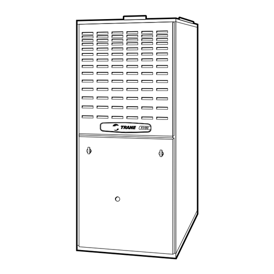
- Page 1 Upflow/Horizontal 80% 2-Stage, Variable Speed Gas-Fired Furnace with Whole House Air Cleaner XV80i TUD2B060AFV32A, TUD2B080AFV32A, TUD2C080AFV42A, TUD2B100AFV32A, TUD2D120AFV52A PUB. NO. 22-1802-03 © 2009 Trane All Rights Reserved...
-
Page 2: Features Summary
Features Summary WHOLE HOUSE AIR CLEANER AIR DELIVERY The Whole House Air Cleaner uses The variable speed, direct drive advanced technology to remove up to blower motor, has sufficient airflow 99.98% of allergens from the filtered for most heating and cooling air and removes particles down to .3 requirements, will switch from microns in size. - Page 3 Feature Summary 2 2 2 2 2 Features and Benefits 4 4 4 4 4 Standard Equipment Optional Equipment 6 6 6 6 6 General Data TUD2B060AFV32A TUD2B080AFV32A TUD2C080AFV42A TUD2B100AFV42A TUD2D120AFV52A Performance Data 8 8 8 8 8 Electric Data...
-
Page 4: Features And Benefits
Features and Benefits XV80i STANDARD EQUIPMENT •Whole House Air Cleaner •Perfect fit door catches •Upflow/Horizontal •Insulated bower door •Power supply 115/1/60 •Gasketed blower door •2-stage gas valve •Two tone color •2-speed venter •Integrated solid state control with •Variable speed ECM blower motor self-diagnostics •Silicon Nitride hot surface igniter with •Common vent capability... - Page 5 Features and Benefits XV80i OPTIONAL EQUIPMENT Thermostat, Mechanical 2-Stage Heating/ 1-Stage Cooling ................TAYSTAT241 [ ] Thermostat, Mechanical Heating Only With Fan Switch .................. BAYSTAT303 [ ] Thermostat, Mechanical Heating Only ....................... BAYSTAT388 [ ] Thermostat, Heating/Cooling Single Stage (Mounts Horizontally) ................ AY28X092 [ ] Electronic Non-programmable Thermostat, 1-Stage Heating/1-Stage Cooling ..........
-
Page 6: General Data
General Data Product Specifications MODEL *UD2B060AFV32A *UD2B080AFV32A *UD2C080AFV42A TYPE Upflow / Horizontal Upflow / Horizontal Upflow / Horizontal RATINGS 2 1st Stage Input BTUH 39,000 52,000 52,000 1st Stage Capacity BTUH (ICS) 3 31,200 41,600 41,600 2nd Stage Input BTUH 60,000 80,000 80,000... - Page 7 General Data Product Specifications MODEL *UD2B100AFV32A *UD2D120AFV52A TYPE Upflow / Horizontal Upflow / Horizontal RATINGS 2 1st Stage Input BTUH 65,000 78,000 1st Stage Capacity BTUH (ICS) 3 52,000 62,400 2nd Stage Input BTUH 100,000 120,000 2nd Stage Capacity BTUH (ICS) 3 80,000 97,000 Temp.
-
Page 8: Performance Data
Performance Data *UD2B060AFV32A Furnace Heating Airflow (CFM) and Power (watts) vs. External Static Pressure With Filter Airflow Dip Switch Setting External Static Pressure Setting Temp. Rise Watts Heating Medium** Temp. Rise 1st Stage Watts High Temp. Rise Watts Temp. Rise Watts Heating Medium**... - Page 9 Performance Data *UD2B080AFV32A Furnace Heating Airflow (CFM) and Power (watts) vs. External Static Pressure With Filter Airflow Dip Switch Setting External Static Pressure Setting Temp. Rise Watts Heating Medium** Temp. Rise 1st Stage Watts 1126 1116 1108 1095 1074 High Temp.
- Page 10 Performance Data *UD2C080AFV42A Furnace Heating Airflow (CFM) and Power (watts) vs. External Static Pressure With Filter Airflow Dip Switch Setting External Static Pressure Setting Temp. Rise Watts Heating Medium** Temp. Rise 1st Stage Watts High Temp. Rise Watts 1064 1077 1085 1086 1077...
- Page 11 Performance Data *UD2B100AFV32A Furnace Heating Airflow (CFM) and Power (watts) vs. External Static Pressure With Filter Airflow Dip Switch Setting External Static Pressure Setting Temp. Rise Watts Heating Medium** Temp. Rise 1st Stage Watts 1029 1040 1039 High Temp. Rise Watts 1118 1138...
- Page 12 Performance Data *UD2D120AFV52A Furnace Heating Airflow (CFM) and Power (watts) vs. External Static Pressure With Filter Airflow Dip Switch Setting External Static Pressure Setting 1003 1039 1062 1033 1034 Temp. Rise Watts 1137 1193 1185 1197 1185 Heating Medium** Temp. Rise 1st Stage Watts 1262...
-
Page 13: Electrical Data
Electrical Data WIRING DIAG WIRING DIAG WIRING DIAG WIRING DIAG WIRING DIAGRAMS FOR GAS FURNACES RAMS FOR GAS FURNACES RAMS FOR GAS FURNACES RAMS FOR GAS FURNACES RAMS FOR GAS FURNACES PUB. NO. 22-1802-03... - Page 14 Electrical Data SCHEMA SCHEMA SCHEMATIC DIAGRAMS FOR GAS FURNACES TIC DIAGRAMS FOR GAS FURNACES TIC DIAGRAMS FOR GAS FURNACES TIC DIAGRAMS FOR GAS FURNACES SCHEMA SCHEMA TIC DIAGRAMS FOR GAS FURNACES PUB. NO. 22-1802-03...
-
Page 15: Field Wiring
Field Wiring FIELD WIRING DIAGRAM FOR VARIABLE SPEED 2 STAGE FURNACE 1 STAGE HEATING USING A 1 STAGE HEATING THERMOSTAT NO COOLING 1. Be sure power agrees with equipment nameplates. 2. Low voltage (24 volt wiring) to be No. 18 A.W.G. min. 3. - Page 16 Field Wiring FIELD WIRING DIAGRAM FOR VARIABLE SPEED 2 STAGE FURNACE 2 STAGE HEATING USING A 2 STAGE HEATING THERMOSTAT NO COOLING 1. Be sure power agrees with equipment nameplates. 2. Low voltage (24 volt wiring) to be No. 18 A.W.G. min. 3.
- Page 17 Field Wiring FIELD WIRING DIAGRAM FOR VARIABLE SPEED 2 STAGE FURNACE 1 STAGE HEATING, 1 STAGE COOLING USING A 1 STAGE HEATING, 1 STAGE COOLING THERMOSTAT (OUTDOOR SECTION WITHOUT TRANSFORMER) W14 JUMPER SEE NOTE 9 OUTDOOR UNIT (NO TRANSFORMER) Y1/Ylo NOTE 7 FIELD ADDED JUMPER W1 TO W2.
- Page 18 Field Wiring FIELD WIRING DIAGRAM FOR VARIABLE SPEED 2 STAGE FURNACE 2 STAGE HEATING, 1 STAGE COOLING USING A 2 STAGE HEATING, 1 STAGE COOLING THERMOSTAT (OUTDOOR SECTION WITHOUT TRANSFORMER) NOTE 9 W14 JUMPER SEE NOTE 9 OUTDOOR UNIT (NO TRANSFORMER) Y1/Ylo NOTE 7 TO 115 V 1 PH.,...
- Page 19 Field Wiring FIELD WIRING DIAGRAM FOR VARIABLE SPEED 2 STAGE FURNACE 2 STAGE HEATING, 2 STAGE COOLING (OUTDOOR SECTION WITHOUT TRANSFORMER) OUTDOOR UNIT NO. 1 (NO TRANSFORMER) SEE NOTE 3 NOTE 7 OUTDOOR UNIT NO. 2 (NO TRANSFORMER) TO 115 V 1 PH., 60 HZ., POWER SUPPLY PER LOCAL CODES...
- Page 20 Dimensions...
- Page 21 NOTES...
- Page 22 Trane 6200 Troup Highway Tyler, TX 75707 Since Trane has a policy of continuous product improvement, it reserves the right to change design and www.trane.com specifications without notice.
Need help?
Do you have a question about the TUD2B060AFV32A and is the answer not in the manual?
Questions and answers