
Related Manuals for Ubiquiti LiteBeam ac LBE-5AC-23


Summary of Contents for Ubiquiti LiteBeam ac LBE-5AC-23
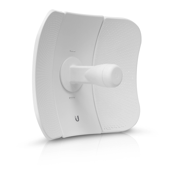
- Page 1 5 GHz, 23 dBi airMAX ® with InnerFeed Technology ® Model: LBE-5AC-23...
-
Page 2: Package Contents
Mounting Bracket Products may be different from pictures and are subject to change without notice. TERMS OF USE: Ubiquiti radio devices must be professionally installed. Shielded Ethernet cable and earth grounding must be used as conditions of product warranty. TOUGHCable ™... -
Page 3: Installation Requirements
AC ground of the PoE. We recommend that you protect your networks from harmful outdoor environments and destructive ESD events with industrial-grade, shielded Ethernet cable from Ubiquiti Networks. For more details, visit www.ubnt.com/toughcable Application Examples The LiteBeam ac mounted outdoors with the reflector installed provides directional outdoor coverage (gain reflector-dependent). -
Page 4: Hardware Overview
Hardware Overview Bottom View Technology LEDs Reset Button Ethernet Port Antenna Feed Reflector Assembly Securing Arms Port Cover Feed Receiver Lock Nut Ball Joint Mount... - Page 5 LEDs Ethernet The LED will light steady blue when an active Ethernet connection is made and flash when there is activity. Power The LED will light blue when the device is connected to a power source. Button Reset To reset to factory defaults, press and hold the Reset button for more than 0 seconds while the LiteBeam ac is already powered on.
-
Page 6: Hardware Installation
Hardware Installation 1. Assemble the antenna reflector by attaching the Side Reflector Panels to the Center Reflector Panel: a. Insert the heads of the two mounting studs on the Center Reflector Panel into the large opening of the slotted holes of a Side Reflector Panel. b. - Page 7 2. Hold the reflector assembly by hand (do not use a tabletop or flat surface) and insert the Feed Receiver into the reflector assembly to secure the panels: a. Align the arrows on the Center Reflector Panel and the Feed Receiver, and insert both edges of the Side Reflector Panels and Center Reflector Panels into the Securing Arms of the Feed Receiver.
- Page 8 WARNING: Do not install the Feed Receiver into the reflector assembly by pushing down onto a tabletop or other flat surface as this can deform the panels. Hold the reflector assembly by hand. 3. (Optional) For additional support, attach four M3x4 self-tapping screws (not included) to the antenna assembly.
- Page 9 4. Attach the Ball Joint Mount to the Feed Receiver by turning the lock nut clockwise by hand. Do not tighten the nut. 5. Insert the Antenna Feed into the Feed Receiver until the feed locks into place.
- Page 10 6. Press both sides of the Port Cover and detach it from the Feed Receiver. 7. Connect an Ethernet cable to the Ethernet port.
- Page 11 8. Reattach the Port Cover. 9. Open the Metal Strap and feed it through the two slots of the Ball Joint Mount.
- Page 12 10. Wrap the Metal Strap around the pole. Use a 7 mm socket wrench or screwdriver to turn the screw clockwise and securely fasten the strap to the pole. 11. Loosen the lock nut on the Ball Joint Mount, and aim at the other end of the wireless link.
Need help?
Do you have a question about the LiteBeam ac LBE-5AC-23 and is the answer not in the manual?
Questions and answers