Table of Contents
Advertisement
Advertisement
Table of Contents

Related Manuals for Volvo Penta 230


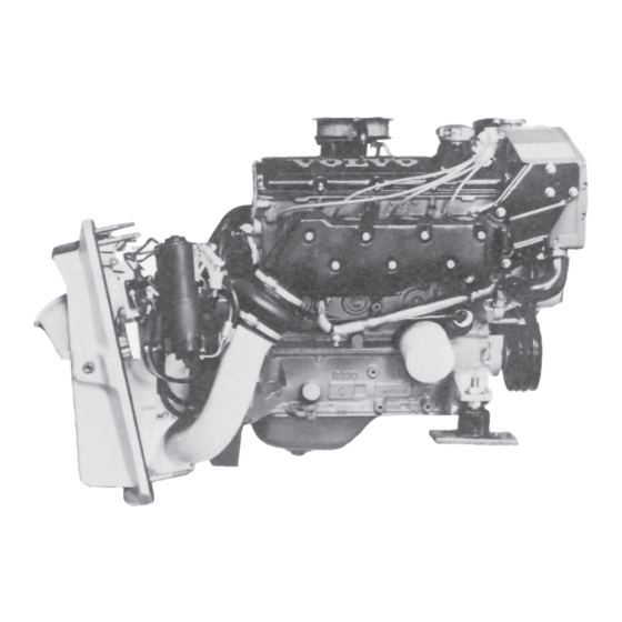
Summary of Contents for Volvo Penta 230
- Page 1 Workshop Manual Engine 2(0) 230, 250, 251DOHC AQ131, AQ151, AQ171...
-
Page 3: Table Of Contents
Trouble-shooting Scheme ..............11 Overhaul Data ................12 Special Tools ................20 Electrical System .................23 Wiring Diagram AQ131, AQ151, 230, 250 Alt. 1......24 Wiring Diagram 230, 250 Alt. 2 ..........26 Wiring Diagram AQ171, 251DOHC Alt.1........28 Wiring Diagram 251DOHC Alt. 2 ..........30 4A. -
Page 4: Safety Precautions
Check that the warning or information decals on This Workshop Manual contains technical data, de- the product are always clearly visible. Replace scriptions and repair instructions for Volvo Penta prod- decals that have been damaged or painted over. ucts or product versions contained in the contents list. - Page 5 Always use protective goggles where there is Store oil and fuel-soaked rags and fuel and oil a danger of pieces of metal, sparks from grind- filters safely. In certain conditions oil-soaked ing, acid or other chemicals being thrown into rags can spontaneously ignite. Used fuel and your eyes.
- Page 6 (gasoline engines) and fuel system on Always check that lifting equipment is in good Volvo Penta products are designed and con- condition and has sufficient load capacity to lift structed to minimize the risk of fire and explo- the engine (engine weight including reverse sion.
-
Page 7: General Information
Replacement parts for electrical and fuel systems tion, descriptions and instructions for repairing the are subject to statutory requirements (US Coast standard versions of the following engines 230, 250, Guard Safety Regulations for example). Volvo Penta 251DOHC, AQ131, AQ151 and AQ171. The product Genuine parts meet these requirements. -
Page 8: Repair Instructions
Warning symbols occurring in the Workshop Manual properly and that Volvo Penta Genuine Parts as used. (for their meaning see Safety information ) The engine Maintenance Schedule must be followed. - Page 9 1/4 turn in one operation after the stated tightening In this Volvo Penta Service Manual the user will find torque has been applied. that each section where these agents are applied in production states which type was used on the engine.
-
Page 10: Presentation
230 replaced AQ131, 250 replaced AQ151and 251DOHC replaced AQ171. 250, AQ151 and 251DOHC, AQ171 are equipped with an oil cooler. 230, AQ131 has a single carburettor and the others have twin carburettors. The exhaust system has seawater cooled exhaust pipes. - Page 11 The Cooling System The sea water cooling system The fresh water cooling system, The fresh water cooling system, thermostat open thermostat closed 1 = Sea-water filter 2 = Heat exchanger 3 = Sea-water pump 4 = Oil cooler 5 = Bypass 6 = Thermostat house 7 = Circulation pump...
- Page 12 The Lubricating System The engine lubricating system from strainer to the main gallery The engine lubricating system from the main gallery to the lubricating points. 1 = Main gallery 2 = Oil pump 3 = Return line 4 = Oil cooler 5 = Oil filter...
-
Page 13: Trouble-Shooting Scheme
Trouble-shooting Scheme Engine Engine Engine runs Engine be- Engine does does not comes abnor- stops not reach op- rough or vi- Fault reason start erating speed brates abnor- mally hot at full throttle mally Main switch open. Battery discharged. Wires broken or fuse blown. -
Page 14: Overhaul Data
1. Overhaul Data Technical Data 230, 250, 251DOHC AQ131, AQ151, AQ171 General Type designation ................. 230, AQ131 Type of engine ..................4 stroke, overhead cam Speed range full load ................78.3–83.3 r/s (4700–5000 rpm) Maximum cruising speed ..............3.33 r/s (200 rpm) lower than the max speed obtained Compression ratio ................ - Page 15 (0.004 in) (in case the engine has an abnormal oil consumption). Pistons Material ....................Light alloy Overall height 230, AQ131 ..............64.7 mm (2.54724") Overall height 250, 251DOHC, AQ151, AQ171 ........61.7 mm (2.42913") Height from gudgeon pin center to top of piston 230, AQ131 ..................
- Page 16 AQ131A, 131B, AQ131C, 131D, 151A, 151B, 151C, 151D, 171C, 171D, 171A, 171B 230, 250, 251DOHC Crankshaft Crankshaft, axial clearance ..............0.080–0.270 mm 0.080–0.270 mm (0.0031–0.0106") (0.0031–0.0106") Main bearing, radial clearance ............. 0.024–0.072 mm 0.024–0.064 mm (0.00094–0.00283") (0.0009–0.0025") Crank bearing, radial clearance ............
- Page 17 0.1–0.4 mm (0.0039–0.0157") Camshaft bearings Camshaft bearing diameter ..............30.000–30.021 mm (1.1811–1.1819") Timing gears, Models 230, 250, AQ131, AQ151 Number of teeth, crankshaft gear ............Number of teeth, intermediate shaft gear ..........Number of teeth, camshaft gear ............Number of teeth, toothed belt ..............
- Page 18 Cold engine ..................0.35–0.40 mm (0.0138–0.0157") Hot engine ................... 0.40–0.45 mm (0.0157–0.0177") The same clearance for inlet and exhaust valves. Valve guides (inlet & exhaust) 230, 250, AQ131, AQ151 Length ....................52 mm (2.165") Inner diameter ..................8.00–8.02 mm (0.275–0.276") Clearance, valve stem–valve guide, inlet valve ........
- Page 19 (0.99 Imp gall./1.19 US gall.) Oil pressure at 33.33 r/s (2000 rpm), hot engine ......... 2.5–6.0 kp/cm (35–85 psi) Lubricating oil, alternative 1 ..............Volvo Penta lubricating oil for gasoline engines Lubricating oil, alternative 2 ..............Lubricating oil SG Viscosity ..................... SAE 20 W/50 Oil filter Type .....................
- Page 20 50 (14x50) Ignition system Cylinder marking ................. No 4 closest to the flywheel Spark plugs 230, 250, AQ131, AQ151 ..........Part no 875820-3, Bosch W6DC or its equivalent Spark plugs, 251DOHC, AQ171 ............Part no 876077-9, Bosch WR6DC or its equivalent Spark plug gap ..................
- Page 21 Distributor 230, 250, AQ131, AQ151 Type ..................... Breaker point system Type Bosch JF4 .................. 0231 178 019 Setting for regular gasoline, min 91 octane ROT: USA: Ignition setting for regular petrol (RON+MON)/2 = min 87 octane Basic setting ..................6° BTDC (0–14.17 r/s = 0–850 rpm) Stroboscope setting ................
-
Page 22: Special Tools
2. Special Tools 884359-1 Drift for the installation of the seal in the flywheel housing 884596-8 Drift for the installation of the primary shaft in the flywheel housing 884599-2 Drift for the installation of the seal in the flywheel housing 884958-0 Drift for the changing of valve guides 251DOHC , AQ171... - Page 23 9994090-0 Puller for support bearing in the flywheel 9995021-4 Press tool for the removal and assembly of the camshaft, AQ131, AQ151, 230, 250 9995022-2 Tool for depressing valve depressors, AQ131, AQ151, 230, 250 9995025-5 Installation tool for the intermediate shaft seal...
- Page 24 Counterhold for the camshaft gear and intermediate gear 9995220-2 Installation tool for valve seats (exhaust), AQ131, AQ151, 230, 250 Reamer, valve guides AQ131, AQ151, 230, 250 9995224-4 9995276-4 Drift for the installation of sealing in the crankshaft rear end 9995283-0...
-
Page 25: Electrical System
(yellow) which is connected to the generator with a thermic 40 A automatic fuse. (GEN) B+. Ignition system AQ131, AQ151, 230 and 250 have conventional breaker point ignition systems. See the “Technical Data” for the setting values. AQ171 and 251DOHC are equipped with breakerless electronic ignition systems. -
Page 26: Wiring Diagram Aq131, Aq151, 230, 250 Alt. 1
Wiring Diagram AQ131, AQ151, 230, 250 With Instrument panel alternative 1 1. Oil pressure gauge 2. Temperature gauge, coolant 3. Voltmeter 4. Tachometer 5. Fuel gauge (alternative) 6. Instrument lighting 7. Key switch (B=30, S=50, I=15) 8. Switch, instrument lighting 9. - Page 27 AQ131, AQ151, 230, 250 ALT. 1...
-
Page 28: Wiring Diagram 230, 250 Alt. 2
Wiring Diagram 230, 250 With Instrument panel alternative 2 1. Tachometer 2. Oil pressure gauge 3. Temperature gauge, coolant 4. Voltmeter 5. Switch, instrument lighting 6. Instrument lighting 7. Key switch (B=30, S=50, I=15) 8. Fuse 8 A 9. Fuse 8 A 10. - Page 29 230, 250 ALT. 2...
-
Page 30: Wiring Diagram Aq171, 251Dohc Alt.1
Wiring Diagram AQ171, 251DOHC With Instrument panel alternative 1 1 . Oil pressure gauge 2. Temp gauge 3. Voltmeter 4. Tachometer 5. Fuel gauge (alternative) 6. Instrument lights 7. Key switch (B = 30, S = 50, I = 15) 8. - Page 31 AQ171, 251DOHC ALT. 1...
-
Page 32: Wiring Diagram 251Dohc Alt. 2
Wiring Diagram 251DOHC With Instrument panel alternative 2 1. Tachometer 2. Oil pressure gauge 3. Temperature gauge, coolant 4. Voltmeter 5. Switch, instrument lighting 6. Instrument lighting 7. Key switch (B=30, S=50, I=15) 8. Fuse 8 A 9. Fuse 8 A 10. - Page 33 251DOHC ALT. 2...
-
Page 34: Fuel System
4A Cylinder Head Trouble shooting and Remedies Fuel System IMPORTANT! Always take the risk of fire into considera- tion and therefore always keep a fire extinguisher near by! Causes Action to be taken Empty tank ......Fill the tank! Closed fuel cock ..... Open the fuel cock! Clogged fuel filter .... -
Page 35: Overhauling And Checking The Carburetor
(1) 4 pcs, and remove the top cover of the carburetor. NOTE! The carburetor on the model 230 (AQ131) is equipped with a full speed jet (A), lower picture. This jet is pressed into the top cover of the carburetor and does not need to replaced unless damaged. - Page 36 Early version Late version 5. Turn the throttle spindle (1) and press out the The Solex carburetor is available with earlier or later thrust rod (2) from the lever (3). Then turn the thrust production versions of the butterfly valve housing. rod downward and remove the check valve (4).
- Page 37 Tighten- ing torque for nuts and screws: 20 Nm (2.0 kpm/14.5 ft.lb). Tool width 12 mm. Late version of AQ131C, AQ131D, 230 = the text turned the right way up. 9. AQ131C, AQ131D, 230. These engines are equipped with a new plate.
- Page 38 6. Then place the butterfly valve shaft between the carburetors and fit them to the intake manifold. 16. Connect the fuel pipe to the fuel pump. Tool 230 (AQ131) does not have a separate butterfly width 12 mm. valve shaft.
- Page 39 Cold start carburetor, function. Start with hot engine. Start with cold engine. When the engine temperature is above 50°C (122°F) When starting, a vacuum is built up in the intake the shut-off valve (3) is closed. The vacuum in the manifold (1).
-
Page 40: Renix Ignition System
4B Renix Ignition System Trouble-shooting and repair ignition system 251DOHC, AQ171 Ignition position sender 19. The crankshaft position sender is located at the rear of the engine and registers the position of the flywheel by reading the ‘teeth’ (machined holes) in the circumference of the flywheel. -
Page 41: Speed Control
The function 23. Half a turn before each explosion cycle the con- trol unit is calculating a very exact pre-ignition going out from the speed of the engine. There are 63 op- timized engine speed values stored in the control unit’s non-volatile memory. - Page 42 2 Ground connection 3 Feeding voltage (15+) 4 Firing position sender connection, red 5 Firing position sender connection, white 26. Use Volvo Penta digital test instrument 6 Is connected but not needed (speed control) 9988452-0 when fault-tracing the RENIX ignition system.
- Page 43 Check the feed voltage Check the crankshaft position sender 27. Remove the plug ‘A’. Switch the ignition on. Con- 30. Remove plug ‘B’. nect a voltmeter to check the voltage between ‘3’ - Measure the resistance of the ignition position sender and ground.
- Page 44 Checking the setting of the crankshaft position sender 38. Set the engine on T.D.C. for no 1 cylinder. In this position the center of the iron core of the sender should be positioned straight above the front edge of the 11th ‘tooth’, (space between the holes), counted back from the ‘long gap’.
- Page 45 Changing the rotor 251DOHC, AQ171 46. Remove the distributor cap, 3 screws. Tool width: 8 mm. 47. Remove and replace the rotor. Re-install the dis- tributor cap.
-
Page 46: Cylinder Head
4C Cylinder Head Removal of the external components 51. Remove the bolts from the heat exchanger 48. Remove the hose (1) from the oil trap and re- bracket. Tool width: 12 mm. move the intake cover. Tool width 10 mm. Take care of the flat washers and the spring washers. - Page 47 57. Pull off the hose (1) from the carburetor and re- move the screw holding the oil dipstick tube. Tool width 1/2". 54. Pull the heat exchanger straight upwards from the cooling water pipes and the cooling water hose. Replace the O-ring on the heat exchanger and the sealing rings on the cooling water pipes.
- Page 48 63. Remove the sea water pump. Tool width: 10 mm. 60. Remove the intake manifold. Tool width: 12 mm. The lifting eyelets are attached to the engine by the upper and outer screws. NOTE! It is only necessary to loosen the lower screws a few turns only.
- Page 49 NOTE! Take care of the guide bushing (1). 71. Remove the thermostat housing and the thermo- 68. 230, 250, AQ131, AQ151. Bring the engine to stat. Tool width: 10 mm. TDC as under paragr. 66. Then ease off the nut of...
-
Page 50: Cooling System
4D Cooling System Overhauling the heat exchanger 75. Lift out the cooling element and the insulating rubber mat from the housing. Pull the cooling ele- ment straight upwards. If necessary use a screw- driver to pry carefully. Clean all parts thoroughly. 72. -
Page 51: Overhauling The Sea Water Pump
78. Insert the rubber mat in the heat exchanger 82. Install the cover and tighten the screws in a housing. criss-cross pattern, a little at the time. NOTE! The cover will be pressed down approx- imately 5 mm (0.25"). Allen key: 4 mm. 79. -
Page 52: Overhauling The Valve System
4E Overhauling the valve system 230, 250, AQ131, AQ151 88. Remove the middle camshaft cap. Tool width: 1/2". 85. Remove the cylinder head. Tool width = 14 mm. Remove the bolts in the sequence shown in the pic- ture. IMPORTANT! In order to avoid scratching the cylinder head it should be placed on wooden blocks. - Page 53 91. Remove the valve tappets and keep them in the same sequence as in the cylinder head. 95. Remove the valve seals from the guides of the intake valves. Use a pair of pliers. Then remove the lower washer (intake). 96.
- Page 54 98. Check the wear of the valve guides. Use new 101. Press in new valve guides. The cylinder head valves and push up the valve 1–2 mm (0.03928– should be at room temperature. Use drift part no 0.07874") with the finger while the measurement is 9995027-1 for the intake and part no 9995028-9 for taken.
- Page 55 The valve seat 105. Knock out the valve seat with a long drift through intake port the cylinder head. 103. IMPORTANT! Always replace the valve guides prior to removing the valve seat. Grind two recesses in the old valve seat ring. These recesses will reduce the tension in the seat ring.
- Page 56 Stellite 109. IMPORTANT! The exhaust valves are ‘Stellite’- coated and must not be reworked! They must only be lapped to seal against the valve seat 107. Find a valve seat with the correct dimension. using grinding compound. In case they are re- The valve seats are not marked but have to be worked, the ‘Stellite’...
- Page 57 112. Check the valve springs in a spring tester. Length, unloaded ....... 45 mm (1.77") loaded 305±20N (67.2±4.48 lbf.) ..38 mm (1.50") loaded 765±40N (170±8.96 lbf.) ..27 mm (1.06") 115. Check that the clearance of the adjustment washer in the valve tappet is not too big. If there are wear marks on the flat surface, it should be re- placed.
- Page 58 Assembling the cylinder head 120. Oil and install the valve tappets along with the 117. Check to make sure that the distance between adjustment washers and in the same location as the valve lock and end of the valve stem is at least earlier.
- Page 59 126. Oil and tighten the last bearing cap. Now tight- 123. Install special tool part no 9995021-4 and press en all the nuts with a torque wrench. Tightening down the camshaft. torque: 20 Nm (2.0 kpm/15 ft.lbs). 124. Lubricate the rubber lip of the camshaft sealing and install it on the camshaft.
- Page 60 132. IMPORTANT! Do not turn either the crank- shaft for the camshaft. The pistons can now hit the valves! Replace the cylinder head bolts in case they show 129. Set the piston for cylinder no 1 at T.D.C. Check signs of elongation. If a bolt is elongated or not can to make sure that the contact surface of the engine be determined by checking the ‘waist’...
-
Page 61: Adjusting The Valves 230, 250, Aq131, Aq151
Adjusting the valves 230, 250, AQ131, AQ151 134. Measure the valve clearance for the number 1 137. Use special tool part no 9995026-3 (pair of pli- cylinder, using a feeler gauge. ers) to lift out the washer. Clearance, cold engine: 0.35–0.40 mm (0.01378–0.01575") Clearance, hot engine: 0.40–0.45 mm (0.01575–0.01772") - Page 62 The kit contains a shim assortment to provide as large an adjustment range as possible. It can be complemented if necessary by ordering from the Volvo Penta Parts Department. The complete kit, part no 884516-4 contains the following parts: Part No:...
-
Page 63: Valve System 251Dohc, Aq171. Technical Description
Spring With two inlet and exhaust valves, the total valve area has increased by approx. 50% compared with the 230 and 250 (AQ131, AQ151). This improves the Tappet cylinder gas flow to the combustion chamber and the fuel/air mixture is burnt more effectively. - Page 64 valve. A certain clearance is also required to ensure that the valve does not remain partly open, allowing combustion gases to pass and the valve to be dam- aged. Preferably, the clearance should be as close to zero as possible. This is possible with hydraulic valve tappets.
-
Page 65: Overhauling The Valve System 251Dohc, Aq171
Overhauling the valve System 251DOHC, AQ171 IMPORTANT! Do not turn either the crank- shaft or the camshaft. The pistons can hit the valves! 146. Lift out the hydraulic valve tappets and place 142. Remove the nuts and the valve cover. Tool them upside down in an oil bath. - Page 66 150. Remove and place the valve locks (1), retainer (2), spring (3) and the lower washer (4) (exhaust) 147. Remove the 5 nuts which attach the camshaft and the valve (5) in the same sequence as removed carrier to the cylinder head. Tool width: 1/2". Then from the engine.
- Page 67 Changing the valve guides 155. Place the cylinder head in special tool part no 153. Use a cutter to clean the valve seats. Remove 884979-6 and hold it with 2 screws (M12). carbon deposits from the combustion chambers and the valves. Check the valves for cracks and other possible damages.
- Page 68 Changing the valve seat The valve seats should, in principle, be changed in accordance with paragraphs 103–108 on pages 53 and 54. Special tool part no 884960-6 for intake and part no 884961-4 for exhaust. 158. Put the new valve guide on special tool part no 884966-3.
- Page 69 Assembling the cylinder head 163. Check the valve springs with a spring tester. Length, unloaded ....... 43 mm (1.6929") loaded 232 N ± 20 N (51±4.48 lbf.) ..37 mm (1.4567") loaded 640 N ± 40 N (141±8.96 lbf.) 26.5 mm (1.0816") 165.
- Page 70 Assembly 171. Tighten the bolts in sequence and in steps. See the illustration. Tool width: 14 mm. 1 = 20 Nm (2.0 kpm/15 ft.lbs) 2 = 40 Nm (4.0 kpm/30 ft.lbs) 3 = angle tightening through 120°. 167. Check to make sure that the number 1 piston is at T.D.C., with the pulley at 0°.
- Page 71 176. Grease the seal ring and install it carefully on the camshaft. 173B. Place the camshaft carrier on the cylinder NOTE! Turn the ‘smooth’ side facing outwards (to- head. Install the 5 nuts by hand. Make sure the car- wards the front). rier enters the end guides.
- Page 72 181. Install new gaskets on the camshaft carrier. 179. Place the camshaft bearing caps 1 to 5 on the The gasket in the middle of the picture can be in- port camshaft. stalled in one way only. The arrow (1) should point NOTE! Caps no’s 1, 5 and 6 should be coated with at no 1 cylinder.
-
Page 73: Installing The Toothed Belt
4F Installing the toothed belt Installing the toothed belt 230, 250, AQ131, AQ151 185. Place the valve cover without the gasket on the cylinder head. Position the marked plate on the two front stud bolts. Then make sure that the marking of the camshaft gear lines up with the plate marking. - Page 74 189. Turn the crankshaft clockwise a few degrees. This is in order to remove the ‘slack’ between the belt wheels. 187. Carefully move the belt onto the belt tensioning NOTE! Do not turn the crankshaft anti-clockwise. roller being careful not to damage the belt. This will cause the belt to jump over giving an incor- rect setting.
-
Page 75: Installing The Toothed Belt 251Dohc, Aq171
Installing the toothed belt 251DOHC, AQ171 193. Turn the belt tensioner to tension the belt and then tighten the Allen-head screw. Tool width: 8 mm. The belt must be tensioned at least once per season and be replaced after every 500 hours of operation. 191. -
Page 76: Installing The External Components Of The Cylinder Head
4G Installing the external components of the Cylinder Head 199. Install the V-belt and tension it to allow it to be depressed approx. 5 mm (0.2") by normal thumb pressure. Tool width: 1/2" and 16 mm. NOTE! Make sure the V-belt enters the correct groove on the crankshaft pulley. - Page 77 202. 251DOHC, AQ171. Install the spark plug leads on the spark plugs and push them into the lead hold- ers. 206. Install the intake manifold together with the car- buretor. Tighten the oil dipstick tube to the intake manifold. Tool width: 1/2" or 13 mm. Then install the hose between the fuel pump and the carburetor.
- Page 78 209. Install the frame arrester cover. Tool width: 10 212. Install the pipe between the oil cooler and the exhaust manifold. Tool width: 10 mm. Check the sealings. Replace if necessary. 210. Connect the hose from the oil trap to the under- 213.
- Page 79 215. Install the cooling water hose on the heat ex- 216. 251DOHC, AQ171. Install the protective cover over the toothed belt/camshaft gear wheels. Tool changer. Tighten the hose clamp properly. width: 10 mm.
-
Page 80: Cylinder Block
5 The Cylinder Block 5A Removing the external components 220. Remove the starter motor. Tool width: 19 mm. 217. Remove the oil dipstick, oil dipstick tube, alternator and the cooling water pipe. Tool width for alternator wires: 10 and 18 mm. 218. - Page 81 225. Remove the drain cock. Tool width: 18 mm. Clean and flush the cooling water jackets properly. 223. Remove the wire from the oil pressure sender. 224. Remove the big nut on the oil cooler. Tool width: 29 mm. Then separate the cooling water tubes from the oil cooler and remove from the en- gine.
-
Page 82: Overhauling The Crank Assembly
226. Remove the flywheel housing as well as the protective plate under the housing and the engine block. Tool width: 19 mm (3/4") and 13 mm. 230. Remove the cross piece carrier from the inter- mediate wheel. Make sure that the cross piece carri- er is not damaged. - Page 83 235. Remove the pilot bearing locking ring for the in- put shaft. 232. Remove the screws in the seal holder. Tool width: 10 mm. The plate is also fixed by two of the bolts holding the oil pan, spanner width: 12 mm. Re- move the seal holder and then remove the seal (1).
- Page 84 241. Remove the rod bearing caps. Tool width: 10 NOTE! The connecting rods and the connecting rod caps are numbered and must not be mixed! 238. Remove the oil pan together with the gasket from the engine. Tool width: 12 mm. 239.
- Page 85 Classification 246. At each cylinder there is a letter punched into the block, giving the class of the bore and that of the piston. Oversizes are categorized as ’ÖD 1’ and ‘ÖD 2’. When reboring a cylinder, the new class must be punched in.
- Page 86 Piston rings 249. Remove the piston rings with piston ring pliers. Remove all carbon deposits. Use a groove cleaning tool to clean the piston ring grooves. A broken off 251. When measuring the piston ring gap, the piston piston ring, ground to shape, can also be used. ring should be inserted into the cylinder.
- Page 87 256. Check the crank bearings and the main bearing journals. Measure with a micrometer at several loca- tions around the diameter and length. The ‘out-of- round’ on main and crank bearing journals must not exceed 0.004 mm (0.000157"). The taper must not exceed 0.004 mm (0.000157") on any of the jour- nals.
- Page 88 262. Use piston ring pliers to install the piston rings. Install the piston rings in accordance with the pic- ture. The upper ring is chromium plated. The lower 259. Install the main bearing caps. compression ring is marked ‘Top’. Turn the piston NOTE! The main bearing caps are numbered 1 to 5, rings on the piston so that the gaps are 120°...
-
Page 89: The Lubricating Oil Pump Overhauling
The lubricating oil pump Overhauling 268. Check the axial clearance. It should be 0.02– 265. Remove the pipe from the lubricating oil pump 0.12 mm (0.00079–0.0047"). and also the 4 screws. Allen key: 5 mm. 269. Insert the piston, spring, guide pin and as- semble the lower part of the pump. - Page 90 273. 230, 250, AQ131, AQ151: Coat the inside of the flywheel with an anti-rust agent, ‘Tectyl’ or its equivalent and install the flywheel. Tightening torque 271. Install the seal holder along with a new gasket 70 Nm (7.0 kpm/51 ft.lbs).
- Page 91 Overhauling the flywheel housing 279. Inspect the flywheel housing and replace all faulty parts. Use the following special tools to remove and install bearings: Part no’s 884359-4, 884596-7 and 884599-4. Make sure you know which way the 276. Check that the O-ring on the underside of the different seal rings are facing prior to removing them.
- Page 92 284. Grease the crankshaft seal abundantly and use 281. Install the protective plate on the underside of special tool part no 9995283-0 to install it. the flywheel housing. Tool width: 1/2". Turn the en- NOTE! gine the right side up. A.
- Page 93 129–133 and pages 70–72, paragraphs 183– mediate shaft. Install the carrier and the carrier 190 for 230, 250, AQ131, AQ151 and pages 68–70, screw. Tighten the screw with a torque of 50 Nm paragraphs 167–182 as well as page 73, paragraphs (5.0 kpm/36 ft.lbs).
- Page 94 292. Check to make sure that the contact surfaces 293. Install the pulley on the circulation pump. Then of the coolant circulation pump and the engine block install the toothed belt, sea water pump, alternator are clean. Put a new seal ring on the pump and a and the V-belt.
-
Page 95: Installing The External Components
5C Installing the external components The distributor 230, 250, AQ131–151 298. Turn the rotor so that the marking on the rotor is pointing approx. 60° away from the marking in the 295. Turn the crankshaft to the firing position for distributor. - Page 96 303. Install the fuse bracket and the wiring harness. Clamp the wiring harness to the flywheel housing Changing the breaker points 230, 251, AQ131, and tighten the ignition coil to its bracket. AQ151 301. Remove the distributor cap (1) and the rotor (2).
-
Page 97: Overhauling The Oil Cooler 250, 251Dohc, Aq151, Aq171
Overhauling the oil cooler 250, 251DOHC, AQ151, AQ171 309. Connect the cooling water pipes along with new rubber sealings to the oil cooler. On model 230, AQ131 the cooling water pipe goes straight from the exhaust manifold to the heat exchanger. The picture shows model 250, AQ151. - Page 98 311. Tighten the oil cooler to the engine. Tool width: 29 mm. 313. Oil the gasket of the oil filter and install the fil- ter by hand until the rubber gasket touches the en- gine block. Then turn the filter by hand a further 1/2 turn.
-
Page 99: References To Service Bulletins
References to Service Bulletins Group Date Regarding .......................................................................................................................................................................................................................................................................................................................................................................................................................................................................................................................................................................................................................................................................................................................................................................................................................................................................................................................................................................................................................................................................................................................................................................................................................................................................................................... - Page 100 Notes ..........................................................................................................................................................................................................................................................................................................................................................................................................................................................................................................................................................................................................................................................................................................................................................................................................................................................................................................................................................................................................................................................................................................................................................................................................................................................................................................
- Page 101 We would prefer you to write in English or Swedish. From: ....................................................................Refers to publication: ............................. Publication no.: ..............Issued: ..............Suggestion/reasons: ....................................................................................................................................................................................................................................................................................................................Date: ............Name: ............AB Volvo Penta Customer Support Dept. 42200 SE-405 08 Gothenburg Sweden...
Need help?
Do you have a question about the 230 and is the answer not in the manual?
Questions and answers
how do u change oil in a 230 B marine engine?