Sign In
Upload
Manuals
Brands
Keysight Manuals
Multimeter
U1272A
User Manuals: Keysight U1272A Digital Multimeter
Manuals and User Guides for Keysight U1272A Digital Multimeter. We have
6
Keysight U1272A Digital Multimeter manuals available for free PDF download: Quick Start Manual, User Manual, Service Manual
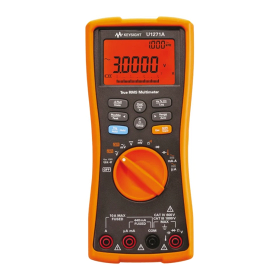
Keysight U1272A User Manual (188 pages)
Handheld
Brand:
Keysight
| Category:
Multimeter
| Size: 12 MB
Table of Contents
Restricted Rights Legend
3
Safety Symbols
4
Safety Considerations
5
Environmental Conditions
7
Table of Contents
11
1 Introduction
22
About this Manual
22
Documentation Map
22
Safety Notes
22
Preparing Your Multimeter
23
Check the Shipment
23
Install the Batteries
23
Figure 1-1 Installing the Batteries
24
Table 1-1 Battery Level Indicator
25
Turn on Your Multimeter
26
Automatic Power-Off
26
Figure 1-2 Start-Up Display
26
Enabling the Backlight
27
Selecting the Range
27
Alerts and Warnings During Measurement
28
Figure 1-3 Input Warning Display
29
Adjusting the Tilt Stand
30
Connecting the IR-USB Cable
30
Figure 1-4 Tilt-Stand Adjustment and IR Cable Connection
30
Remote Control Enabled
30
Figure 1-5 Keysight GUI Data Logger Software
31
Power-On Options
32
Table 1-2 Power-On Options
32
Your Multimeter in Brief
33
Dimensions
33
Figure 1-6 Width Dimensions
33
Figure 1-7 Height and Depth Dimensions
34
Overview
35
Figure 1-8 Front Panel
35
Table 1-3 Front Panel Parts
35
Figure 1-9 Rear Panel
36
Table 1-4 Rear Panel Parts
36
Rotary Switch
37
Figure 1-10 U1271A Rotary Switch
38
Table 1-5 U1271A Rotary Switch Functions
38
Figure 1-11 U1272A Rotary Switch
39
Table 1-6 U1272A Rotary Switch Functions
39
Keypad
41
Figure 1-12 Keys
41
Table 1-7 Keypad Functions
42
Learn more on
43
Display Screen
45
Figure 1-13 Display Screen
45
Table 1-8 General Annunciators
45
Table 1-9 Measurement Units Display
49
Measurement Units
49
Table 1-10 Analog Bar Graph Display
50
Analog Bar Graph
50
Input Terminals
51
Figure 1-14 Connector Terminals
51
Table 1-11 Terminal Connections for Different Measuring
52
Cleaning Your Multimeter
53
2 Making Measurements
55
Crest Factor
56
Measuring AC Voltage
57
Figure 2-1 AC Voltage Display
57
Figure 2-2 Measuring AC Voltage
58
Figure 2-3 AC Voltage with LPF Display
59
Using the LPF (Low Pass Filter) Function for AC Measurements
59
Measuring DC Voltage
60
Figure 2-4 DC Voltage Display
60
Figure 2-5 Measuring DC Voltage
62
Figure 2-6 Filter for DC Voltage Measurements
63
Using the Filter Function for DC Measurement
63
Measuring AC and DC Signals (U1272A Only)
64
Figure 2-7 AC+DC Voltage Display
64
Figure 2-8 Low Pass Filter(LPF) for AC+DC Voltage
65
Using the LPF (Low Pass Filter) Function for AC+DC Measurements
65
Making Db Measurements (U1272A Only)
66
Figure 2-9 Dbm Display
66
Figure 2-10 Dbv Display
67
Using ZLOW for Voltage Measurements (U1272A Only)
68
Figure 2-11 ZLOW Display
69
Using Qik-V for Voltage Measurements (U1271A Only)
70
Figure 2-12 Qik-V Display
70
Measuring Resistance
71
Figure 2-13 Resistance Display
71
Figure 2-14 Measuring Resistance
72
Measuring Conductance
73
Testing for Continuity
74
Table 2-1 Threshold Resistance Values
74
Figure 2-15 Continuity Operation
75
Figure 2-16 Testing for Continuity
76
Using Smart Ω for Resistance Measurements (U1272A Only)
77
Figure 2-17 Smart Ω (with Bias Voltage) Display
78
Figure 2-18 Measuring Leakage Current
79
Testing Diodes
80
Figure 2-19 Diode Display
80
Figure 2-20 Open Diode Display
81
Figure 2-21 Testing Forward Bias Diode
82
Figure 2-22 Testing Reverse Bias Diode
83
Using Auto-Diode for Diode Tests (U1272A Only)
84
Table 2-2 Auto-Diode Voltage Thresholds
84
Figure 2-23 Auto-Diode Display - Good Status
85
Figure 2-24 Auto-Diode Display - Ngood Status
85
Measuring Capacitance
86
Figure 2-25 Capacitance Display
86
Figure 2-26 Measuring Capacitance
87
Measuring Temperature
88
Figure 2-27 Temperature Display
88
Figure 2-28 Measuring Surface Temperature
89
Figure 2-29 Temperature Measurement Without Ambient Compensation
92
Measuring AC or DC Current
93
Figure 2-30 DC Current Display
94
Figure 2-31 Measuring DC Current
95
Figure 2-32 Measuring AC Current
96
Figure 2-33 Current Measurement Setup
97
Figure 2-34 4-20 Ma % Scale Display
98
Scale of 4-20 Ma or 0-20 Ma
98
Table 2-3 % Scale Measurement Range
99
Figure 2-35 Measuring DC Current Using the 4-20 Ma % Scale
100
Frequency Test Mode
101
Figure 2-36 Functions Allowing Frequency Measurement
101
Figure 2-37 Frequency, Pulse Width, and Duty Cycle
102
Measuring Frequency
102
Figure 2-38 Frequency Display
103
Figure 2-39 Pulse Width Display
104
Measuring Pulse Width
104
Figure 2-40 Duty Cycle Display
105
Measuring Duty Cycle
105
3 Multimeter Features
107
Making Relative Measurements (Null)
108
Figure 3-1 Null Display
108
Figure 3-2 Null Operation
109
Making Scale Transfers (Scale)
110
Table 3-1 Available Scale Conversions
110
Scale Transfer Enabled
110
Figure 3-3 Scale Operation
111
Capturing Maximum and Minimum Values (Maxmin)
112
Figure 3-4 Maxmin Display
113
Capturing Peak Values (Peak)
114
Figure 3-5 Peak Display
114
Freezing the Display (Trighold and Autohold)
115
Recording Measurement Data (Data Logging)
116
Data Logging in Progress
116
Table 3-2 Data Logging Maximum Capacity
116
Figure 3-6 Manual Log Display
117
Performing Manual Logs (Hand)
117
Performing Interval Logs (Auto)
118
Figure 3-7 Interval Log Display
119
Performing Event Logs (Trig)
120
Table 3-3 Event Log Trigger Conditions
120
Figure 3-8 Event Log Display
121
Reviewing Previously Recorded Data (View)
122
Figure 3-9 View Display
122
Figure 3-10 Empty View Display
122
View Mode for Reviewing Previously Logged Data
122
4 Multimeter Setup Options
125
Using the Setup Menu
126
Table 4-1 Setup Menu Key Functions
126
Editing Numerical Values
127
Setup Menu Summary
128
Table 4-2 Setup Menu Item Descriptions
128
Setup Menu Items
130
Changing the Beep Frequency
130
Figure 4-1 Beep Display
130
Enabling and Disabling the Filter
131
Table 4-3 Filter (LPF) Options
132
Table 4-4 Firmware Version 2.00 or Older
132
Table 4-5 Firmware Version 2.04 or Newer
132
Changing the Variation Count
133
Figure 4-2 Filter Display
133
Changing the Recording Option
134
Figure 4-3 Ahold Display
134
Changing the Sample Interval Duration
135
Figure 4-4 D-Log Display
135
Changing the Decibel Display (U1272A Only)
136
Figure 4-5 L-Time Display
136
Setting a Custom Dbm Reference Impedance (U1272A Only)
137
Figure 4-6 Dcibel Display
137
Changing the Auto Power-Off and Backlight Timeouts
138
Figure 4-7 Dbref Display
138
Figure 4-8 Apo Display
139
Figure 4-9 Blit Display
139
Enabling and Disabling the Overvoltage Alert
140
Figure 4-10 Alert Display
140
Changing the % Scale Range
141
Figure 4-11 Percen Display
141
Changing the Thermocouple Type (U1272A Only)
142
Figure 4-12 Couple Display
142
Changing the Minimum Measurable Frequency
143
Figure 4-13 Freq Display
143
Changing the Baud Rate
144
Figure 4-14 Baud Display
144
Changing the Data Bits
145
Figure 4-15 Datab Display
145
Changing the Parity Check
146
Figure 4-16 Parity Display
146
Enabling and Disabling the Backlight Alert
147
Figure 4-17 A-Blit Display
147
Enabling Smooth Mode
148
Figure 4-18 Smooth Display
148
Changing the User Scale Conversion Value and Unit
149
Figure 4-19 Smooth Display
149
Resetting the Multimeter's Setup Options
150
Figure 4-20 Reset Display
150
Changing the Temperature Unit
151
Figure 4-21 T-Unit Display
151
5 Characteristics and Specifications
153
5 Characteristics and Specifications
154
Product Characteristics
154
Specification Assumptions
156
Measurement Category
156
Measurement Category Definition
156
Electrical Specifications
158
DC Specifications
158
Table 5-1 DC Specifications
158
AC Specifications
161
Table 5-2 U1271A True Rms AC Voltage Specifications
161
Table 5-3 U1271A True Rms AC Current Specifications
162
Table 5-4 U1272A True Rms AC Voltage Specifications
163
Table 5-5 U1272A True Rms AC Current Specifications
164
AC+DC Specifications for U1272A
165
Table 5-6 U1272A True Rms AC+DC Voltage Specifications
165
Table 5-7 U1272A True Rms AC+DC Current Specifications
166
Capacitance Specifications
167
Table 5-8 Capacitance Specifications
167
Temperature Specifications
168
Table 5-9 Temperature Specifications
168
Frequency Specifications
169
Duty Cycle and Pulse Width Specifications
169
Table 5-10 Frequency Specifications
169
Table 5-11 Duty Cycle and Pulse Width Specifications
169
Table 5-12 Duty Cycle and Pulse Width Calculation Example
170
Frequency Sensitivity Specifications
171
Table 5-13 Frequency Sensitivity and Trigger Level Specifications for
171
Table 5-14 Frequency Sensitivity Specifications for Current
171
Peak Hold Specifications
172
Table 5-15 Peak Hold Specifications for DC Voltage and Current
172
Decibel (Db) Specifications for U1272A
173
Table 5-16 U1272A Decibel Specifications
173
Table 5-17 U1272A Decibel Accuracy Specifications for DC Voltage
173
Measurement Rate (Approximate)
174
Table 5-18 Measurement Rate (Approximate)
174
Shift Functions Using the Shift Key
175
Table A-1 U1271A Default and Shift Functions
176
Table A-2 U1272A Default and Shift Functions
177
Table B-1 U1271A Dual Display Combinations
180
Table B-2 U1272A Dual Display Combinations
182
Advertisement
Keysight U1272A User Manual (167 pages)
Handheld Digital Multimeter
Brand:
Keysight
| Category:
Multimeter
| Size: 13 MB
Table of Contents
Safety Symbols
3
Safety Considerations
4
Measurement Category
6
Environmental Conditions
7
Regulatory Markings
8
Waste Electrical and Electronic Equipment (WEEE) Directive 2002/96/EC
9
Product Category
9
Sales and Technical Support
9
Table of Contents
11
1 Introduction
22
About this Manual
22
Documentation Map
22
Safety Notes
22
Preparing Your Multimeter
23
Check the Shipment
23
Install the Batteries
23
Figure 1-1 Installing the Batteries
24
Table 1-1 Battery Level Indicator
25
Turn on Your Multimeter
26
Automatic Power-Off
26
Figure 1-2 Start-Up Display
26
Enabling the Backlight
27
Selecting the Range
27
Alerts and Warnings During Measurement
28
Figure 1-3 Input Warning Display
29
Adjusting the Tilt Stand
30
Connecting the IR-USB Cable
30
Figure 1-4 Tilt-Stand Adjustment and IR Cable Connection
30
Figure 1-5 Keysight GUI Data Logger Software
31
Power-On Options
32
Table 1-2 Power-On Options
32
Your Multimeter in Brief
33
Dimensions
33
Figure 1-6 Width Dimensions
33
Figure 1-7 Height and Depth Dimensions
34
Overview
35
Figure 1-8 Front Panel
35
Table 1-3 Front Panel Parts
35
Figure 1-9 Rear Panel
36
Table 1-4 Rear Panel Parts
36
Rotary Switch
37
Figure 1-10 U1271A Rotary Switch
38
Table 1-5 U1271A Rotary Switch Functions
38
Figure 1-11 U1272A Rotary Switch
39
Table 1-6 U1272A Rotary Switch Functions
39
Keypad
41
Figure 1-12 Keys
41
Table 1-7 Keypad Functions
42
Display Screen
45
Figure 1-13 Display Screen
45
Table 1-8 General Annunciators
46
Figure 2-29 Temperature Measurement Without Ambient
47
Table 1-9 Measurement Units Display
49
Table 1-10 Analog Bar Graph Display
50
Input Terminals
51
Figure 1-14 Connector Terminals
51
Table 1-11 Terminal Connections for Different Measuring
52
Cleaning Your Multimeter
53
2 Making Measurements
56
Crest Factor
56
Measuring AC Voltage
57
Figure 2-1 AC Voltage Display
57
Figure 2-2 Measuring AC Voltage
58
Figure 2-3 AC Voltage with LPF Display
59
Using the LPF (Low Pass Filter) Function for AC Measurements
59
Measuring DC Voltage
60
Figure 2-4 DC Voltage Display
60
Figure 2-5 Measuring DC Voltage
62
Figure 2-6 Filter for DC Voltage Measurements
63
Using the Filter Function for DC Measurement
63
Measuring AC and DC Signals (U1272A Only)
64
Figure 2-7 AC+DC Voltage Display
64
Figure 2-8 Low Pass Filter(LPF) for AC+DC Voltage
65
Using the LPF (Low Pass Filter) Function for AC+DC Measurements
65
Making Db Measurements (U1272A Only)
66
Figure 2-9 Dbm Display
66
Figure 2-10 Dbv Display
67
Using ZLOW for Voltage Measurements (U1272A Only)
68
Figure 2-11 ZLOW Display
69
Using Qik-V for Voltage Measurements (U1271A Only)
70
Figure 2-12 Qik-V Display
70
Measuring Resistance
71
Figure 2-13 Resistance Display
71
Figure 2-14 Measuring Resistance
72
Measuring Conductance
73
Testing for Continuity
74
Table 2-1 Threshold Resistance Values
74
Figure 2-15 Continuity Operation
75
Figure 2-16 Testing for Continuity
76
Using Smart Ω for Resistance Measurements (U1272A Only)
77
Figure 2-17 Smart Ω (with Bias Voltage) Display
78
Figure 2-18 Measuring Leakage Current
79
Testing Diodes
80
Figure 2-19 Diode Display
80
Figure 2-20 Open Diode Display
81
Figure 2-21 Testing Forward Bias Diode
82
Figure 2-22 Testing Reverse Bias Diode
83
Using Auto-Diode for Diode Tests (U1272A Only)
84
Table 2-2 Auto-Diode Voltage Thresholds
84
Figure 2-23 Auto-Diode Display - Good Status
85
Figure 2-24 Auto-Diode Display - Ngood Status
85
Measuring Capacitance
86
Figure 2-25 Capacitance Display
86
Figure 2-26 Measuring Capacitance
87
Measuring Temperature
88
Figure 2-27 Temperature Display
88
Figure 2-28 Measuring Surface Temperature
89
Compensation
92
Measuring AC or DC Current
93
Figure 2-30 DC Current Display
94
Figure 2-31 Measuring DC Current
95
Figure 2-32 Measuring AC Current
96
Figure 2-33 Current Measurement Setup
97
Figure 2-34 4-20 Ma % Scale Display
98
Scale of 4-20 Ma or 0-20 Ma
98
Table 2-3 % Scale Measurement Range
99
Figure 2-35 Measuring DC Current Using the 4-20 Ma % Scale
100
Frequency Test Mode
101
Figure 2-36 Functions Allowing Frequency Measurement
101
Measuring Frequency
102
Figure 2-38 Frequency Display
103
Figure 2-39 Pulse Width Display
104
Measuring Pulse Width
104
Figure 2-40 Duty Cycle Display
105
Measuring Duty Cycle
105
3 Multimeter Features
108
Making Relative Measurements (Null)
108
Figure 3-1 Null Display
108
Figure 3-2 Null Operation
109
Making Scale Transfers (Scale)
110
Table 3-1 Available Scale Conversions
110
Figure 3-3 Scale Operation
111
Capturing Maximum and Minimum Values (Maxmin)
112
Figure 3-4 Maxmin Display
113
Capturing Peak Values (Peak)
114
Figure 3-5 Peak Display
114
Freezing the Display (Trighold and Autohold)
115
Recording Measurement Data (Data Logging)
116
Table 3-2 Data Logging Maximum Capacity
116
Figure 3-6 Manual Log Display
117
Performing Manual Logs (Hand)
117
Performing Interval Logs (Auto)
118
Figure 3-7 Interval Log Display
119
Performing Event Logs (Trig)
120
Table 3-3 Event Log Trigger Conditions
120
Figure 3-8 Event Log Display
121
Reviewing Previously Recorded Data (View)
122
Figure 3-9 View Display
122
Figure 3-10 Empty View Display
122
4 Multimeter Setup Options
126
Using the Setup Menu
126
Table 4-1 Setup Menu Key Functions
126
Editing Numerical Values
127
Setup Menu Summary
128
Table 4-2 Setup Menu Item Descriptions
128
Setup Menu Items
130
Changing the Beep Frequency
130
Figure 4-1 Beep Display
130
Enabling and Disabling the Filter
131
Table 4-3 Filter (LPF) Options
132
Table 4-4 Firmware Version 2.00 or Older
132
Table 4-5 Firmware Version 2.04 or Newer
132
Changing the Variation Count
133
Figure 4-2 Filter Display
133
Changing the Recording Option
134
Figure 4-3 Ahold Display
134
Changing the Sample Interval Duration
135
Figure 4-4 D-Log Display
135
Changing the Decibel Display (U1272A Only)
136
Setting a Custom Dbm Reference Impedance (U1272A Only)
137
Changing the Auto Power-Off and Backlight Timeouts
138
Enabling and Disabling the Overvoltage Alert
140
Changing the % Scale Range
141
Changing the Thermocouple Type (U1272A Only)
142
Changing the Minimum Measurable Frequency
143
Changing the Baud Rate
144
Changing the Data Bits
145
Changing the Parity Check
146
Enabling and Disabling the Backlight Alert
147
Enabling Smooth Mode
148
Changing the User Scale Conversion Value and Unit
149
Resetting the Multimeter's Setup Options
150
Changing the Temperature Unit
151
5 Characteristics and Specifications
153
Appendix A: 2010-2017Shift Functions Using the Shift Key
155
Table A-1 U1271A Default and Shift Functions
156
Table A-2 U1272A Default and Shift Functions
157
Appendix B: Dual Display Combinations Using the Dual Key
159
Table B-1 U1271A Dual Display Combinations
160
Table B-2 U1272A Dual Display Combinations
162
Keysight U1272A Quick Start Manual (166 pages)
Brand:
Keysight
| Category:
Multimeter
| Size: 21 MB
Table of Contents
Install the Batteries
4
Turn on the Multimeter
4
The Multimeter at a Glance
5
Understanding the Rotary Switch
6
Understanding the Keypad
7
Understanding the Input Terminals
8
Resistance Measurements
12
Continuity Tests
13
Diode Tests
14
Capacitance Measurements
15
Temperature Measurements
16
Current Measurements
17
Guide de Mise en Route
19
Installation des Batteries
20
Mise Sous Tension du Multimètre
20
Brève Présentation du Multimètre
21
Présentation du Commutateur Rotatif
22
Présentation du Pavé Numérique
23
Présentation des Bornes D'entrée
24
Mesures de Résistance
28
Tests de Continuité
29
Tests de Diode
30
Mesures de Capacitance
31
Mesures de Température
32
Mesures de Courant
33
Einlegen der Batterien
36
Einschalten des Multimeters
36
Das Multimeter auf einen Blick
37
Der Drehregler
38
Die Tastatur
39
Die Eingangsanschlüsse
40
Durchführen von Messungen und Tests
41
Guida Rapida
51
Installazione Delle Batterie
52
Accendere Il Multimetro
52
Il Multimetro a Prima Vista
53
Comprensione del Selettore Rotante
54
Comprensione Della Tastiera
55
Comprensione Dei Terminali DI Ingresso
56
Misurazioni DI Resistenza
60
Continuità Test
61
Test del Diodo
62
Misurazioni Della Temperatura
64
Misurazioni DI Corrente
65
Guía de Inicio Rápido
67
Instalación de las Pilas
68
Encendido del Multímetro
68
El Multímetro de un Vistazo
69
El Interruptor Giratorio
70
Los Terminales de Entrada
72
Mediciones de Resistencia
76
Pruebas de Continuidad
77
Pruebas de Diodo
78
Mediciones de Capacitancia
79
Mediciones de Temperatura
80
Mediciones de Corriente
81
ダイオード・テスト
126
입력 단자 개요
136
Guia de Início Rápido
147
Instalar as Baterias
148
Ligue O Multímetro
148
Visão Geral Do Multímetro
149
Noções Básicas sobre a Chave Rotativa
150
Noções Básicas sobre O Teclado
151
Noções Básicas sobre os Terminais de Entrada
152
Medidas de Resistência
156
Testes de Continuidade
157
Testes de Diodo
158
Medições de Capacitância
159
Medições de Temperatura
160
Medições de Corrente
161
Advertisement
Keysight U1272A Quick Start Manual (193 pages)
Handheld Digital Multimeter
Brand:
Keysight
| Category:
Multimeter
| Size: 11 MB
Table of Contents
Install the Batteries
4
Turn on the Multimeter
5
The Multimeter at a Glance
5
Understanding the Rotary Switch
6
Understanding the Keypad
8
Understanding the Input Terminals
9
Performing Measurements and Tests
10
Installation des Batteries
23
Mise Sous Tension du Multimètre
23
Brève Présentation du Multimètre
24
Présentation du Commutateur Rotatif
25
Présentation du Pavé Numérique
26
Présentation des Bornes D'entrée
27
Réalisation de Mesures Et de Tests
28
Einlegen der Batterien
43
Einschalten des Multimeters
43
Das Multimeter auf einen Blick
44
Der Drehregler
45
Die Tastatur
46
Die Eingangsanschlüsse
47
Durchführen von Messungen und Tests
48
Installazione Delle Batterie
62
Accendere Il Multimetro
63
Il Multimetro a Prima Vista
63
Comprensione del Selettore Rotante
64
Comprensione Della Tastiera
66
Comprensione Dei Terminali DI Ingresso
67
Effettuare Le Misurazioni E I Test
68
Instalación de las Pilas
83
Encendido del Multímetro
83
El Multímetro de un Vistazo
84
El Interruptor Giratorio
85
Los Terminales de Entrada
87
Ejecución de Pruebas y Mediciones
88
Instalar as Baterias
174
Ligue O Multímetro
175
Visão Geral Do Multímetro
175
Noções Básicas sobre a Chave Rotativa
176
Noções Básicas sobre O Teclado
178
Noções Básicas sobre os Terminais de Entrada
179
Executar Medições E Testes
180
Keysight U1272A Service Manual (63 pages)
Handheld? U1270 Series
Brand:
Keysight
| Category:
Multimeter
| Size: 4 MB
Table of Contents
Declaration of Conformity
2
Safety Information
2
Safety Symbols
3
Safety Considerations
4
Measurement Category
6
Environmental Conditions
7
Regulatory Markings
8
Waste Electrical and Electronic Equipment (WEEE) Directive 2002/96/EC
9
Product Category
9
Sales and Technical Support
9
Table of Contents
11
1 Calibration Procedures
18
Calibration Overview
18
Closed-Case Calibration
18
Keysight Calibration Services
18
Calibration Interval
19
Adjustment Is Recommended
19
Recommended Test Equipment
20
Table 1-1 Recommended Test Equipment
20
Basic Operating Test
21
Backlight Test (U1271A/U1272A Only)
21
Display Test
21
Current Terminal Input Test
22
Input Warning Display (Μa Ma Terminal)
23
Calibration Process
24
Test Considerations
25
Performance Verification Tests
26
Table 1-2 Performance Verification Tests
28
Calibration Security
35
Unsecuring the Instrument for Calibration
36
To Unsecure the Instrument from the Front Panel
36
To Change the Calibration Security Code
37
To Reset the Calibration Security Code to Its Factory Default
38
Using the Front Panel for Adjustments
40
Adjustment Considerations
40
Valid Adjustment Input Values
41
Table 1-3 Adjustment Input Values
41
Adjustment Procedure
45
Exiting the Adjustment Mode
46
Calibration Count
47
Calibration Error Codes
48
Table 1-4 Calibration Error Codes
48
2 Service and Maintenance
50
Troubleshooting
50
Table 2-1 Operating Checklist
50
Checking the Fuse
51
Table 2-2 Fuse Displayed Readings
52
Testing Fuse 1
53
Testing Fuse 2
54
Fuse Replacement
55
Replacing Fuse 1
56
Replacing Fuse 2
57
Positions of Fuse 1 and Fuse 2
58
Returning the Instrument for Service
59
Replaceable Parts
60
To Order Replaceable Parts
60
Types of Service Available
61
Extended Service Contracts
61
Obtaining Repair Service (Worldwide)
62
Keysight U1272A Quick Start Manual (22 pages)
handheld
Brand:
Keysight
| Category:
Multimeter
| Size: 2 MB
Table of Contents
Install the Batteries
4
Turn on the Multimeter
4
The Multimeter at a Glance
5
Understanding the Rotary Switch
6
Understanding the Keypad
7
Understanding the Input Terminals
8
Voltage Measurements
9
Resistance Measurements
12
Continuity Tests
13
Diode Tests
14
Capacitance Measurements
15
Temperature Measurements
16
Current Measurements
17
Safety Information
19
Safety Symbols
19
Advertisement
Related Products
Keysight U1270 Series
Keysight U1271A
Keysight u1273a
Keysight u1273ax
Keysight U1241B
Keysight U1242B
Keysight U1231A
Keysight U1233A
Keysight U1253B
Keysight U1252
Keysight Categories
Measuring Instruments
Test Equipment
Multimeter
Portable Generator
Power Supply
More Keysight Manuals
Login
Sign In
OR
Sign in with Facebook
Sign in with Google
Upload manual
Upload from disk
Upload from URL