DeDietrich MCR 24, MCR 24/28MI, MCR 30/35MI, MCR 34/39MI Manual
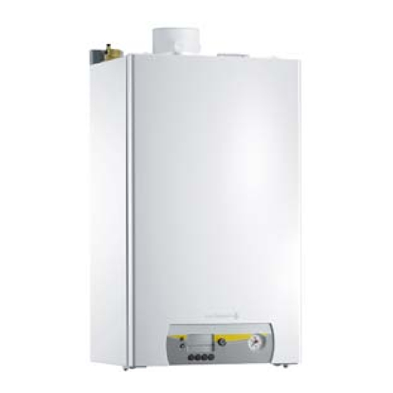
Wall-hung gas condensation boilers
Hide thumbs
Also See for MCR 24, MCR 24/28MI, MCR 30/35MI, MCR 34/39MI:
- User manual (36 pages) ,
- Technical instructions (68 pages)

Related Manuals for DeDietrich MCR 24, MCR 24/28MI, MCR 30/35MI, MCR 34/39MI


Summary of Contents for DeDietrich MCR 24, MCR 24/28MI, MCR 30/35MI, MCR 34/39MI
- Page 1 MCR 24, 24/28MI, 30/35MI, 34/39MI English Wall-hung gas condensation boilers 08/06/06 Instructions for...
-
Page 2: Table Of Contents
Contents Symbols used................3 Recommendations. -
Page 3: Symbols Used
Congratulations on choosing a DE DIETRICH product, a product of quality. We strongly recommend that you read the following instructions in order to guarantee the optimal operation of your appliance. We are sure that you will not be disappointed and that it will satisfy all of your expectations. -
Page 4: Recommendations
Recommendations If you smell gas: Aeration - Do not use a bare flame, do not smoke, do not actuate France: the cross section of the aeration vent, which is compulsory electrical contacts or switches ( doorbell, light, motor, lift, in the premises in which the boiler is installed, must comply with the etc..), DTU 61.1 (P 45 204) standard and, in particular, with the instruction - Cut the gas supply,... -
Page 5: Control Panel
Control panel The control panel of the MCR boiler has 6 function keys, an on/off switch and a screen. A Menu key B Display C Main ON/OFF switch D Pressure gauge E Sweep key F "Escape" or "Reset" key G Heating temperature adjustment key or - H DHW temperature adjustment key or + Maintenance key or enter The display includes 4 positions and several symbols which indicate... -
Page 6: Parameter Display
1 Parameter display The following parameters can be displayed in the information menu - t1 = Flow temperature (°C) - t2 = Return temperature (°C) - t3 = Tank sensor (°C) - t4 = Outside temperature (°C) - FL = Ionisation current (µA) - nF = Fan speed (rpm) - Press the key. -
Page 7: Setting Different Parameters
2 Setting different parameters Parameters P1 to P6 can be modified by the user in order to meet central heating and DHW comfort needs. - Press key several times until the symbol flashes on the menu bar. - Press the key. -
Page 8: Setting The Manual Mode
Factory setting Parameter Description Comments 24/28MI 30/35MI 34/39MI Flow temperature T 20 to 85 °C 75 °C DHW T 40 to 65 °C 55 °C 0 = Heating programme deactivated, DHW programme deactivated 1 = Heating programme activated, DHW programme active Boiler regulation 2 = Heating programme activated, DHW programme... -
Page 9: Modifying The Water Outlet Temperature In The Heating Installation
4 Modifying the water outlet temperature in the heating 5 Switching off the central heating (In summer mode) installation - Starting from the current operating status, press key - The symbol and the current temperature are displayed. - Press the - key until the OFF symbol is displayed. - Press the key to modify the setting. -
Page 10: Setting The Domestic Water Temperature
6 Setting the domestic water temperature - Starting from the current operating status, press key - The symbol and the current temperature are displayed. - Set the temperature using keys + and -. - Press the - key until the OFF symbol is displayed. - Press the key to modify the setting. -
Page 11: Modifying The Comfort Setting (Eco)
7 Modifying the comfort setting (ECO) The user can consult or modify the following 3 settings: - ON = Activation of the energy-saving setting. - OFF = Activation of the comfort setting - AUTO = Setting dependent on the control unit (=Factory setting). - Press the key. -
Page 12: Troubleshooting
Troubleshooting Problem Probable causes Solution Check that the boiler is switched on The boiler is not working Check the fuses and switches Gas stop valve open There is no domestic hot water The water level and/or pressure are too low Check the water pressure in the installation (<1 bar) The energy-saving shower head is allowing too little... - Page 13 Filling, bleeding and draining the installation Filling the heating circuit The water pressure in the boiler must be between 1.5 and 2 bar. Add Switch the boiler off. water to the installation if necessary. LTALW7H000215b - Open the valves on all radiators connected to the heating system. Wait until the temperature drops below 40°C and the radiators seem - Set the room thermostat to as low a temperature as possible.
- Page 14 - Open the valve (1/4 turn). - Close the disconnecteur when the manometer indicates a pressure of 2 bar. - Fill the low flow heating circuit using the drainage tap in order to favor the bleed. - When the pump has stopped, bleed again and top up the water pressure.
- Page 15 Bleeding the heating system It is essential that you bleed any air in the calorifier, the conduits or the taps to prevent the annoying noises likely to be produced during heating or when drawing off water. - Bleed the radiators. - Open the valves on all radiators connected to the heating system.
- Page 16 - Switch on the boiler. A bleed cycle of a duration of around 3 minutes is carried out automatically. - Wait until water comes out of the bleed valve and then close the bleed connection. The water may still be hot. - Check regularly that the installation contains water and is pressurised.
- Page 17 Draining the heating circuit It may be necessary to drain the boiler if the radiators have to be replaced in the event of significant leakage or danger of frost. - Open the valves on all radiators connected to the heating system. - Connect a hose and open the drainage valve at the lowest point of the installation.
- Page 18 MCR boiler off Boiler without antifreeze protection Before any work is carried out on the equipment / heating system, the power supply must be disconnected (by means of the appropriate fuse or main switch, for example) and warning must be given before any reconnection.
- Page 19 Switch on the boiler - Set the boiler regulation to the desired values. The boiler will then operate automatically. - Checking the hydraulic pressure. The hydraulic pressure must be a minimum of 1 bars. Add water to the installation if necessary. Error code If the boiler does not operate normally, an error message is displayed.
-
Page 20: Maintenance And Periodic Checks
Maintenance and periodic checks - Open and close the radiator valves several times a year (this prevents the valves from seizing up). - Checking the hydraulic pressure. Insufficient pressure: add water (1.5 - 2 bar). - Clean the outside of the boiler using a damp cloth and a light detergent. - Page 21 Warranty You have just purchased one of our appliances and we thank you France for the trust you have placed in our products. The preceding dispositions are not exclusive of benefits for the Please note that your appliance will provide good service for a purchaser of the legal guarantee as stated in Civil Code articles longer period of time if it is regularly checked and maintained.
- Page 22 MCR 24, 24/28MI, 30/35MI, 34/39MI 08/06/06 - 300008487-001-A...
- Page 23 08/06/06 - 300008487-001-A MCR 24, 24/28MI, 30/35MI, 34/39MI...
- Page 24 DE DIETRICH THERMIQUE S.A.S. DE DIETRICH HEIZTECHNIK www.dedietrich.com www.dedietrich.com Direction des Ventes France Am Concorde Park 1 - B 4 / 28 57, rue de la Gare A-2320 SCHWECHAT / WIEN F- 67580 MERTZWILLER +43 (0)1 / 706 40 60-0...
Need help?
Do you have a question about the MCR 24, MCR 24/28MI, MCR 30/35MI, MCR 34/39MI and is the answer not in the manual?
Questions and answers