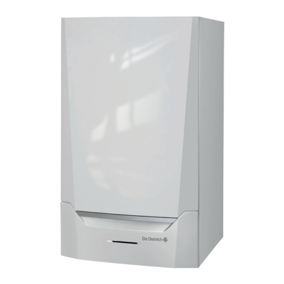
DeDietrich INNOVENS PRO MCA 160 Installation, User And Service Manual
High-efficiency wall-hung
Hide thumbs
Also See for INNOVENS PRO MCA 160:
- Manual (36 pages) ,
- Manual (52 pages) ,
- Technical information (4 pages)

Subscribe to Our Youtube Channel
Related Manuals for DeDietrich INNOVENS PRO MCA 160


Summary of Contents for DeDietrich INNOVENS PRO MCA 160
- Page 1 Ireland PROJECT INNOVENS PRO Installation, User and Service Manual High-efficiency wall-hung gas boiler MCA 160 Inicontrol 2...
- Page 2 Dear Customer, Thank you very much for buying this appliance. Please read through the manual carefully before using the product, and keep it in a safe place for later reference. In order to ensure continued safe and efficient operation we recommend that the product is serviced regularly. Our service and customer service organisation can assist with this.
-
Page 3: Table Of Contents
Contents Contents Safety ................... . 6 General safety instructions . - Page 4 Contents 6.3.3 Connecting the expansion vessel ............27 6.3.4 Connecting the condensate drain pipe .
- Page 5 Contents 10.3 Specific maintenance work ..............63 10.3.1 Replacing the ionisation/ignition electrode .
-
Page 6: Safety
1 Safety Safety General safety instructions For the installer: Danger If you smell gas: 1. Do not use naked flames, do not smoke and do not operate electrical contacts or switches (doorbell, lighting, motor, lift etc). 2. Shut off the gas supply. 3. - Page 7 1 Safety Danger If you smell gas: 1. Do not use naked flames, do not smoke and do not operate electrical contacts or switches (doorbell, lighting, motor, lift etc). 2. Shut off the gas supply. 3. Open the windows. 4. Evacuate the property. 5.
-
Page 8: Recommendations
1 Safety Recommendations Danger This appliance can be used by children aged eight and above and people with a physical, sen sory or mental disability, or with a lack of experi ence and knowledge, provided they are super vised and instructed in how to use the appliance in a safe manner and understand the associated dangers. -
Page 9: Specific Safety Instructions
1 Safety Caution Make sure the boiler can be reached at all times. The boiler must be installed in a frost-free area. If the power cord is permanently connected, you must always install a main bipolar switch with an opening gap of at least 3 mm (EN 60335-1). Drain the boiler and central heating system if you are not going to use your home for a long time and there is a chance of frost. -
Page 10: Liabilities
1 Safety Liabilities 1.4.1 Manufacturer's liability Our products are manufactured in compliance with the requirements of the various Directives applicable. They are therefore delivered with the marking and any documents necessary. In the interests of the quality of our products, we strive constantly to improve them. We therefore reserve the right to modify the specifications given in this document. -
Page 11: About This Manual
2 About this manual About this manual General This manual describes the installation, use and maintenance of the MCA boiler. This manual is part of all the documentation supplied with the boil Additional documentation The following documentation is available in addition to this manual: Installation and user manual for control panel Water quality instructions Symbols used... -
Page 12: Technical Specifications
3 Technical specifications Technical specifications Homologations 3.1.1 Certifications Tab.1 Certifications CE identification number PIN 0063CQ3781 NOx class 6 (EN 15502-1) Type of connection 3.1.2 Unit categories Tab.2 Unit categories Country Category Gas type Connection pressure (mbar) Ireland G20 (H gas) 2H3B/P G30/G31 (butane/propane) 3.1.3... - Page 13 3 Technical specifications Nominal input (Qn) for central heating operation (Hs) G31 (Propane) min. - max. 43.4 - 169.6 Full load central heating efficiency (Hi) (80/60°C) (92/42/EEC) 97.5 Full load central heating efficiency (Hi) (50°C/30°C) (EN15502) 103.6 Low load central heating efficiency (Hi) (return temperature 60°C) 98.4 Part load central heating efficiency (92/42/EEC) (return temperature 108.5...
- Page 14 3 Technical specifications Tab.7 Other data Total weight (empty) Minimum mounting weight (without front panel) Average acoustic level at a distance of one metre from the boiler dB(A) 59.5 Tab.8 Technical parameters Condensing boiler Low-temperature boiler B1 boiler Cogeneration space heater Combination heater Prated Rated heat output...
-
Page 15: Dimensions And Connections
3 Technical specifications Dimensions and connections Fig.1 Dimensions AD-0000100-01 Flue gas discharge connection; Ø 150 mm CH flow connection; 1¼ inch male thread Air supply connection; Ø 150 mm CH return connection; 1¼ inch male thread Siphon connection Gas connection; 1 inch male thread 7667064 - v.01 - 12072017... -
Page 16: Electrical Diagram
3 Technical specifications Electrical diagram Fig.2 Electrical diagram CU-GH06 X04 / X05 1 - 4 1 - 4 1 - 4 X012 X013 X022 X021 X041 X051 X053 X054 X055 X081 X071 X121 X122 X083 X04 / X05 X011 X202 X0141 X201 X014... -
Page 17: Description Of The Product
4 Description of the product Description of the product The MCA 160 boiler is delivered with a combination of the control panel and control PCB. The combination is based on the following software and navigation information: Boiler MCA 160 Important Content of this manual is based on software version 0.17 Name / navigate to: Control panel Inicontrol 2... -
Page 18: Control
4 Description of the product environmental influences (such as limited water flow and air flow prob lems). In the event of such influences, the boiler will not go into lockout mode, but in the first instance will modulate back. Depending on the na ture of the circumstances, a warning, control stop or lock-out may occur. -
Page 19: Circulating Pump
4 Description of the product Before start-up and when the boiler is in operation, the air pressure differ ential switch APS measures the difference in pressure between the meas uring points on the condensate collector p and the air box p . -
Page 20: Main Components
4 Description of the product Main components Fig.4 Main components 1 Air supply 2 Casing/air box 3 Interior light 4 Flow sensor 5 Adapter 6 Heat exchanger 7 Temperature sensor for heat exchanger 8 Ignition transformer 9 Inspection hatch for heat exchanger (x2) 10 Water pressure sensor 11 Return sensor 12 PC/laptop connection point... -
Page 21: Standard Delivery
4 Description of the product Installer menu: parameters at installer level can be changed. Manual mode menu: manual mode can be configured. Error menu: errors can be read out. Hour counter/timer program/time display menu. Control PCB menu: (optional) control PCBs can be read out. The outside temperature sensor is connected. -
Page 22: Accessories And Options
4 Description of the product Accessories and options Various accessories can be obtained for the boiler. Important Contact us for more information. 7667064 - v.01 - 12072017... -
Page 23: Before Installation
5 Before installation Before installation Installation regulations Warning The boiler must be installed by a qualified installer in accordance with local and national regulations. Lifting instruction The weight of the boiler exceeds the maximum lift weight for one person. We recommend the use of a lifting aid. Fig.6 Lifting aids AD-0000138-03... -
Page 24: Location Of The Boiler
5 Before installation 5.3.2 Location of the boiler Fig.8 Installation area Use the guidelines and the required installation space as a basis for de termining the correct place to install the boiler. When determining the correct installation space, take account of the permitted position of the flue gas discharge and/or air supply outlet. -
Page 25: Unpacking & Initial Preparation
5 Before installation Unpacking & initial preparation Fig.10 Unpacking the boiler 1. Cut the packaging straps and remove. 2. Remove the cardboard box. 3. Take the 2 floor stands out of the packaging and place them on the floor in front of the bottom of the boiler. 4. -
Page 26: Installation
6 Installation Installation General Warning The boiler must be installed by a qualified installer in accordance with local and national regulations. Preparation 6.2.1 Positioning the boiler Fig.11 Mounting the boiler The fitting bracket on the back of the casing can be used to mount the boiler directly on the suspension bracket. -
Page 27: Connecting The Heating Circuit
6 Installation 6.3.2 Connecting the heating circuit Fig.12 Connecting the CH flow 1. Remove the dust cap from the CH flow connection at the bot tom of the boiler. AD-0000108-01 Fig.13 Connecting the CH return 2. Fit the outlet pipe for CH water to the CH flow connection. 3. -
Page 28: Gas Connection
6 Installation Fig.14 Connecting the condensate drain 1. Remove the dust cap on the siphon connection at the bottom of the boiler. 2. Push the siphon firmly into the designated opening. The siphon should snap shut with a click. 3. Carefully pull the siphon downwards. 4. - Page 29 6 Installation Tab.11 Types of flue gas connections Type Version Description Open Without down-draught diverter. Flue gas discharge via the roof. Air from the installation area. Open Without down-draught diverter. Common flue gas discharge via the roof (depression). Flue gas discharge rinsed with air, air from the installation area (special construction). Closed Discharge in the outside wall.
-
Page 30: Outlets
6 Installation Tab.12 Shaft dimensions Type Version Diameter Minimum dimensions of shaft or duct Without air supply With air supply Ø duct □ duct Ø duct □ duct Rigid 100 mm 150 mm 150 x 150 mm 150 mm 150 x 150 mm 150 mm 200 mm 200 x 200 mm... -
Page 31: Length Of The Air And Flue Gas Pipes
6 Installation Tab.14 Air supply pipework materials Version Material Single-wall, rigid Aluminium Plastic Stainless steel Flexible Aluminium Plastic Stainless steel 6.5.4 Length of the air and flue gas pipes Room-ventilated version (B Fig.17 Room-ventilated version Connecting the flue gas outlet Connecting the air supply With a room-ventilated version, the air supply opening stays open;... -
Page 32: Specific Air And Flue Gas Applications
6 Installation Connection in different pressure zones (C Fig.19 Different pressure zones Connecting the flue gas outlet Air supply connection Combustion air supply and flue gas discharge are possible in different pressure areas and semi-CLV systems, with the exception of the coastal area. -
Page 33: Connecting The Flue Gas Outlet
6 Installation gether with the condensate must be taken into account the first time. Clean the siphon of the appliance regularly or install an extra conden sate collector above the unit. Make sure that the flue gas outlet pipe towards the boiler has a sufficient gradient (at least 50 mm per metre) and that there is a sufficient conden... -
Page 34: Electrical Connections
6 Installation Electrical connections 6.6.1 Recommendations Warning Electrical connections must always be made with the power supply disconnected and only by qualified installers. The boiler is completely pre-wired. Never change the internal connections of the control panel. Make sure you establish an earth connection before connecting the electricity. -
Page 35: Assembly Of The Control Panel
6 Installation 6.6.3 Assembly of the control panel Fig.23 Control panel The MCA boiler is supplied with a separate control panel. The control pan el is mounted in the boiler. The cable in the box with connector X021 must be slid onto the connector pin (5 pins, 24 V) of the PCB. AD-0000628-02 Fig.24 B Battery... -
Page 36: Connecting The Connection Box
6 Installation 6.6.4 Connecting the connection box Fig.25 Opening the connection box The connection box is included with the delivery of the boiler as standard. Use the connection cables supplied to connect the connection box to the control unit. Proceed as follows: X033 1. -
Page 37: Connection Possibilities For The Standard Pcb (Cb-01)
6 Installation 6.6.5 Connection possibilities for the standard PCB (CB-01) Fig.26 Standard PCB (CB-01) Standard PCB CB-01 can be found in the connection box. Various thermo stats and regulators can be connected to the standard PCB. Pump 0-10 On/off Tout AD-3000672-02 Connecting the system pump Fig.27... - Page 38 6 Installation Fig.30 Internal heating curve 1 Setting point (parameter 2 Comfort base point (parameter 3 Gradient (parameter F Heating curve Outside temperature Flow temperature For more information, see Description of the parameters - FSB-WHB-HE-150-300, page 49 Changing the parameters, page 51 AD-0000871-02 Frost protection combined with outside sensor Fig.31...
- Page 39 6 Installation Analogue temperature regulation (°C) Fig.34 Temperature regulation 1 Boiler on 2 Parameter 3 Maximum flow temperature 4 Calculated value The 0–10 V signal controls the boiler supply temperature. This control modulates on the basis of flow temperature. The output varies between the minimum and maximum value on the basis of the flow temperature set point calculated by the controller.
-
Page 40: Connecting A Pc/Laptop
6 Installation Connecting a PC/laptop Fig.37 Connecting an interface connector There is a Service connector next to the control panel. A Service tool inter face can be used here to connect a: Laptop Smart Service Tool Using the Service tool service software, you can enter, change and read out various boiler settings. -
Page 41: Filling The Siphon
6 Installation Important Reputable manufacturers and their products include: Fernox Sentinel Performance Solution Ltd 6.8.2 Filling the siphon The siphon is supplied separately with the boiler as standard (including a flexible plastic drain hose and a transparent extension hose for the auto matic air vent). -
Page 42: Commissioning
7 Commissioning Commissioning General Follow the steps set out in the paragraphs below to put the boiler into op eration. Warning Do not put the boiler into operation if the supplied gas is not in ac cordance with the approved gas types. Gas circuit Fig.39 Gas measuring point... -
Page 43: Gas Settings
7 Commissioning For more information, see Error codes, page 67 Gas settings 7.6.1 Adjusting to a different gas type Warning Only a qualified engineer may carry out the following operations. The factory setting of the boiler is for operation with the natural gas group G20 (H gas). - Page 44 7 Commissioning 2. Set the fan speed as indicated in the table (if necessary). The set ting can be changed with a parameter setting: Gas fired heat engin - > Description of the parameters - FSB-WHB-HE-150-300, page 49 Changing the parameters, page 51 Tab.24 Factory settings G20 (H-gas) Code...
-
Page 45: Checking/Setting Combustion
7 Commissioning Code Display text Description Range GP009 Fan RPM Start Fan speed at appliance start 900 Rpm - 5000 Rpm 3000 3. Check the setting of the gas/air ratio. Checking/setting combustion, page 45 7.6.2 Checking/setting combustion Fig.41 Flue gas measuring point 1. - Page 46 7 Commissioning Values at full load for G30/G31 (butane/propane) (1) Nominal value Caution The O values at full load must be lower than the O values at low load. 3. If the measured value is outside of the values given in the table, cor rect the gas/air ratio.
-
Page 47: Final Instructions
7 Commissioning Fig.46 Position of adjusting screw B 4. Using the adjusting screw B, set the percentage of O for the gas type being used to the nominal value. This should always be within the maximum and the minimum setting limits. AD-0000140-02 Final instructions 1. -
Page 48: Operation
8 Operation Operation Use of the control panel The display on the control panel provides information about the operating status of the boiler and any errors. The control panel manual for extra information about: Changing, creating and resetting settings. Reading out values. Functions of the panel. -
Page 49: Settings
9 Settings Settings List of parameters The parameters are arranged in three levels: End user level Installer level Advanced installer level The code of the parameters always contain two letters and three numbers. The letters stand for: Appliance related parameters Buffer related parameters Zone related parameters DHW related parameters... - Page 50 9 Settings Tab.35 Gas fired heat engin - > Code Display text Description Range AP001 BL input setting Blocking input setting (1: Full blocking, 2: 1 = Full blocking Partial blocking, 3: User reset locking) 2 = Partial blocking 3 = User reset locking 4 = Backup Relieved 5 = Heat Pump Relieved 6 = Heat Pump And...
-
Page 51: Changing The Parameters
9 Settings Code Display text Description Range PP018 Min CH pump speed Minimum central heating pump speed 20 % - 100 % PP023 Start hysteresis CH Hysteresis to start burner in heating 1 °C - 25 °C mode Changing the parameters The boiler’s control unit is set for the most common central heating sys... -
Page 52: List Of Measured Values
9 Settings Fig.55 Step 10 10. Press the key to confirm the value. MW-3000338-01 Fig.56 Step 11 11. Press the key multiple times to go back to the main display. MW-3000316-01 List of measured values For more information, see Reading out measured values, page 56 9.3.1 Counters - FSB-WHB-HE-150-300 Tab.36... -
Page 53: Signals - Fsb-Whb-He-150-300
9 Settings 9.3.2 Signals - FSB-WHB-HE-150-300 Tab.37 CH (Zone Direct) - > Value Display text Description Range CM030 Zone RoomTemperature Measure of the Room temperature of the -60 °C - 60 °C zone CM120 ZoneCurrentMode Zone Current Mode 0 = Scheduling 1 = Manual 2 = Antifrost 3 = Temporary... - Page 54 9 Settings Value Display text Description Range AM091 SeasonMode Seasonal mode active (summer / winter) 0 = Winter 1 = Winter system frost protection acitve 2 = Summer neutral band 3 = Summer AP078 Out sensor detected Outside sensor detected in the 0 = No application 1 = Yes...
- Page 55 9 Settings Status Burning Central heating Burning Dhw Burner Stop Pump Post Run Cooling Active Controlled Stop Blocking Mode Locking Mode Load test min Load test CH max Load test DHW max Manual Heat demand Central heating On Boiler Frost Protection DeAiration Control unit Cooling Reset In Progress...
-
Page 56: Reading Out Measured Values
9 Settings Sub-status PowerControlOnGradLevel1 PowerControlOnGradLevel2 PowerControlOnGradLevel3 PowerCtrlForFlameProtection StabilizationTime ColdStart ChResume RemoverBurnerOnSuRequest FanToPostPurge OpenExtGasAndFlueGasValveRelay BurnerStopFanToFLueGasValveRpm StopFan LimitedPowerOnTflueGas PumpPostRunning OpenPump Open?HydraulicValveRelay SetBoilerAntiCycleTimer Initialising Done Initialising Csu Initialising Identifiers Initialising Blocking Parameters Initialising Safety Unit Initialising Blocking Reading out measured values 9.4.1 Reading out counters You can read out the counters of the appliance and the connected control boards, sensors and so on. -
Page 57: Reading Out Signals
9 Settings Fig.60 Step 5 5. Press the key to confirm the selection. MW-3000453-01 Fig.61 Step 6 6. Keep pressing the key until the required value is displayed. Tab.44 Counter menu Value Description MW-3000439-01 Resetting service hours Other manuals for more values Fig.62 Step 7 7. -
Page 58: 10 Maintenance
10 Maintenance 10 Maintenance 10.1 General Perform the standard checking and maintenance procedures once a year. Perform the specific maintenance procedures if necessary. Caution Maintenance operations must be completed by a qualified in staller. During inspection or maintenance work, always replace all gas kets of the disassembled parts. -
Page 59: Checking The Flue Gas Discharge/Air Supply Connections
10 Maintenance For more information, see Replacing the ionisation/ignition electrode, page 64 10.2.4 Checking the flue gas discharge/air supply connections Fig.68 Checking flue gas discharge/air 1. Check the flue gas discharge and air supply connections for condi supply connections tion and tightness. AD-0000125-01 10.2.5 Checking the combustion... -
Page 60: Checking The Ps Air Pressure Differential Switch
10 Maintenance 10.2.6 Checking the PS air pressure differential switch Checking the air pressure differential switch + side Fig.69 Check the air pressure differential 1. Switch off the boiler. switch + side 2. Disconnect the silicon hose on the + side (P1) of the air pressure dif ferential switch. -
Page 61: Checking The Automatic Air Vent
10 Maintenance 10.2.7 Checking the automatic air vent Fig.71 Checking the automatic air vent 1. Check the hose on top of the air vent. 2. The automatic air vent is leaking if water can be seen in the connec ted hose. 3. -
Page 62: Checking The Burner And Cleaning The Heat Exchanger
10 Maintenance 10.2.8 Checking the burner and cleaning the heat exchanger Fig.72 Checking the burner 1. Disconnect the plug of the ionisation/ignition electrode from the igni tion transformer. 5 3x Caution The ignition cable is fixed to the ionisation/ignition electrode and therefore may not be removed. -
Page 63: Clean The Condensate Collector
10 Maintenance 10.2.9 Clean the condensate collector Fig.73 Clean the condensate collector 1. Remove the sealing cap from the condensate collector. 2. Rinse the condensate collector thoroughly with a water flow that is as large as possible. Warning During rinsing, avoid penetration of water into the boiler or the control panel. -
Page 64: Replacing The Ionisation/Ignition Electrode
10 Maintenance 10.3.1 Replacing the ionisation/ignition electrode Fig.75 Replacing the ionisation/ignition The ionisation/ignition electrode must be replaced if: electrode The ionisation current is < 4 µA. The electrode is damaged or worn. The electrode is included in the service kit. 1. -
Page 65: Reassembling The Boiler
10 Maintenance 10.3.3 Reassembling the boiler Fig.77 Putting the boiler into operation 1. Fit all removed parts in the reverse order. 2. During inspection or maintenance work, always replace all gaskets of the disassembled parts. 3. Check the tightness of the gas and water connections. 4. -
Page 66: 11 Disposal
11 Disposal 11 Disposal 11.1 Removal/recycling Important Removal and disposal of the boiler must be carried out by a quali fied person in accordance with local and national regulations. To remove the boiler, proceed as follows: 1. Pull the boiler plug out of the socket. 2. -
Page 67: 12 Troubleshooting
12 Troubleshooting 12 Troubleshooting 12.1 Error codes The boiler is fitted with an electronic regulation and control unit. The heart of the control system is a microprocessor, which controls and also protects the boiler. In the event of an error, a corresponding code is displayed. Error codes are displayed at three different levels: Warning ( Important... -
Page 68: Blocking - Fsb-Whb-He-150-300
12 Troubleshooting 12.1.2 Blocking - FSB-WHB-HE-150-300 Tab.47 Blocking codes Code Display text Description Solution H00.36 T 2nd Return Open Second return temperature sensor is Second return temperature sensor open: either removed or measure a Bad connection: check the wiring and temperature below range connectors. - Page 69 12 Troubleshooting Code Display text Description Solution H01.08 Delta T Max 3 Delta T Max 3 Maximum heat exchanger temperature increase has been exceeded: No flow or insufficient flow: Check the circulation (direction, pump, valves). Check the water pressure. Check the cleanliness of the heat exchanger.
- Page 70 12 Troubleshooting Code Display text Description Solution H02.02 Wait Config Number Waiting For Configuration Number Configuration error or unknown configu ration number: Reset H02.03 Conf Error Configuration Error Configuration error or unknown configu ration number: Reset H02.05 CSU CU mismatch CSU does not match CU type Configuration error: Reset...
-
Page 71: Lock-Out - Fsb-Whb-He-150-300
12 Troubleshooting 12.1.3 Lock-out - FSB-WHB-HE-150-300 Tab.48 Lock out codes Code Display text Description Solution E00.00 TFlow Open Flow temperature sensor is either Flow temperature sensor open: removed or measure a temperature Bad connection: check the wiring and below range connectors. - Page 72 12 Troubleshooting Code Display text Description Solution E00.40 WaterPressureOpen Water pressure sensor is either removed Hydraulic pressure sensor open: or measure a temperature below range Bad connection: check the wiring and connectors. Incorrectly fitted sensor: check that the sensor has been correctly fitted. Faulty sensor: replace the sensor.
- Page 73 12 Troubleshooting Code Display text Description Solution E02.17 GVC CommTimeout Gas Valve Control unit communication Communication error with the safety has exceeded feedback time PCB: Bad connection: check the wiring and connectors. Control unit failure: replace the control unit. E02.35 Safety device lost Safety critical device has been disconnected...
- Page 74 12 Troubleshooting Code Display text Description Solution E04.08 Safety input Safety input is open Air pressure differential switch activated: Bad connection: check the wiring and connectors. Pressure in flue gas duct is or was too high: Non-return valve does not open. Siphon blocked or empty.
-
Page 75: Error Memory
12 Troubleshooting Code Display text Description Solution E04.12 False flame False flame detected before burner start False flame signal: The burner remains very hot: Set the Ionisation current measured but no flame should be present: check the ionisation/ignition electrode. Faulty gas valve: replace the gas valve. -
Page 76: 13 Spare Parts
Only replace defective or worn boiler parts with original parts or recom mended parts. Information about available parts can be found via the website for profes sionals. Fig.78 http://pieces.dedietrich-thermique.fr Important When ordering a part, you must state the part number of the re quired part. MW-3000456-01... -
Page 77: Parts
13 Spare parts 13.2 Parts 1011 4005 2001 1012 1010 1009 2044 1011 2025 2006 2026 2023 1012 2027 2005 2039 1008 2004 1016 2043 2007 2008 2022 1010 2009 2024 2040 2013 2010 4005 2011 2022 4030 4007 2015 4031 1003 2025... -
Page 78: 14 Appendix
14 Appendix 14 Appendix 14.1 ErP information 14.1.1 Product fiche Tab.49 Product fiche De Dietrich - MCA Seasonal space heating energy efficiency class Rated heat output (Prated or Psup) Seasonal space heating energy efficiency Annual energy consumption Sound power level L indoors For specific precautions in relation to assembly, installation and maintenance: Safety, page 6... -
Page 79: Checklist For Commissioning
14 Appendix 14.3 Checklist for commissioning Tab.50 Checklist Commissioning tasks Confirmation Fill the system with water and check the water pressure Fill the siphon with water Vent the central heating system Check water-side connections for tightness Check the gas supply pressure Check the capacity of the gas meter Check the gas tightness of the connections and gas pipes Vent the gas supply pipe... -
Page 80: Checklist For Annual Maintenance
14 Appendix 14.4 Checklist for annual maintenance Tab.51 Checklist for annual maintenance Inspection and/or servicing work Confirmation Check the water pressure Check the water quality Check the ionisation current Check the air supply/flue gas discharge connections Check the combustion (O ) at full load and low load Checking the automatic air vent Checking the burner and cleaning the heat exchanger... -
Page 81: V.01 - 12072017 Mca
14 Appendix 7667064 - v.01 - 12072017... - Page 82 14 Appendix 7667064 - v.01 - 12072017...
- Page 83 © Copyright All technical and technological information contained in these technical instructions, as well as any drawings and technical de scriptions supplied, remain our property and shall not be multiplied without our prior consent in writing. Subject to alterations.
- Page 84 L- 2549 LUXEMBOU RG B- 8500 KORTRIJK +352 (0)2 401 401 +32 (0)56/23 7 5 11 www .neuberg.lu www .vanma rcke.be www .dedietrich-heating .com DE DIETRICH SERVICE DE DIETRICH THERMIQUE beria S.L.U C/Salv ador Espriu, 11 0800 / 20 1608 freecall 08908 L’HOSPITALET de LL O BREGAT...
Need help?
Do you have a question about the INNOVENS PRO MCA 160 and is the answer not in the manual?
Questions and answers