
Related Manuals for urmet domus 1148 Series


Summary of Contents for urmet domus 1148 Series
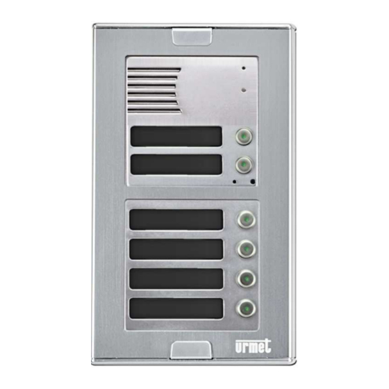
- Page 1 Mod. 1148 DS1148-014D UNIVERSAL COMBIPHONE DOOR UNIT Ref. 1148/1 Ref. 1148/2 Ref. 1148/4-6-14 INSTALLATION, PROGRAMMING AND FUNCTIONS MANUAL...
-
Page 2: Table Of Contents
Table of Contents BASIC FEATURES ..................... 3 SYSTEM MODULES ..................4 INSTALLATION ACCESSORIES ............4 BASIC MODULE CONNECTION ............6 WIRING AND FLAT CABLE CONNECTION IN DETAIL ....10 1148/6 KEYBOARD CONNECTION ..........12 INSTALLATION OF THE DEVICES ..........13 CONNECTION .................. -
Page 3: Basic Features
1 BASIC FEATURES The combiphone module Sinthesi S2 is a modular system that allows to install up to • 99 buttons Voice communication is based on a telephone line: the module can be connected as • a PABX analogue extension or directly under an analogue telephone line Impulse and tone (DTMF) options •... -
Page 4: System Modules
2 SYSTEM MODULES The structural components of the system are: basic modules equipped with one or two buttons (1148/1 or 1148/2), 4-buttons modules (1148/4 and 1148/14), numeric keypad module (1148/6). 1148/1 1148/2 1148/4 1148/6 1148/14 2.1 INSTALLATION ACCESSORIES MODULE HOLDER WITH FRAME FOR FLUSH-MOUNTING INSTALLATION 1148/61 1148/62 1148/63... - Page 5 FLUSH-MOUNTING BOX 1145/51 11458/52 1145/53 1145/54 HOUSING WITH HOOD AND WALL FRAME FOR WALL INSTALLATION, TO BE COMPLETED WITH 1148/61-62-63-64 MODULES 1148/311 1148/312 1148/313 1148/314 1148/324 1148/326 DS1148-014D...
-
Page 6: Basic Module Connection
RAIN HOOD FOR FLUSH-MOUNTING INSTALLATION 1158/611: for 1 module (1 row) 1158/612: for 2 modules (1 row) 1158/613: for 3 modules (1 row) 1158/614: for 4 modules (1 row) FRAMES ASSEMBLY EXAMPLES 2.2 BASIC MODULE CONNECTION The basic module is offered in 2 different options: with two buttons Ref.1148/2 and with one button Ref.1148/1. - Page 7 Microphone (placed on the lower part of the motherboard) – be careful of the rubber seal of the microphone when changing the name tags, as the improper assembly may affect the acoustics. Connection expansion buttons modules and keyboard Connection point for a PC USB cable for PC connection. LED indicator (placed on the lower part of the motherboard) Speaker –...
- Page 8 POWER SUPPLY - TERMINAL (6): Use the power supply 9000/230 for the following functions: - relay control; if the relays are used on 7 or 8 mode, the dip switches 3 and 4 must be ON and it’s necessary to set the parameter 64. - motherboard heating (DIP 2 switches on, regulation of current according to voltage and temperature) - name tag back lighting (DIP 5 switches on)
- Page 9 MODULES CONNECTION: REF.1148/4 and REF.1148/14 Button add-on modules are either active Ref. 1148/4 (contains electronics) or passive Ref.1148/14 (mechanical module Urmet – only buttons). The first add-on next to the basic module must be an active module (4 buttons). An active module is connected with a flat cable K - 10 wires (be careful about the direction of the connection).
-
Page 10: Wiring And Flat Cable Connection In Detail
2.3 WIRING AND FLAT CABLE CONNECTION IN DETAIL Img. 2 Connection of the modules 1148/4 and 1148/14, one level 1) Flat cable towards basic modules 2) Flat cable towards expansion modules 3) Electrical connection for 1148/14 module 4) Connection for nametag lighting 5) Alternative connection for nametag lighting DS1148-014D... - Page 11 MODULES CONFIGURATION EXAMPLE 1148/1-2 1148/4 1148/14 1148/4 1148/14 Img. 3 Connection of the modules 1148/4 and 1148/14, two level DS1148-014D...
-
Page 12: 1148/6 Keyboard Connection
2.4 1148/6 KEYBOARD CONNECTION The connection of the keyboard module is done with one of the 2 flat cables furnished, starting from the module 1148/1-2 or 1148/4; the only difference is that the keyboard module can only be connected to the first 8 places following the basic modules. In addition to that, the keyboard module must be the last one of the modules connected. -
Page 13: Installation Of The Devices
The keyboard has 2 basic modes for dialling the phone numbers (parameter 49). Direct choice of phone numbers – press numbers on the keyboard like you • would on a phone (max. 24 digits) Choice from the door system’s memory – press only 2 digits on the •... - Page 14 The relay (Img.1 7) have multiple uses; some connection examples are shown on the next page. To make the system work properly you need to connect the power supply 9000/230. The Door Phones system is designed so that all parts are galvanically isolated.
- Page 15 RELAY CONNECTION EXAMPLES EXAMPLE 1 Power Supply Electric lock 1 Electric lock 2 EXAMPLE 2 For relay lighting and control Power Supply Electric lock 1 Electric lock 2 Power Supply To power the electric lock EXAMPLE 3 Power Supply Additional bell Electric lock 1 DS1148-014D...
-
Page 16: Accessories
Basic connection: 2 electric locks and the possibility to manage two doors independently (relay mode 1 and 2 m = 1) or the gradual opening of a door (relay mode 2 m = 5). Two power supplies: ability to use two power supplies, one for the 1148/1 module or / 2 and one for an electric door lock. -
Page 17: Door Entry System Operation
3 Door Entry System Operation The door entry system’s functions are set by establishing parameters (see the section of parameter programming). 3.1 Signalling overview The combiphone Sinthesi S2 acoustic signals occur during its operation. Samples of sounds can be listened to in the setting programme Urmet-1148-tel. State Tones Tone frequency... - Page 18 is also connected to the combiphone, the user can press a DTMF code on his phone and let visitor in. If he hangs up the phone the combiphone will disconnect. If the call lasts longer than the pre-set limit (parameter 52), 10sec before disconnection the combiphone will send a line disconnection tone, but the user can dial * or # (parameter 42), to prolong the call for the length of time set in parameter 52.
- Page 19 3.2.1 Tab. 1 – Table of relay controls Mode m = 1 (parameter 3111 and 3121) Action Note Parameter Relay Evaluation of correct 3211-3215 internal code from 3311-3315 According to setting the buttons Day/Night 3411-3415 3221-3225 3321-3325 According to setting Day/Night 3421-3425 321*...
-
Page 20: Outbound Call
Mode m = 4 Action Note Parameter Relay Press buttons 3114 number other than in 311* or 312* 3124 3114 Button set in 311* or 312* 3124 Mode m = 6 Action Note Parameter Relay Press of the button 3116 number other than in 311* or 312*... -
Page 21: Door Entry System With Keyboard - 1148/6 Module
The final exception is relay controls (parameter 381 and 382), when an incoming • call can disable the relay controls. 3.2.4 Door Entry System with keyboard – 1148/6 module If a keyboard module is connected to the system, then it is necessary to set the following parameters: parameter 48 –... -
Page 22: Acoustic Path Setting
3.3 Acoustic path setting The principle of setting acoustic paths: Here we have three parameters 71.72 and 73 Using the interaction of these parameters can be set to sound in different conditions. Quiet environment parameters 71,72,73 are set to 7 Environment where is a strong ambient noise at the communicator and quiet environment at the phone. -
Page 23: Parameter Programming
4 Parameter programming 4.1 Programming with the help of a phone 4.1.1 Entry into the programming There are two ways to enter the combiphone programming system: With the help of a password –incoming calls only! – pick up a phone and dial the number that the combiphone is connected to (either the number of the branch, if you are connected to a switchboard line, or the number of the line to the building, where the combiphone is and ask to be connected to the branch... -
Page 24: Description Of Programmable Parameters
5 Description of programmable parameters Parameters always start with a fixed/mandatory part (address) followed by a variable part, which is your choice. The range and explanation is always under the table, sometimes with examples. Everything is dialled exactly as it is shown in the table, nothing needs to be confirmed in any way, after writing into a memory a confirmation tone can be heard and if an incorrect value is input then an error tone will be heard. -
Page 25: Relays
5.2 Relays Parameter Value Meaning Basic relay r operates in mode m (1-8) 11 21 – relay number [1-2] m – relay mode [1-8 for r=1 is not mode m=5] The modes m=1, 4, 5, 6 are explained in detail in Relay Modes Table. m=1 mode relay –... - Page 26 Parameter Value Meaning Basic In Day + Night mode password hh... for rp hh... relay r, in order p=1-5 for 1 impulse and p=* for 2 impulses (00-999999) In Day mode password hh... for relay r, in rp hh... order p=1-5 for 1 impulse and p=* for 2 impulses (00-999999) In Night mode password hh...
- Page 27 By choosing no 8 on the phone we switch on just the second relay, with option 48 we switch on both relays Parameter Value Meaning Basic command aa from phone for switching r cc 150 260 relay r 2 impulses (00-99,*0-*9) –...
-
Page 28: Basic Parameters
Parameter Value Meaning Basic time zz [sec] between impulses for r zz switching on relay r 2 impulses- time t2/t5 105 205 (01-99) – relay number [1-2] – time t2 / t5 between first and second impulse for switching on relay 1 / 2 [2 spaces 00-99], where time 00 means 0,5sec Parameter Value... - Page 29 Once the combiphone picks up the system is in programming mode. In this mode it is possible to change the password 44xxxx Switch ‘DIP 1’ to ‘OFF’ Close the front cover. Parameter Value Meaning Basic Command for switch over to DAY (00-9,*0-*9) Command for switch over to NIGHT (0099,*0-*9)
-
Page 30: Time Parameters
d=1 DTMF can be dialled, the Key button dials * d=2 DTMF can be dialled, the Key button dials # d=3 DTMF can be dialled, the Key button dials A Parameter Value Meaning Basic Line disconnection function by repeatedly pressing a button (0/1) k –... - Page 31 Switch on Relay – if the time between presses is longer than the time w then the code will not work correctly. Choosing of number Choose from the phone, if the time after the last pressed button is longer than time w, then the choice commences, if the number is incomplete, it is necessary to disconnect (press the X key ) and repeat the choice...
- Page 32 Parameter Value Meaning Basic Tone length of time for DTMF (tone) choice 10 (100ms) (04-16) Time of gap between DTMF tones (04-16) 10 (100ms) Length of flash time (1-6) 1 (100ms) Length of time of pause/digit gap (1-0) 4 (800ms) tt Length of DTFM tone choices is specified by the formula: (entered number) x 10 = time length of tone [ms] frequency...
-
Page 33: System Parameters
5.5 System parameters Parameter Value Meaning Basic Acoustic signals (confirmation, error, empty memory, end of call) (0/1) The combiphone comes with standard acoustic signals. However, using parameter “z” it is possible to switch off the acoustic signals. The values are: Acoustic signals off / z=1 Acoustic signals on. - Page 34 Note2 During the relay switch-on (2 impulses) there is acoustic signal for the whole time of the sequence (even during gap between impulses). Parameter Value Meaning Basic Suppression of the reception DTMF from the microphone (0/1) Suppression of the reception DTMF from the microphone is off as a default i=0. It is possible to open the door with a personal dialler without disturbing a person inside the building.
-
Page 35: Parameter Setting Hands Free
Parameter Value Meaning Basic Delayed start for no-Urmet switchboards with line testing (0/1) This function is off as standard t=0. By switching this function on t=1 the processor goes into sleep mode immediately after the line connection, and after 3 secs. The combiphone initialises. - Page 36 Suppression of background noise (0/1) By default this function is set to ON (n=1), suitable for noisy location. This is related to setting of parameters 71, 76, 77. Parameter Value Meaning Basic Threshold for switching on the microphone 1-4 (4 is the highest) There is a simultaneous signal from the microphone and the speaker on the telephone line, to ensure that the combiphone doesn’t produce acoustic feedback.
- Page 37 standard k=0, but it is possible to set on 2 levels, depending on the current that switchboard can supply (short circuit current I k - choice Switchboard current I Function off 20mA-50mA 45mA-75mA Parameter Value Meaning Basic Level of signal transmission v [-dBm] (04-16) The signal transmission range to the line is -4 to -16dBm, entered is required level, which is uu=04 is -4dBm, uu=10 is -10dBm ...
-
Page 38: Basic Setting And Deletion
6 Basic setting and parameters Reset Parameter Value Meaning Basic Basic setting provide This setting does not affect parameters 1 and 2 (numbers saved in memory) Parameter Value Meaning Basic Deletes all numbers in 1st group (Day mode) Deletes all numbers in 2nd group (Night mode) Basic setting only for parameters 3x only 3.. -
Page 39: Parameter Overview
6.2 Parameter overview Parameter Value Meaning Basic tt nn… number nn under button tt tt nn… number nn under button tt relay r works in m (1-8) mode 11 21 button tt causes switching on of relay r in r* tt m=6 mode (01-99) In DAY + NIGHT mode password hh... - Page 40 Parameter Value Meaning Basic Choice DTMF from the keyboard during a call (0-3) Line disconnection by repeat press of the same button (0/1) Number of rings before the combiphone picks up (1-9) Maximum length of call (0-9,*,#) Time between button presses (1-9) Time of disconnection for repeat choice (1-5) Time before choice begins (1-5)
- Page 41 Parameter Value Meaning Basic Mute at the lock activated (0/1) Setting of number of buttons on the main panel Delayed start for switchboards with line tests (Siemens) (0/1) Reception volume 01-16 (16 is the highest) (SPK) Transmission volume 01-16 (16 is the highest) (MIC) Speaker volume 01-16 (16 is the...
-
Page 42: Technical Parameters
7 Technical parameters Parameter Value Conditions Minimum line current 18mA Line picked up Minimum line voltage Line disconnected Voltage on the line when the < 8V I = 20mA combiphone picks < 12V I = 60 mA characteristic) Lead in in disconnected state <... - Page 43 8 Table for easy programming Fill in the values you want to programme into the empty part of the table, in the double framed part there are whole programming commands to make programming easier. You can keep the programmed values in the manual for future changes. Meaning Programming sequence N°...
- Page 44 Day+Night Passw. for relay 1 (1 imp.) 3214 Day+Night Passw. for relay 1 (1 imp.) 3215 Day+Night Passw. for relay 1 (2 imp.) 321* Day+Night Passw. for relay 2 (1 imp.) 3221 Day+Night Passw. for relay 2 (1 imp.) 3222 Day+Night Passw.
- Page 45 Switch on r 2 from phone 1 impulse Switch on r 1 from phone 2 impulses Switch on r 2 from phone 2 impulses Length of time for r 1 switch on [sec] Length of time for r 2 switch on [sec] Control of r 1 during incoming call 1 / 0...
- Page 46 Length of time of permanent tone Length of time of tone choice nn x 10 Gap between DTMF tones nn x 10 Length of time Flash n x 100 Length of time of pause / gap n x100+400 Transmitting level DTMF 04-16 -dBm preemphase DTMF...
-
Page 47: Basic Connection Diagram
9 Basic connection diagram DS1148-014D... - Page 48 DS1148-014D URMET S.p.A. Technical Assistance Customer Service 10154 TORINO (ITALY) +39. 011.23.39.810 VIA BOLOGNA 188/C http://www.urmet.com Telef. +39. 011.24.00.000 (RIC.AUT.) e-mail: info@urmet.com Fax +39. 011.24.00.300 - 323 DS1148-014D Prodotto nella Repubblica Ceca su specifica URMET Made in Czech Republic to URMET specification...
Need help?
Do you have a question about the 1148 Series and is the answer not in the manual?
Questions and answers