
Related Manuals for True CS200


Summary of Contents for True CS200
- Page 1 *Assembly Guide & Warranty Card Included CS200 UPRIGHT BIKE OWNER’S MANUAL Revision 031715...
- Page 2 CS200 UPRIGHT BIKE OWNERS MANUAL IMPORTANT: All Products shown are prototype. Actual product delivered may vary. Product specifications, features & software are subject to change without notice. For the most up to date owner’s manual please visit www.truefitness.com. For documents in additional languages please visit www.truefitness.com/document-library/29/international-manuals IMPORTANTE: Todos los productos mostrados son prototipos.
- Page 3 The proud manufacturing tradition of quality and the culture of innovation at TRUE have given rise to a full line of truly extraordinary treadmills, indoor cycles and elliptical cross-trainers. As a result, people all over the world are benefiting from the TRUE experience.
-
Page 4: Table Of Contents
CS200 UPRIGHT BIKE OWNERS MANUAL TABLE OF CONTENTS: Chapter 1: Safety Instructions Chapter 5: Care & Maintenance Safety Instructions Care & Maintenance Space Requirements Cleaning the Equipment Grounding Instructions Leveling the Unit Power Requirements Other Scheduled Preventive Maintenance Warning Decals... -
Page 5: Chapter 1: Safety Instructions
45, smokes, has high cholesterol, is obese or has not exercised regularly in the past year. Additionally, TRUE recommends consulting a fitness professional on the correct use of this product. - Page 6 To disconnect plug remove from electrical outlet. • The CS200 bike is self-generated and does not require the use of an electrical outlet. Optional power supplies require 110V AC input and 9V DC 1.5Amp output for console operation only. •...
-
Page 7: Space Requirements
SPACE REQUIREMENTS: • TRUE’s recommendation is to leave a 39” safety zone at rear of bike. The sides of the bike should be at least 20” away from the wall or obstructions. (See Fig 1) Truefitness.com / 800.426.6570 / 636.272.7100... -
Page 8: Grounding Instructions
CHAPTER 1 SAFETY INSTRUCTIONS GROUNDING INSTRUCTIONS: This product must be grounded, if it should malfunction or breakdown, grounding provides a path of least resistance for electric current to reduce the risk of electric shock. This product is equipped with a cord having an equipment-grounding conductor and a grounding plug. -
Page 9: Power Requirements
CHAPTER 1 SAFETY INSTRUCTIONS Truefitness.com / 800.426.6570 / 636.272.7100... -
Page 10: Warning Decals
CHAPTER 1 SAFETY INSTRUCTIONS WARNING DECALS: WARNING: Replace warning labels that may be worn, damaged or missing. To replace any worn or missing warning decals contact TRUE FITNESS by one of the following: www.truefitness.com or contact customer service at 800-883-8783. COMPLIANCES: This equipment complies with all applicable codes and regulations. -
Page 11: Chapter 2: Assembly Instructions
• Save these instructions. • Should you need technical assistance in assembly of your TRUE Fitness product, contact TRUE Fitness Technical Support at 1-800-883-8783. PRE-ASSEMBLY CHECK LIST: Assembly Hardware Kit: Tools Required:... -
Page 12: Bike Assembly Steps
CHAPTER 2: ASSEMBLY INSTRUCTIONS BIKE ASSEMBLY STEPS: Step 1 Front Stabilizer Bar: a) Using 6mm hex key assemble Front Stabilizer to the front of the bike with two Screws, two Lock Washers, and two Flat Washer s. *Install with wheels forward as shown. Hardware Required: 2 M10 x 55 Screws (X07) 2 M10 Washers... - Page 13 CHAPTER 2: ASSEMBLY INSTRUCTIONS BIKE ASSEMBLY STEPS (continued): Step 3 Mast Connections and Installation: a) Slide Mast Boot onto Mast. b) Connect the following electrical connections between the Mast and Mast Post: • Control cable (W08) *7-pin and 5-pin connectors. •...
- Page 14 CHAPTER 2: ASSEMBLY INSTRUCTIONS BIKE ASSEMBLY STEPS (continued): Step 5 Balance Bar Installation: a) Route Mast cables out of center access hole in mast flange as shown b) Route two 3-pin contact heart rate connectors (W07) and cables from balance bar into hole in back of Mast and then out of top of mast with other cables.
- Page 15 CHAPTER 2: ASSEMBLY INSTRUCTIONS BIKE ASSEMBLY STEPS (continued): Step 7 Console Assembly (continued): b) Attach the GROUND cable to the ground screw on the console mast. c) Tuck excess cable length into the mast. GROUND Screw d) Secure the console to the console mast using the 4 screws included with the console.
- Page 16 CHAPTER 2: ASSEMBLY INSTRUCTIONS BIKE ASSEMBLY STEPS (continued): Step 9 Pedal Attachment: Using 3 mm hex key assemble Water Bottle Holder to Mast as shown using two Screws – M5 x 10mm long (X57). Hardware Required: 4 M5x10mm Screws (X54) Step 10 Pedal Attachment: a) Secure each pedal to the appropriate crank using a 15mm...
-
Page 17: Wiring Diagram
CHAPTER 2: ASSEMBLY INSTRUCTIONS WIRING DIAGRAMS: Truefitness.com / 800.426.6570 / 636.272.7100... -
Page 18: Chapter 3: Product Overview
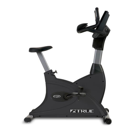
CHAPTER 3: PRODUCT OVERVIEW RECUMBENT BIKE OVERVIEW: Console Assembly Contact Heart Rate Pads Seat Adjustment Knob Pedals Leveling Feet Truefitness.com / 800.426.6570 / 636.272.7100... - Page 19 CHAPTER 3: PRODUCT OVERVIEW RECUMBENT BIKE OVERVIEW (CONTINUED): Console Assembly: The console allows the user to set up a workout program and control the bike during a workout. Contact Heart Rate Pads: Allows the user to check their heart rate without wearing a wireless chest strap. Seat Adjustment Knob: Used to adjust the position of the seat to a comfortable position for the user.
-
Page 20: Chapter 4: Programming & Operation Heart Rate Monitoring
HEART RATE CONTROL (HRC): Introduction: You are now the owner of the most sophisticated Heart Rate Control equipment available. TRUE HRC is unique and patented. It accommodates users from rehabilitation to world class athletes, and all those in between. TRUE HRC allows users to do a completely adjustment free heart rate controlled workout. -
Page 21: Target Heart Rate
HEART RATE CONTROL (continued): The TRUE HRC system is unique because users must enter the key parameters of the workout; target heart rate, weight, age, and time, prior to beginning the HRC workout. As users approach their target heart rate, the bike’s computer takes full control over the workout and changes the workout intensity automatically to keep users near their target heart rate. -
Page 22: Program Descriptions
CHAPTER 4: PROGRAMMING & OPERATION PROGRAM DESCRIPTIONS: Quick Start: A workout in which the user controls all settings. The workout continues until it is ended by the user. Manual: Users s their et up own workout to a TIME or DISTANCE limit. Easy Intervals: 2-minute segments with increased WORKLOAD with a moderate change between segments. - Page 23 Custom Workouts: The CS200 Bikes have 3 types of custom workouts available; Scale, Fixed and Record. Scale: The user sets the workout time and the uses the workload keys to enter up to 60 segments. The bike will automatically scale the segment time to the workout time set by the user.
-
Page 24: Console Overview
CHAPTER 4: PROGRAMMING & OPERATION CONSOLE OVERVIEW: Preset Lower LED Manual Upper LED HRC Cruise Preset Display Workouts Workout Display Control Workouts Change Display Start Enter Numeric Workload Reading Warning Keypad Keys Rack Decal Truefitness.com / 800.426.6570 / 636.272.7100... - Page 25 CHAPTER 4: PROGRAMMING & OPERATION CONSOLE OVERVIEW (continued): Workload Keys: Manually increases or decreases the workout intensity. Start: Allows the user to begin a Quick Start workout or preset workout. Change Display: Toggles the data in the upper LED display between available options. Reading Rack: A ledge on the console that can be used to hold a book, magazine, e-reader, or tablet computer during a workout.
-
Page 26: Console Navigation
CHAPTER 4: PROGRAMMING & OPERATION CONSOLE OVERVIEW (continued): Upper LED Display: Shows the workout data of the program in progress in four value displays. Value Display #1 Value Display #2 Value Display #3 Value Display#4 Calories – an estimate Heart Rate – Beats per Time Remaining –... - Page 27 CHAPTER 4: PROGRAMMING & OPERATION CONSOLE NAVIGATION (continued): Workout Data Entry: Before beginning a preset workout, the console will ask the user for information in order to give more accurate workout data. To adjust the Data Value (A), use the Numeric Keypad (B) or the Up and Down Workload Keys (C).
-
Page 28: Advanced Console Functions
CHAPTER 4: PROGRAMMING & OPERATION ADVANCED CONSOLE FUNCITONS: Entering Setup Mode: Setup mode allows the user to change the default options for the console and allow the unit to be customized to the facility in which it is installed. To enter Setup Mode, press and hold the Clear Entry button (A) until the console beeps. While continuing to hold the Clear Entry button, immediately press and hold the Enter button (B) until “ENTER PASS CODE”... - Page 29 CHAPTER 4: PROGRAMMING & OPERATION ADVANCED CONSOLE FUNCITONS (continued): Entering Maintenance Mode: Maintenance Mode is used to troubleshoot issues and to test console functions. To enter Maintenance Mode, press and hold the Clear Entry button (A) until the console beeps. While continuing to hold the Clear Entry button, immediately press and hold the Enter button (B) until “ENTER PASS CODE”...
-
Page 30: Chapter 5: Care & Maintenance
It is important to perform the minor maintenance tasks described in this section. Failure to maintain the bike as described here could void the TRUE Fitness Warranty. To reduce the risk of electrical shock, always unplug the unit from its power source before cleaning or performing any maintenance tasks. -
Page 31: Leveling The Unit
CHAPTER 5: CARE & MAINTENANCE OTHER SCHEDULED PREVENTIVE MAINTENANCE: TRUE recommends that yearly scheduled maintenance be performed by a qualified service technician. Please contact your dealer or visit www.truefitness.com to contact a local TRUE authorized service technician. Scheduled Preventive Maintenance: •... -
Page 32: Chapter 6: Customer Service
HOURS OF OPERATION: 8:30 A.M. - 5:00 P.M. CST E-MAIL: service@truefitness.com CONTACTING SALES: Interested in TRUE Products? Please contact us with any sales or product inquires so that we may direct you to the appropriate sales representative to answer your questions. TRUE FITNESS HOME OFFICE 865 HOFF ROAD ST. -
Page 33: Reporting Freight Claims Or Parts Damage
Severe Damage: Obvious damage to external packaging / internal product. Please refuse the shipment and it will be returned to TRUE Fitness by the carrier. Contact the TRUE Fitness customer support team by calling 800.883.8783 or sales support team by calling 800.426.6570 Monday-Friday during normal business hours to notify us that the shipment has been refused. -
Page 34: Chapter 7: Additional Information
The angled seat post better accommodates users of all sizes and the handlebar design along with the dual stage drive system will give users a true road bike feel. The compact footprint will help maximize floor space in every fitness center while giving users differing workout intensity levels that suite beginners through advanced users. - Page 35 Contact Heart Rate Monitoring Wireless Heart Rate Monitoring Polar Compatible ® CONSOLE Display Programs HRC Workouts HRC Cruise Control Standard TRUE Speed Fine Control Standard Standard Bike Simulation Fitness Test YMCA Protocol CSAFE Power Standard Diagnostic Standard SAFETY Low Step Over Height...
-
Page 36: Warranty Registration
Save Time and Register Online! Activate Multiple Warranties at www.truefitness.com/support All TRUE® Fitness products are distributed by TRUE and are not warrant the performance of the heart rate system on its warranted to the original registered product purchaser and the products, as the heart rate system performance varies, based parts of the TRUE product (the “Product”) listed below, under... - Page 37 Registration Form is completed on-line; or if the attached form CS200 UPRIGHT BIKE SERIAL NUMBERS: is filled in, signed by the original purchaser and mailed to TRUE within 30 days of purchaser’s receipt of this Product. The serial The CS200 upright bike comes with two serial numbers; one on number must be intact on the Product for this Limited Warranty the base and one on the display console (see diagram below).
- Page 38 CS200 Upright Bike Thank you for purchasing a TRUE product. To validate the TRUE product warranty the fast and easy way, please go on-line now to truefitness.com/support and register your product. The information you provide will never be distributed to any other individuals or agencies for any purpose.
Need help?
Do you have a question about the CS200 and is the answer not in the manual?
Questions and answers