Pfaff 335 Instruction Manual
Hide thumbs
Also See for 335:
- Instruction manual (58 pages) ,
- Adjustment manual (36 pages) ,
- Instruction manual (34 pages)

Related Manuals for Pfaff 335


Summary of Contents for Pfaff 335
-
Page 1: Instruction Manual
Instruction manual This instruction manual applies to machines from the following serial numbers onwards: # 2432978 296-12-18 393/002 Betriebsanleitung engl. 06.05... - Page 2 This Instruction manual is valid for all models and subclasses listed in the chapter "Specifications". The reprinting, copying or translation of PFAFF Instruction Manuals, whether in whole or in part, is only permitted with our previous authorization and with written reference to the source.
-
Page 3: Table Of Contents
Danger .......................... 1 - 4 Proper use ........................2 - 1 Specifications ......................3 - 1 PFAFF 335 ........................3 - 1 Versions and subclasses ....................3 - 1 Disposal of machine ....................4 - 1 Transport, packaging and storage ................5 - 1 Transport to the customer .................... -
Page 4: Contents
Contents Contents ................. Chapter - Page Preparation ........................9 - 1 Inserting the needle ...................... 9 - 1 Winding the bobbin thread, adjusting the thread tension ..........9 - 2 Removing / Inserting the bobbin case ................9 - 3 Threading the bobbin thread and regulating the bobbin thread tension ...... - Page 5 Contents Contents ................. Chapter - Page .05.07 Lateral adjustment of the thread catcher ..............11 - 22 .05.08 Control cam, final adjustment ..................11 - 23 .05.09 Knife ..........................11 - 24 .05.10 Triggering the needle thread tension ................11 - 25 .05.11 Cutting test .........................
-
Page 6: Safety
Safety Safety 1.01 Regulations This machine has been made according to the European regulations indicated in the conformity and manufacturer’s declarations. In addition to this instruction manual, please also observe all generally accepted statutory and other legal requirements, including those of the user’s country, and the valid pollution control regulations! The locally valid regulations of the social insurance institution responsible for occupational accidents, or other supervisory authorities, must be strictly adhered to! General notes on safety... -
Page 7: Safety Symbols
The user must ensure that none of the safety devices are removed nor put out of working order. The user must ensure that only authorized persons operate and work on the machine. For further information please refer to your PFAFF agency. 1- 2... -
Page 8: Notes For Operating And Technical Staff
Safety Notes for operating and technical staff Operating staff 05.01 Operating staff are the persons responsible for setting up, operating and cleaning the machine and for removing any disturbances in the sewing area. The operating staff must be sure to observe the following items: always observe the notes on safety in this instruction manual in their work! refrain from any working methods which adversely effect the safety of the machine! avoid wearing loose clothing or jewelry such as necklaces or rings! - Page 9 Safety Danger symbols A working area of 1 metre is to be kept free both in front of and behind the machine while it is in operation so that it is always easily accessible. Never reach into the sewing area while sewing! Danger of injury by the needle! Never leave objects on the table or in the needle plate area while adjusting the machine settings! Objects can become trapped or be slung away! Danger of...
-
Page 10: Proper Use
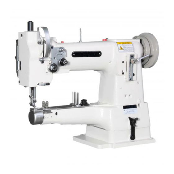
Proper use Proper use The PFAFF 335 is a single needle, free-arm sewing machine with bottom, top and needle feeds for sewing lockstitch seams. Any use of this machine which is not approved by the manufacturer shall be considered as improper use! The manufacturer shall not be held liable for any... -
Page 11: Specifications
Specifications Specifications PFAFF 335 Stitch type: ....................301 ( lockstitch) Model: ..........................B Needle system: ......................134 - 35 Needle thickness (Nm) in 1/100 mm: ................ 80 - 100 Max. stitch length: on sub classes -940/01-6/01 ..................4,5 mm on sub classes -2/27; -6/01; -17/01; -39/21 ..............6,0 mm Handwheel effective dia.: .................. -
Page 12: Disposal Of The Machine
Disposal of the machine Disposal of the machine The proper disposal of the machine is the responsibility of the user. The materials used for the machine are steel, aluminium, brass and various plastics. The electrical equipment consists of plastics and copper. The machine must be disposed of in accordance with applicable local pollution control regulations. -
Page 13: Storage
Transportation, packing and storage Transportation, packing and storage Transport zum Kundenbetrieb Die Maschinen werden komplett verpackt geliefert. Transportation to customer's premises The machines are delivered completely packed. Disposal of packing materials The packing materials of this machine comprise paper, cardboard and VCE fibre. Proper dis- posal of the packing material is the responsibility of the customer. -
Page 14: Explanation Of The Symbols
Explanation of the symbols Explanation of the symbols In this Instruction Manual, work to be carried out and important information are drawn to your attention by symbols. The symbols have the following meanings: Note, information Cleaning, care Lubrication Servicing, repairing, adjustment, maintenance (only to be carried out by specialist personnel) 6 - 1... -
Page 15: Controls
Controls Controls On/off switch Switch the machine on or off by turning main switch 1. The switch in the illustration can be found on machines with Quick motors. When other motors are used, the switch may not look the same. Fig. -
Page 16: Lever For Lifting The Presser Foot
Controls Lever for lifting the presser foot To lift the presser foot, raise lever 1. Fig. 7 - 03 Stitch-length adjustment lever / reverse sewing Adjust the stitch length by turning the milled nut on lever 1 as required. Reverse sewing For reverse sewing, push lever 1 up during sewing. -
Page 17: Adjustment Nut For The Top Feed Lift
Controls Adjustment nut for the top feed lift Switch off the machine! Danger of injury if the machine is started accidentally! Open cover 1 on the back of the machine, loosen nut 1 and move it as required. Fig. 7 - 05 7 - 3... -
Page 18: Mounting And Commissioning The Machine
Mounting and commissioning the machine Mounting and commissioning the machine The machine must only be mounted and commissioned by qualified personnel! All relevant safety regulations are to be observed! If the machine is delivered without a table, be sure that the frame and the table top which you intend to use can hold the weight of the machine and the motor. -
Page 19: Tightening The V-Belt
Mounting and commissioning the machine Tightening the V-belt .01.02 Loosen nuts 1. Tighten the V-belt using the dolly switch 2. Tighten nuts 1. Fig. 8-02 shows a Quick motor. If another motor is used proceed as described in the instruction manual! Fig. -
Page 20: Mounting The Lower V-Belt Guard
Mounting and commissioning the machine Mounting the lower V-belt guard .01.04 Align the V-belt guard 7 in such a way that both the motor pulley and the V-belt run freely. Tighten screws 8. Fig. 8-04 shows a Quick motor. If another motor is used proceed as described in the instruction manual! -
Page 21: Fitting The Synchronizer
Mounting and commissioning the machine Fitting the synchronizer .01.06 Slide synchronizer 1 onto the shaft, so that the position stop 2 is positioned in the groove of the synchronizer (see arrow). Tighten screws 3. Connect and adjust synchronizer 1 (see Motor Instruction Manual and Chapter 11.05.12 Adjusting the synchronizer). -
Page 22: Table Top Cutout
Mounting and commissioning the machine Table top cutout 8 - 5... -
Page 23: Preparation
Setting up Preparation All regulations and instructions in this Instruction Manual are to be observed! Special attention is to be paid to the safety regulations! All preparation work is only to be carried out by appropriately trained personnel. Before all preparation work, the machine is to be separated from the electricity supply by removing the plug from the mains or switching off the On/Off switch! Inserting the needle Switch off the machine! -
Page 24: Winding The Bobbin Thread, Adjusting The Thread Tension
Setting up Winding the bobbin thread, adjusting the thread tension Fig. 9 - 02 Place an empty bobbin 1 onto bobbin shaft 2. Thread the bobbin in accordance with Fig. 9-02 and wind it anti-clockwise around bobbin 1 a few times. Switch on the bobbin winder while at the same time pressing bobbin winder spindle 2 and lever 3. -
Page 25: Removing / Inserting The Bobbin Case
Setting up Removing / Inserting the bobbin case Switch off the machine! Danger of injury due to unintentional starting of the machine! Removing the bobbin case: Lift latch 1 and take out bobbin case 2. Inserting the bobbin case: Insert full bobbin case 2 so that you feel it snap in place. -
Page 26: Threading Needle Thread/Adjusting Needle Thread Tension
Setting up Threading needle thread/adjusting needle thread tension Fig. 9 - 05 Switch off the machine! Danger of injury due to unintentional starting of the machine! Thread needle thread as shown in Fig. 9-05. Be sure to thread the needle from the left. Regulate the needle thread tension by turning knurled screw 1. -
Page 27: Care And Maintenance
Care and maintenance Care and maintenance Care and maintenance intervals Cleaning ............daily, in continuous operation several times General oiling ....................twice a week Oil the hook ..............daily, before putting into operation Oil needle-head parts ..................twice a week Lubricate the bevel gears .................. -
Page 28: General Oiling
Tighten screw 1 again. Only use oil with a viscosity of 22.0 mm /s at 40° C and a density of 0.865 g/cm at 15°C! We recommend PFAFF sewing- machine oil, part No. 280-1-120144. Fig. 10 - 03 10 - 2... -
Page 29: Oiling The Sewing Hook
Only use oil with a viscosity of 22.0 mm /s at 40° C and a density of 0.865 g/cm at 15°C! We recommend PFAFF sewing- machine oil, part No. 280-1-120144. Fig. 10 - 04 Oiling the needle-head parts Switch off the machine! -
Page 30: Lubricating The Bevel Gears
Use both hands to set the sewing head upright! Danger of crushing between the sewing head and the table top! Retighten screw 2. We recommend PFAFF sodium grease with a dripping point of approx. 150C, Order No. 280-1-120 243. 10 - 4... -
Page 31: Checking/Adjusting The Air Pressure
Care and maintenance Checking/adjusting the air pressure Before operating the machine, always check the air pressure on gauge1. Gauge 1 must show a pressure of 6 bar. If necessary adjust to this reading. To do so, pull knob 2 upwards and turn it so that the gauge shows a pressure of 6 bar. -
Page 32: Adjustment
Adjustment Adjustment Unless stated otherwise, during all adjustment work the machine must be disconnected from the electric and pneumatic power supply! Danger of injury if the machine is started accidentally! Notes on adjustment All following adjustments are based on a fully assembled machine and may only be carried out by expert staff trained for this purpose. -
Page 33: Adjusting The Basic Machine
Adjustment Adjusting the basic machine Lateral positioning of the feed dog 04.01 Requirement The clearances from the left and right of the bottom feed dog 1 to the needle plate cutout must be the the same size. X = X Fig. -
Page 34: Lengthwise Positioning Of The Feed Dog
Adjustment Lengthwise positioning of the feed dog .04.02 Requirement With the stitch length set at its longest the clearances behind and in front of the bottom feed dog 5 to the needle plate cutout must be the same. Fig. 11 - 02 Set the longest stitch length. -
Page 35: Height Of The Bottom Feed Dog (Only On Machines With Lifting Phase - P-Version)
Adjustment Height of the bottom .04.03 feed dog (only on machines with lifting phase – P-version) Requirement When the stitch length is set at „0“ , in its highest position the bottom feed dog 4 should be 0.8 – 1.1 mm above the top edge of the needle plate. 0,8 - 1,1 mm Fig. -
Page 36: Centering The Needle In The Needle Hole
Adjustment Centering the needle in the needle hole 04.04 Requirement With the stitch length set at “0“ the needle must enter the needle hole exactly in the middle. Fig. 11 - 04 Unscrew the vibrating presser foot 1 and the presser foot 2. Set the stitch length at “0“... -
Page 37: Pre-Adjusting The Needle Height
Adjustment Pre-adjusting the needle height .04.05 Requirement With the needle bar at its bdc the distance between the needle bar and the needle plate must be 15 mm. 15 mm Fig. 11 - 05 Move the needle bar 1 (screw 2) in accordance with the requirement without twisting it. 11 - 6... -
Page 38: Driving Motion Of The Top And Bottom Feed Dogs
Adjustment Driving motion of the top and bottom feed dogs 04.06 Requirement With the longest stitch length set and the needle bar at its bdc the top and bottom feed dogs should not move when the reverse feed lever is activated. Fig. -
Page 39: Lifting Motion Of The Bottom Feed Dog (Only On Machines With Lifting Phase - P-Version)
Adjustment Lifting motion of the bottom feed dog 04.07 (only on machines with lifting phase – P-version) Requirement 1. With the needle bar positioned at b.d.c., the bottom feed doc should be in the t.d.c. position. 2. With the maximum stitch length set, when the balance wheel is turned the bottom feed dog should reach the needle plate surface at the same time as the needle point. -
Page 40: Needle Rise, Hook-To-Needle Clearance And Needle Height
Adjustment Needle rise, hook-to-needle clearance and needle height 04.08 Requirement With the stitch length set at “0“ (1.8 mm after the bdc of the needle bar) the following must be correct: 1. The hook point must be opposite the middle of the needle and the distance to the needle must be 0.05 - 0.1 mm. -
Page 41: Vibrating Presser Lift
Adjustment Vibrating presser lift 04.09 Requirement With the vibrating presser lift at maximum and the stitch length set at “0“ , presser foot 1 and vibrating presser foot 2 must lift 7.0 mm from the needle plate when the handwheel is rotated. -
Page 42: Vibrating Presser Feeding Motion
Adjustment Vibrating presser feeding motion 04.10 Requirement With the presser foot 3 resting on the needle plate the vibrating presser 6 and the needle point must both reach the needle plate at the same time with the vibrating presser stroke at maximum. -
Page 43: Needle Thread Tension Release
Adjustment Needle thread tension release 04.11 Requirement With the presser foot lifted, the two tension disks must be at least 0.5 mm apart. The distance of 0.5 mm is the minimum clearance. The clearance can range up to more than 1 mm with thick threads. 0,5 mm Fig. -
Page 44: Thread Check Spring
Adjustment Thread check spring 04.12 Requirement The movement of the thread check spring must be finished when the needle point enters the material (= approx. 7 mm spring movement). The length of the spring movement can vary a little upwards or downwards due to changes in the sewing parameters. -
Page 45: Bobbin Winder
Adjustment Bobbin winder 04.13 Requirement 1. With the bobbin winder engaged the winder spindle must be driven reliably. With the bobbin winder disengaged, however, the friction wheel 5 must not touch the drive wheel 1. 2. The bobbin winder must stop automatically when the thread wound on the bobbin has reached a point approx. -
Page 46: Regulating The Pressure On The Presser Foot
Adjustment Regulating the pressure on the presser foot 04.14 Requirement The material must be fed perfectly even at top sewing speed. There must not be any pressure marks on the material. Fig. 11 - 14 Turn screw 1 in accordance with the requirement. 11 - 15... -
Page 47: Adjusting The Thread Trimmer -900/52 (Optional)
Adjustment Adjusting the thread trimmer -900/52 (optional) Preadjusting the control cam 05.01 Requirement With the take-up lever at its bdc, projection 4 on the control cam 2 must be directly underneath the cam follower 5. Fig. 11 - 15 Loosen the two screws on the control cam 2 through the assembly hole 1. Bring the take-up lever to its bdc by turning the handwheel . -
Page 48: Tripping Lever Height
Adjustment Tripping lever height 05.02 Requirement With the needle bar at its bdc there must be a distance of 1.0 mm between the tripping lever 3 and the control cam 4. 1 mm Fig. 11 - 16 Bring the needle bar to its bdc by turning the handwheel. Move the carrier 1 (screws 2) of the tripping lever 3 in the elongated hole in accordance with the requirement. -
Page 49: Feed Regulator Pin
Adjustment Feed regulator pin 05.03 Requirement With the needle bar at its bdc, the feed regulator pin 5 must be able to fall lightly into the path of the control cam 7 when the engaging solenoid 6 is activated. Fig. 11 - 17 Bring the needle bar to its bdc by turning the handwheel. -
Page 50: Engaging Solenoid
Adjustment Engaging solenoid 05.04 Requirement With the needle bar at its bdc and with the magnet core 1 fully activated, there must be a clearance of approx. 0.5 mm between the pawl 7 and the retaining collar 6. 0,5 mm Fig. -
Page 51: Adjusting The Height Of The Feed Regulator Pin
Adjustment Adjusting the height of the feed regulator pin 05.05 Requirement With the thread trimmer in resting position and the pawl 4 clicked in place there must be a clearance of 0.3 mm between the highest point of the control cam 5 and the feed regulator pin. -
Page 52: Thread Catcher, Front Point Of Reversal
Adjustment Thread catcher, front point of reversal 05.06 Requirement With the thread catcher 3 at its front point of reversal, the rear edge of the thread catcher cutout must still be 1 mm over the front edge of the bobbin case position-finger 6. 1 mm Fig. -
Page 53: Lateral Adjustment Of The Thread Catcher
Adjustment Lateral adjustment of the thread catcher 05.07 Requirement With the needle bar at its bdc, the tip of the thread catcher 3 must point exactly at the middle of the needle. Fig. 11 - 21 Remove knife 1 (screws 2). Bring the needle bar to its bdc by turning the handwheel. -
Page 54: Control Cam, Final Adjustment
Adjustment Control cam, final adjustment 05.08 Requirement With the end of the thread guard 2 mm behind the middle of the bobbin case position- finger 3, the clearance between the thread catcher point 4 and the thread guard 2 must be approx. -
Page 55: Knife
Adjustment Knife 05.09 Requirement With the left edge of the thread catcher notch 1 mm in front of the knife edge, the left knife edge must be flush with the edge of the thread catcher (see arrow in circle). Fig. 11 - 23 Loosen screws 2 on knife 1. -
Page 56: Triggering The Needle Thread Tension
Adjustment Triggering the needle thread tension 05.10 Requirement With the tip of the release lever 5 at the highest point of the tension release cam 4, the tension disks must be at least 5 mm apart. 0,5 mm Fig. 11 - 24 Bring the sewing foot to rest on the needle plate using the hand lever. -
Page 57: Cutting Test
Adjustment Cutting test 05.11 Requirement Both threads must be trimmed perfectly. Fig. 11 - 25 Bring the needle bar to its bdc by turning the handwheel and activate the magnet core 1. Turn the handwheel in its direction of rotation until the thread catcher 2 is at its front point of reversal. -
Page 58: Positioner
Adjustment Positioner 05.12 Requirement When interrupting the sewing procedure the machine must position itself at 4 mm after the bdc of the needle bar. After trimming the thread, the machine must position itself at the tdc of the take-up lever. Carry out the adjustment in accordance with the instruction manual of the motor. -
Page 59: Wearing Parts
This is a list of the most important wearing parts. A detailed parts list for the complete machine can be downloaded from the internet address www.pfaff-industrial.com/de/service/download/index.php3. As an alternative to the internet download, the parts list can also be ordered as a book under No. - Page 60 Wearing parts 99-137 151-45 91-171 049-05 91-171 042-05 PFAFF 335-900/52 91-000 094-25 (2x) 91-165 505-05 91-014 046-05 11-108 084-15 (2x) 91-000 452-15 (2x) 91-010 023-05 12 - 2...
- Page 61 Notes...
- Page 62 PFAFF Industrie Maschinen AG Postfach 3020 D-67653 Kaiserslautern Königstr. 154 D-67655 Kaiserslautern Telefon: (0631) 200-0 Telefax: (0631) 17202 E-Mail: info@pfaff-industrial.com...