Friedrich CP10 Service & Parts Manual
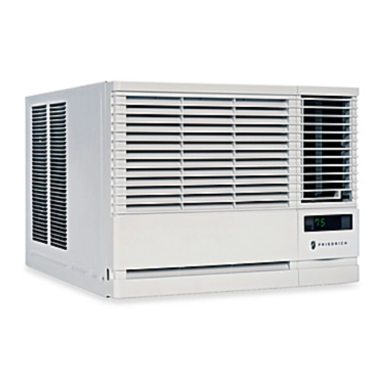
Room air conditioner chill 115 volts
Hide thumbs
Also See for CP10:
- Installation and operation manual (64 pages) ,
- Installation & operation manual (64 pages) ,
- Installating and operation manual (61 pages)

Related Manuals for Friedrich CP10


Summary of Contents for Friedrich CP10
-
Page 1: Room Air Conditioner
Room Air Conditioner Service & Parts Manual 2014-2015 CP10 & CP12 Chill 115 Volts THE EXPERTS IN ROOM AIR CONDITIONING 93011402_04... -
Page 2: Table Of Contents
CONTENTS 1. PREFACE 2.4 REFRIGERATION CYCLE.........9 2.4.1 CONDENSER ........9 1.1 SAFETY PRECAUTIONS .......2 2.4.2 EVAPORATOR ........9 1.2 INSULATION RESISTANCE TEST....2 2.4.3 CAPILLARY TUBE.......9 1.3 PRODUCT SPECIFICATIONS .......3 3. SCHEMATIC DIAGRAM 1.4 OPERATING INSTRUCTIONS.......4 3.1 CIRCUIT DIAGRAM ........12 2. DISASSEMBLY INSTRUCTIONS 4. -
Page 3: Product Specifications
1.3 PRODUCT SPECIFICATIONS Buyer Model CP12G10A CP10G10A PERFORMANCE BTU performance (Cooling) 10,000 12000 BTU performance (Heating) 11.3 11.3 Dehumid. ( Pts/Hr) Dry Air Flow (CFM) 53/58 53/58 dBA Level (Indoor / Outdoor) Est. Cooling Area (SQ.FT) Electrical Ratings Voltage / 60 Hz 1060 Watts (Cooling) Watts (Heating) -
Page 4: Operating Instructions
1.4 OPERATING INSTRUCTIONS MoneySaver: The fan will stop when the compressor stops cooling. The fan will turn on approximately every 3 minutes to sample to room air and determine if more cooling is needed. Cool: fan runs continually for normal cooling operation Fan Only: Fan-only operation *MoneySaver has it’s own button on your remote control... -
Page 5: Disassembly Instructions
2. DISASSEMBLY INSTRUCTIONS — Before the following disassembly, POWER SWITCH is set to OFF and disconnected the power cord. 2.1 MECHANICAL STRUCTURE 2.1.1 FRONT GRILLE 1. Open the lnlet grille upward or downward. 2. Remove the screw which fastens the front grille. 3. -
Page 6: Air Handling Parts
Air handling parts 2.2 AIR HANDLING PARTS 2.2.1. AIR GUIDE AND BL OWER 1. Remove the front grille. 2. Remove the cabinet. 3. Remove the control box. 4. Remove the 3 screws which fasten the brace. 5. Remove the brace. 6. -
Page 7: Motor
2.2.3. MOTOR 1. Remove the cabinet. 2. Remove the evaporator. 3. Remove the orifice. 4. Remove the blower. 5. Remove the fan. 6. Remove the control box cover and housing of the motor in the control box. 7. Remove the 2 screws which fasten the motor from the mount motor. -
Page 8: Capacitor
2.3.3. CAPACITOR 1. Remove the control box. 2. Remove the screw which fasten control panel from control box. 3. Remove the screw which located in the front. 4. Open the bottom side of control box. 5. Remove the screw and the clamp which fastens the capacitor. -
Page 9: Refrigeration Cycle
2.4 REFRIGERATION CYCLE CAUTION: Discharge the refrigerant system using Freon Recovery System.If there is no valve to attach the recovery system, install one (such as a WATCO A-1) before venting the Freon . Leave the valve in place after servicing the system. 2.4.1 CONDENSER 1. - Page 10 NOTICE remaining in the system. With valves A and B closed, stop the vacuum pump. -Replacement of the refrigeration circuit. 4) Remove the hose from the vacuum pump and 1. When replacing the refrigeration circuit, be sure to place it on the charging cylinder. See figure Discharge the refrigerant system using a Freon 37B.
- Page 11 Equipment needed: Vacuum pump, Charging cylinder, Manifold gauge, Brazing equipment. Pin-off tool capable of making a vapor-proof seal, Leak detector, Tubing cutter, Hand Tools to remove components, Service valve. Figure 33B-Charging Figure 33A-Pulling Vacuum —11—...
-
Page 12: Schematic Diagram
3. SCHEMATIC DIAGRAM 3.1 CIRCUIT DIAGRAM Pressure Switch (SMPS) 250V/T3.15A PN:MEZ65238803 Fault Codes Error No. Error Item Error Content Indoor air sensor open or short CH01 Indoor Air Sensor Error EEPROM reading date error CH09 EEPROM CheckSum Error CH34 High Pressure Error As high pressure,comp off over 10 times in 1 hour. -
Page 13: Piping System
4. TROUBLESHOOTING GUIDE 4.1 PIPING SYSTEM CONDENSER COIL CAPILLARY TUBE MOTOR COMPRESSOR BLOWER EVAPORATOR COIL Figure 32 is a brief description of the important components and their function in what is called the refrigeration system. This will help you to understand the refrigeration cycle and the flow of the refrigerant in the cooling cycle. ROOM AIR CONITIONER CYCLE OF REFRIGERATION EVAPORATOR COILS... -
Page 14: Troubleshooting Guide
4.2 TROUBLESHOOTING GUIDE In general, possible trouble is classified in two causes. The one is called Starting Failure which is caused from an electrical defect, and the other is Ineffective Air Conditioning caused by a defect in the refrigeration circuit and improper application. Unit is running but cooling is ineffective Ineffective Cooling Check of cold air circulation... - Page 15 Fails to Start Check of power source. Check of circuit breaker and fuse. Check of control switch Gas leakage of feeler bulb setting. of thermostat Check of control switch. Only compressor fails to Only fan fails to start. start. Improper wiring. Drop of power voltage.
- Page 16 COMPLAINT CAUSE REMEDY Fan motor will not run. No power Check voltage at outlet. Correct if none. Power supply cord Check voltage to rotary switch. If none, check power supply cord. Replace cord if circuit is open. Rotary switch Check switch continuity. Refer to wiring diagram for terminal identification.
-
Page 17: Room Air Conditioner Voltage Limits
COMPLAINT CAUSE REMEDY Compressor will not run, Voltage Check voltage. See the limits on the preceding. but fan motor runs. page. If not within limits, call an electrician. Wiring Check the wire connections, if loose, repair or replace the terminal. If wires are off, refer to wiring diagram for identification, and replace. - Page 18 REMEDY COMPLAINT CAUSE Compressor cycles Voltage Check the voltage. See the limits on the preced- on overload. ing page. If not within limits, call an electrician. Overload Check overload, if externally mounted. Replace if open. (If the compressor temperature is high, remove the overload, cool, and retest.) Fan motor If not running, determine the cause.
-
Page 19: Exploded View
5.Exploded View CP10G10A 738900 130910 554030 749740 731273 148000 359011 346811 352380 W48602 349600 422100 149980 359012 267110 354210 W48602 349001 349480 567502 147582 135312 130410 554160 152302 550140 135303 249950 W0CZZ 567480 552102 552113 235500 268711-1 238310 352113 146812 147581 264110 35211A... - Page 20 CP12G10A 738900 130910 554030 749740 731273 148000 359011 346811 352380 W48602 349600 422100 149980 359012 267110 354210 W48602 349001 349480 567502 147582 135312 130410 554160 152302 550140 135303 552102-2 552113-2 249950 W0CZZ 567480 552102-1 552113-1 235500 268711-1 238310 352113 146812 147581 264110 35211A...
-
Page 21: Serviceparts List
REF # DESCRIPTION PART NO# NOTES 130410 BASE PAN 67305537 352380 GUIDE ASSEMBLY AIR 67302737 352380 GUIDE ASSEMBLY AIR 67302760 349001 DAMPER VENT 67303508 147582 VERTICAL LOOVER 67306265 349600 MOTOR BRACKET 67303607 346811 FAN MOTOR AC 67303039 346811 FAN MOTOR AC 67303040 359012 FAN, TURBO EVAP... - Page 22 CP10 - CP12 (06/14) 93011402_04...
Need help?
Do you have a question about the CP10 and is the answer not in the manual?
Questions and answers