Advertisement
Quick Links
SMART
One way, two way
Monofamiliari e Bifamiliari
Norme Tecniche
Owner's Manual
Factory - Office
VIDEX ELECTRONICS S.p.A. Via del lavoro,1 63020 MONTEGIBERTO (AP) - ITALY
Phone: (+39) 0734 - 631669 Fax: (+39) 0734 - 632475 www.videx.it e-mail: info@videx.it
SERIES VIDEOKITS
VIDEOKIT SERIE
SMART
We recommend
This equipment is installed by a
Competent Electrician, Security or
Communications Engineer
Advertisement

Related Manuals for Videx SMVK1


Summary of Contents for Videx SMVK1
- Page 1 We recommend This equipment is installed by a Competent Electrician, Security or Communications Engineer Factory - Office VIDEX ELECTRONICS S.p.A. Via del lavoro,1 63020 MONTEGIBERTO (AP) - ITALY Phone: (+39) 0734 - 631669 Fax: (+39) 0734 - 632475 www.videx.it e-mail: info@videx.it...
- Page 2 SMVK1, SMVK1/MV, CSMVK1 Easy Videokit B&W, con MEMORIA VIDEO, a COLORI SMVK1, SMVK1/MV, CSMVK1 Easy Videokit B&W, with MEMORY BOARD, COLOUR I videokit SMVK1 sono forniti con i videocitofoni della The new videokit SMVK1 is supplied with the 3000 series serie 3000 ed il posto esterno Art.331K.
- Page 3 COLLEGAMENTO ALLA RETE ELETTRICA ED CONNECTION TO MAINS AND INSTALLAZIONE DELL’ALIMENTATORE POWER SUPPLY MOUNTING INSTRUCTIONS La realizzazione dell’impianto deve essere eseguita nel rispetto delle vigenti The system must be installed according to national rules in force, in particular normative nazionali, in particolare si raccomanda di: we recommend to: ·...
- Page 4 Fig.9 Fig.10 Art.3351, 3451, 3551 Istruzioni di montaggio per i Videocitofoni Art.3351, 3451 e 3551 Videophones Mounting Instructions Piastra di fissaggio Videocitofono Mounting Plate Applicazione a muro della piastra di Mounting plate installation and PCB Quote in cm fissaggio e collegamenti scheda di connections.
- Page 5 SEGNALI SIGNALS Tabella 1 indica i segnali (e le relative denominazioni) presenti sulla Table 1 shows the videophones Art.3351,3451,3551 connections (and morsettiera della scheda di connessione Art.3980 per i videocitofoni signal name) relevant to the terminals of the PCB connection Art.3980 . Art.3351, 3451 e 3551.
-
Page 6: Collaudo Impianto
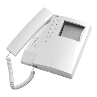
COLLAUDO IMPIANTO SYSTEM TESTING Eseguire tutti i collegamenti secondo gli schemi proposti. Carry out connections accurately using the wiring diagram provided. Verificare la corretta esecuzione delle connessioni e dare tensione all’ Be sure that all connections are well made and then power up the system. impianto. - Page 7 SCHEMA DI INSTALLAZIONE SMVK1 CSMVK-1 WIRING DIAGRAM SMVK1 CSMVK1 Videokit Bianco & Nero e a Colori Videokit B&W or Colour VIDEOCITOFONO: ART.3351 OR 3451 VIDEOPHONE: ART.3351 OR 3451 Cornetta. Handset. Schermo. Screen. Tasto Apriporta. Door Opening Button. Tasto Autoaccensione. Video Recall Button.
- Page 8 WIRING DIAGRAM SMKV1/MV SCHEMA DI INSTALLAZIONE SMVK1/MV Videokit with memory board Videokit con memoria video SCHEMA DI INSTALLAZIONE SMVK1, WIRING DIAGRAM SMVK1, CSMVK1 CSMVK1 con ingresso addizionale plus additional outdoor station Lo schema mostra come realizzare un impianto a 2 ingressi e come collegare un The diagram below shows a 2 entrance video entry system with an additional ·...
- Page 9 ACCESSORI ACCESSORIES È possibile collegare altri videocitofoni in parallelo (Max 3) a quello in Two more videophones can be connected in parallel (max 3) to the one dotazione, come mostrato dallo schema sottostante. Ciascun videocitofono provided, by making the connections described; every additional addizionale necessita di un trasformatore di alimentazione Art.850K.
- Page 10 UTILIZZO DEI PULSANTI DI SERVIZIO HOW TO USE THE SERVICE PUSH BUTTONS Lo schema sottostante mostra alcuni esempi delle funzioni The diagram below shows some samples of using the ·· S1 ·· che è possibile eseguire tramite i pulsanti di servizio “ ” “ ”...
- Page 11 SCHEMA DI INSTALLAZIONE SMVK2, WIRING DIAGRAM SMVK2, CSMVK2 CSMVK2 con ingresso addizionale plus additional outdoor station Lo schema mostra come realizzare un impianto a 2 ingressi The diagram below shows a 2 entrance video entry system · partendo da un kit bifamiliare. Per l’“auto-accensione” made starting from a two way videokit.
- Page 12 Factory - Office VIDEX ELECTRONICS S.p.A. Via del lavoro,1 63020 MONTEGIBERTO (AP) - ITALY Phone: (+39) 0734 - 631669 Fax: (+39) 0734 - 632475 www.videx.it e-mail: info@videx.it Main UK office Northern UK office Danish office...
Need help?
Do you have a question about the SMVK1 and is the answer not in the manual?
Questions and answers