
Subscribe to Our Youtube Channel
Related Manuals for COP-USA CD55NVT


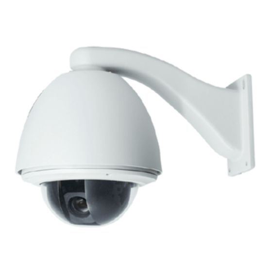
Summary of Contents for COP-USA CD55NVT
- Page 1 HIGH SPEED DOME OPERATION MANUAL PDF created with pdfFactory Pro trial version www.pdffactory.com...
-
Page 2: Table Of Contents
TABLE OF CONTENT 1. Notice---------------------------------------------------------------------------------------------------------1 2. Performance------------------------------------------------------- ------------ ---------------------2 2.1 Speed dome t echnology parameter ------------ -------- -------------- ---------------------------------- 2.2 Camera parameter----------- ----------------------------------------- - ------------------------------ 2.3 Performance & Feature ----------- -------------------------------------- ----- --------------------------------- Function and operation instructio n ---------------------------------------------------------------------------------4 Se t camera ID --------------- --------------------- ------------... - Page 3 5.8.2 W hite balanc e mode ---------- ---------------- ----- ---------------------------------------- Functi on setting -------------------------------- ------------ ------------ --------------------------------- Preset ------------- --------------- ------- ------- ---------------------------------------------------- Scan -------------- --------------------------------- ------- --------------------------------------------- Pattern ---------------- --------------------------- --------- -------------------------------------------- 6.4 Tour------------ --------------------- ------- -- ------------ ----------------------------------------- Zone ---------------- ----------------------------...
- Page 4 Precaution 1. Precaution Ø Electrical safety Conform to country and local electrical safety standard when using or installing the product. Ø Transportation The dome should be protected against extremes of pressure, vibration and humidity during storage installation and transportation. It should be shipped in parts disassembled as the original packing did during the transportation .
-
Page 5: Performance
Performance 2. 1 Technology parameter El ectrical: Setting: ( ) 2400/4800/9600/19200bps AC 24V Power supply Baud rate RS485 、 、 、 Pelc o Ka latel P hlips Diam ond, an d , Indoor10W out door45W Protocol Consumption seve nteen p rotoco ls, etc. Decoder B uilt-in Address setting... -
Page 6: Performance & Feature
Performance 2. 3 Performance and feature A series of intelligent high speed dome is latest design with AMP electrical outlet, built-in constant device, convenient installation, and black cover which make an invisible surveillance. The camera rotates smartly with little noise, and has all kinds of functions, in order to supply perfect image to customer. Ø... -
Page 7: Auto-Run Motion
Function Instruction 3. Function Instruction This passage mainly describes the main function and general principle of integrative speed dome, and does not refer to the concrete operation methods. Different system platform has different operation methods, generally, we should according to the system manufactory's operation manual. Please contact dealer to get necessary information, under some conditions there are have some particular requirements and operations. -
Page 8: Camera Control
Function Instruction Ø Time running “ ” By the menu Time running ,user may set time running function everyday, and set different four actions in four different time in one day, including preset, scan, pattern and tour. 3. 3 Camera control Ø... -
Page 9: Function Instruction
Function Instruction Ø Tour Auto tour is the built-in function in the speed dome, is to make preset arranged in needful order in tour queue by programming in advance. To make camera tour between presets by inserting presets in cruise tour. It is feasible to program tour order, each time as you run tour, you can set the park time of preset A tour can store 24 presets. -
Page 10: System Setting
System Setting 4. System setting 4. 1 Basic operation 4. 1. 1 Current-carrying to dome and Self-testing The dome conducts self-testing after current-carrying , and it rotates slowly until displaying pan origin that is default setting, then moving to tilt origin, the lens is adjusted from far zoom to near zoom, then from near zoom to far zoom, when self-testing is finished, there is relevant system information displaying on the screen, as follow: S/N of the dome... -
Page 11: Edit Dome Label
System setting 4. 2 Edit dome label MAIN MENU ’ When using a lot of domes systems, in order to identify each dome, SYSTEM SETTING : the systems support title setting. The setting ways as follow CAMERA SETTING FUNCTION SETTING 、... -
Page 12: Display Initial Information
System Setting 4. 3 Display initial information MAIN MENU SYSTEM SETTING 、 The system enters into the main menu by calling 95 preset or by calling CAMERA SETTING 9 preset twice within 3 seconds. FUNCTION SETTING WINDOW BLANKING 【 】 【... - Page 13 System setting 4. 4 Display setup MAIN MENU 、 1 The system enters into the main menu by calling 95 preset or by calling SYSTEM SETTING 9 preset twice within 3 seconds. CAMERA SETTING FUNCTION SETTING 、 【 】 【 】...
-
Page 14: Auto Flip
System Setting 4. 5 Systematic motion control MAIN MENU Systematic motion controlling may control a series of canonical mov- SYSTEM SETTING ement of the dome, and plays an important role in controlling the image of CAMERA SETTING the dome. FUNCTION SETTING WINDOW BLANKING The system enters into the main menu by calling 95 preset or by calling ALARMS... -
Page 15: Park Action
System setting 4. 5. 3 Park action MOTION This setting allows the dome to run an appointed action after it enters vacancy for a few time (1-240minutes). If default sets as 0, it means not to AUTO FLIP run this action. PROPORTION PAN PARK TIME 、... -
Page 16: Advance Setting
System Setting 4.5.6 Advance setting MOTION 1.Operate joystick and move to [ADVANCE SETTING], press [OPEN] AUTO FLIP to enter into advance setting; PROPORTION PAN PARK TIME [EIS ENABLED]: Electronic Image Stabilizer function; PARK ACTION SCAN1 POWER UP ACTION AUTO [PRESET FREEZE]: Freeze preset function, namely freezing the FAN ENABLED preset picture transposition function. -
Page 17: Clear
System setting 4. 6 Clear and restart MAIN MENU 、 The system enters into the main menu by calling 95 preset or by calling SYSTEM SETTING 9 preset twice within 3 seconds. CAMERA SETTING FUNCTION SETTING 、 【 】 【 】... -
Page 18: Dome Address
System Setting 4.7 Password set MAIN MENU 1. Call 95 preset or call 9 preset twice within 3 seconds and then input the SYSTEM SETTING password to enter the main menu. CAMERA SETTING FUNCTION SETTING 【 2. Operate the joystick up and down, move the cursor to SYSTEM WINDOW BLANKING 】... - Page 19 System setting 4.8 Time set MAIN MENU 1. Call 95 preset or call 9 preset twice within 3 seconds and then input the SYSTEM SETTING password to enter into the main menu. CAMERA SETTING FUNCTION SETTING 【 2. Operate the joystick up and down, move the cursor to SYSTEM WINDOW BLANKING 】...
- Page 20 System Setting 4.9 Dome Address Setting MAIN MENU 1.Call 95 preset or call 9 preset twice within 3 seconds, to enter into SYSTEM SETTING main menu. CAMERA SETTING FUNCTION SETTING 【 2.Tilt up/down the joystick and move the cursor to SYSTEM WINDOW BLANKING 】...
-
Page 21: Camera Setting
Camera setting 5. Camera setting MAIN MENU 5. 1 Zoom speed SYSTEM SETTING CAMERA SETTING 、 The system enters into the main menu by calling 95 preset or by calling 9 FUNCTION SETTING preset twice within 3 seconds. WINDOW BLANKING ALARMS EXIT 、... -
Page 22: Digital Zoom Control
Camera Setting 5. 2 Digital zoom control MAIN MENU 、 The system enters into the main menu by calling 95 preset or by calling SYSTEM SETTING 9 preset twice within 3 seconds. CAMERA SETTING FUNCTION SETTING 、 【 】 【 】... -
Page 23: Back Light Compensation
Camera setting 5. 3 Back light compensation MAIN MENU 、 The system enters into the main menu by calling 95 preset or by calling 9 SYSTEM SETTING preset twice within 3 seconds. CAMERA SETTING FUNCTION SETTING 、 【 】 Operate joystick, move the cursor to CAMERA SETTING to enter WINDOW BLANKING... -
Page 24: Slow Shutter
Camera Setting 5. 4 Slow shutter control MAIN MENU 、 The system enters into the main menu by calling 95 preset or by calling SYSTEM SETTING 9 preset twice within 3 seconds. CAMERA SETTING FUNCTION SETTING 、 【 】 Operate joystick, move the cursor to CAMERA SETTING to enter WINDOW BLANKING ALARMS... -
Page 25: Line Sync Control
Camera setting 5. 5 Line sync control MAIN MENU SYSTEM SETTING 、 The system enters into the main menu by calling 95 preset or by calling CAMERA SETTING 9 preset twice within 3 seconds. FUNCTION SETTING WINDOW BLANKING 、 【 】... -
Page 26: Ir Cut Filter
Camera Setting 5. 7 IR cut filter MAIN MENU 、 The system enters into the main menu by calling 95 preset or by SYSTEM SETTING calling 9 preset twice within 3 seconds. CAMERA SETTING FUNCTION SETTING 、 【 】 Operate joystick, move the cursor to CAMERA SETTING WINDOW BLANKING enter submenu. -
Page 27: Advance Setting
Camera setting 5. 8 Advance setting MAIN MENU SYSTEM SETTING 、 The system enters into the main menu by calling 95 preset or by calling CAMERA SETTING 9 preset twice within 3 seconds. FUNCTION SETTING 、 【 】 WINDOW BLANKING Operate joystick, move the cursor to CAMERA SETTING to enter... -
Page 28: White Balance Mode
Camera Setting 5. 8. 2 White balance mode MAIN MENU 【 】 、 【 】 、 System supports AUTO indoor mode INDOOR outdoor SYSTEM SETTING 【 】 、 【 】 、 【 】 、 mode OUTDOOR auto track mode single mode CAMERA SETTING 【... -
Page 29: Function Setting
Function setting 6. Function setting MAIN MENU 6. 1 Preset SYSTEM SETTING 、 The system enters into the main menu by calling 95 preset or by calling CAMERA SETTING “ 9 preset twice within 3 seconds. Click each command to enter preset m- ”... -
Page 30: Auto Tracking
Function setting 6. 2 Scan MAIN MENU Scan is that pre-set two points , then the camera repeatedly scan betw- SYSTEM SETTING een the two points at a stable speed, the same magnification and pan. A do- CAMERA SETTING me has four scan tour. FUNCTION SETTING 、... - Page 31 Function setting 6. 3 Pattern MAIN MENU Pattern is built-in function in camera; the speed dome can record tracks SYSTEM SETTING that are no less than 180s. (A series of pan/tilt controlling and lens control- CAMERA SETTING ling command). A dome may set up to 4 pattern tours. FUNCTION SETTING 、...
- Page 32 Function setting MAIN MENU 6. 4 Tour SYSTEM SETTING Tour is the built-in function in the speed dome, it will arrange the pres- CAMERA SETTING ets into the queue of auto-tour, and can set how long it will park at preset. FUNCTION SETTING Operate auto-tour is a process of incessantly transfer each preset.
- Page 33 Function setting 6. 5 Zone MAIN MENU A dome may be set up to 8 zones; the regional scene can't be overlapped. SYSTEM SETTING 【 】 User will set label for each zone. When setting ZONE LABEL as ON, CAMERA SETTING the dome will display zone label as it runs some zone.
- Page 34 Function Setting 6 . 6 Time running User can set the time of preset,scan, tour and pattern. MAIN MENU SYSTEM SETTING 1.Call 95 preset or call 9 preset twice within 3 seconds to enter into the main CAMERA SETTING menu. FUNCTION SETTING WINDOW BLANKING 【...
-
Page 35: Function Setting
Function Setting 6.7 Set auto tracking MAIN MENU SYSTEM SETTING When auto tracking function ON, dome camera will auto follows the CAMERA SETTING track of moving object to accomplish intelligent real time capture. FUNCTION SETTING 、 The system enters into the main menu by calling 95 preset or by calling WINDOW BLANKING ALARMS 9 preset twice within 3 seconds. -
Page 36: Privacy Zone Masking
Privacy zone masking 7. Privacy zone masking MAIN MENU SYSTEM SETTING Privacy function can show someone piece of regional shielding while protecting. For example, protect the window of bedroom or ATM of bank. A CAMERA SETTING dome can set up to 24 privacy windows.(Masking setting function is relat- FUNCTION SETTING ive with the model of camera module. -
Page 37: Alarm Function
Alarm Function 8. Alarm function MAIN MENU Speed dome may connect with 7 alarm input, 2 alarm output, and support ala- SYSTEM SETTING rm linkage. The external alarm message sends to the dome, then the dome sends to CAMERA SETTING alarm point shoot (to call preset, auto scan, auto cruise and auto pattern), and choose FUNCTION SETTING that to run alarm output or not. -
Page 38: Alarm Function
Alarm Function 3.ARM Setting MAIN MENU 1. Call 95 preset or call 9 preset twice within 3 seconds and then input the SYSTEM SETTING password to enter the main menu. CAMERA SETTING FUNCTION SETTING 2. Operate the joystick up and down, move the cursor to ALARMS , press WINDOW BLANKING... -
Page 39: Appendix
Appendix 9. Appendix 9. 1 Menu Index PDF created with pdfFactory Pro trial version www.pdffactory.com... -
Page 40: Troubleshooting
Appendix 9. 2 Troubleshooting Solution Trouble Possible causes Check the power supply to see if it is connected 1.The 24vAC power supply is Not connected to the or confirm if the plug contact well. port of the Circuit connection board or the contact No action , no Check to see the municipal power supply has is not good. -
Page 41: 24Vac Wire Diameter And Transmission Distance Comparison Chart
Appendix 9. 4 24VAC Wire Diameter and Transmission Distance Comparison chart The transmission distances listed below are farthest ones recommended for each giving wire diameter when the 24VAC voltage loss ratio is below 10%(for equipment powered by AC, the allowed maximum voltage loss ratio is 10%).For example, 5 sets of indoor equipment with nominal power as 12 VA and 2sets outdoor equipment with nominal power as 50 VA, ×... -
Page 42: Domestic And Board Wire Gauge Conversion Chart
Appendix 9. 5 Domestic and Board Wire Gauge Conversion Chart Bare Wire Cross-Sectional Bare Wire Diameter mm 2 ) (Approximate) Area( Metric Size( (Apprximate) 0 .0 50 0 .0 01 9 6 0 .0 60 0 .0 02 8 3 0 .0 70 0 .0 03 8 5 0 .0 80... -
Page 43: Rs485 Bus Basic Knowledge
Appendix 9. 6 Rs485 Bus Basic Knowledge Ø Characteristics of Rs485 Bus Ø The connection of 120 termination resistor: As specified by Rs485 standard, Rs485 Bus is of The termination resistor is ready on the protocol PCB. half-duplexed data transmission cables with chara- The are two kinds of connection(as show 9-6.3 form). - Page 44 Appendix Ø Problems in practical connections In such circumstances the factory recommends the usage of RS485 distributor. The distributor can In some circumstances user adopts a star co- change the star configuration connection to the mode nfiguration in practical connection. The termina- tion resistors must be connected to the two equi- of connection stipulated in the RS485 standards.
-
Page 45: Dip Switch Setup
Appendix 9. 7 DIP switch setup 9. 7. 2 Protocol setup SW2 There is a switchboard in the upper cover of dome, lift the metallic button can open the ( ) SWITCH N UMBER switchboard. There are two 8-bit DIP switches on PROTOCOL 1 2 3 4 5 6 (Bit) - Page 46 Appendix ( S w1) (Sw1) S w i t c h n u m b e r S w i t c h n u m b e r (Bit) (Bit) 1 2 3 4 5 6 7 8 1 2 3 4 5 6 7 8 Factory defaults 0 1 0 0 0 1 0 0 0 0 0 0 0 0 0 0...
- Page 47 Appendix S w i t c h n u m b e r (S w 1) S w i t c h n u m b e r (Sw1) (Bit) 1 2 3 4 5 6 7 8 (Bit) 1 2 3 4 5 6 7 8 0 1 1 0 0 1 1 0 0 0 1 0 0 0 1 0 1 1 1 0 0 1 1 0...
- Page 48 Appendix (Sw1) (Sw1) S w i t c h n u m b e r S w i t c h n u m b e r (Bit) 1 2 3 4 5 6 7 8 (Bit) 1 2 3 4 5 6 7 8 0 1 0 1 0 1 0 1 0 0 0 1 0 0 0 1 1 1 0 1 0 1 0 1...
- Page 49 Appendix ( S w 1) ( S w1) Switch number S w i t c h n u m b e r (Bit) (Bit) 1 2 3 4 5 6 7 8 1 2 3 4 5 6 7 8 0 0 1 1 0 0 1 1 0 1 1 1 0 1 1 1 1 0 1 1 0 0 1 1...
-
Page 50: Maintenance Service Terms
Maintenance 10.Maintenance service terms 1.Range of warranty The product will be maintained free for one year. ● The product will be obtained the free maintenance service if the same malfunction ● appears again within three months. Malfunction of products caused by force majeure (such as war, earthquake, lightning ●...
Need help?
Do you have a question about the CD55NVT and is the answer not in the manual?
Questions and answers