
Subscribe to Our Youtube Channel
Related Manuals for RCF P4228


Summary of Contents for RCF P4228
- Page 1 P4228 P SERIES LOUDSPEAKER DIFFUSORE ACUSTICO SERIE P User manual Manuale d’uso the rules of sound...
-
Page 3: Table Of Contents
INDICE AVVERTENZE PER LA SICUREZZA pag.4 DESCRIZIONE pag.6 INSERIMENTO DELLA GUARNIZIONE pag.6 INSTALLAZIONE DI UN SINGOLO DIFFUSORE pag.7 INSTALLAZIONE A CLUSTER pag.8 COLLEGAMENTO pag.8 NOTE SUI SISTEMI CON CONNESSIONE A BASSA IMPEDENZA pag.9 DATI TECNICI pag.10 INDEX SAFETY PRECAUTIONS page 11 DESCRIPTION page 13 GASKET INSERTION... -
Page 4: Avvertenze Per La Sicurezza
Verificare inoltre l’idoneità del supporto (parete, soffitto, struttura ecc.) e dei componenti utilizzati per il fissaggio (tasselli, viti, staffe non fornite da RCF ecc.) che devono garantire la sicurezza dell’impianto / installazione nel tempo, anche considerando, ad esempio, vibrazioni meccaniche normalmente generate da un trasduttore. - Page 5 10. Vi sono numerosi fattori meccanici ed elettrici da considerare quando si installa un sistema audio professionale (oltre a quelli prettamente acustici, come la pressione sonora, gli angoli di copertura, la risposta in frequenza, ecc.). 11. Perdita dell’udito L’esposizione ad elevati livelli sonori può provocare la perdita permanente dell’udito. Il livello di pressione acustica pericolosa per l’udito varia sensibilmente da persona a persona e dipende dalla durata dell’esposizione.
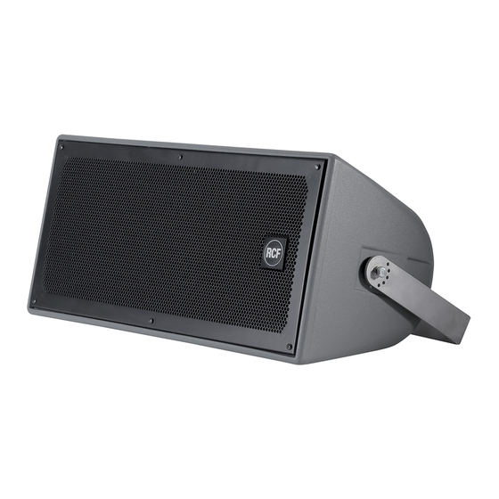
- Page 6 Il collegamento all’amplificatore è effettuato tramite un connettore a tenuta stagna. Il modello P 4228 include un driver per le alte frequenze al neodimio “RCF Precision” da 1,5” (membrana da 2,5”) caricato a tromba con direttività costante e 2 woofer da 8” (bobina da 2,5”) per le basse frequenze.
- Page 7 figura 4 figura 5 Ricollegare i conduttori e rimontare il driver a tromba (figura 4). Rimettere la griglia di protezione (figura 5). INSTALLAZIONE DI UN SINGOLO DIFFUSORE L’installazione dei diffusori deve essere effettuata da personale qualificato rispettando gli standard di sicurezza.
- Page 8 INSTALLAZIONE A CLUSTER Riferirsi al manuale degli accessori per l’installazione a “cluster” dei diffusori. COLLEGAMENTO ATTENZIONE: per il collegamento del diffusore si raccomanda di rivolgersi a personale qualificato ed addestrato, ossia personale avente conoscenze tecniche o esperienza o istruzioni specifiche sufficienti per permettergli di realizzare correttamente le connessioni e prevenire i pericoli dell’elettricità.
- Page 9 USCITA PARALLELA INGRESSO MAX. Ø : 2.5 mm MAX. Ø : 2.5 mm Osservando la parte posteriore del connettore , collegare il conduttore proveniente dall’uscita + dell’amplificatore al contatto 1 e l’altro conduttore (uscita – dell’amplificatore) al contatto 2, poi fissare il connettore al guscio posteriore I contatti 3 e 4 sono un’uscita parallela (per il collegamento di un altro diffusore) riportante il segnale...
-
Page 10: Dati Tecnici
DATI TECNICI SISTEMA P 4228 Impedenza 8 Ω Max. potenza d’ingresso (RMS) 400 W Max. potenza d’ingresso (picco) 1600 W Potenza raccomandata dell’amplificatore 800 W Sensibilità (1 W, 1 m) 97 dB Max. pressione sonora (1 m) 129 dB (P: 1600 W) Risposta in frequenza (–... -
Page 11: Safety Precautions
RCF S.p.A. will not assume any responsibility for the incorrect installation and / or use of this product. - Page 12 10. There are numerous mechanical and electrical factors to be considered when installing a professional audio system (in addition to those which are strictly acoustic, such as sound pressure, angles of coverage, frequency response, etc.). 11. Hearing loss Exposure to high sound levels can cause permanent hearing loss. The acoustic pressure level that leads to hearing loss is different from person to person and depends on the duration of exposure.
-
Page 13: Description
Each cabinet is equipped with four M 8 brass inserts and a stainless steel U-Bracket. Connections to an amplifier are made through a watertight connector. The high frequency section has a constant directivity horn with a 1.5 RCF Precision Neodymium compression driver (2.5” diaphragm). -
Page 14: Single Loudspeaker Installation
picture 4 picture 5 Reconnect the wires and remount the horn loaded driver (picture 4). Remount the protection grille (picture 5). SINGLE LOUDSPEAKER INSTALLATION Loudspeakers are to be install by qualified personnel, respecting all safety standards. Loudspeakers are to be installed securely. Make sure the support structure (walls / ceilings) has the necessary mechanical characteristics for the loudspeaker weight, without the risk of a fall that could damage things or cause an injury. -
Page 15: Array / Cluster Installation
ARRAY / CLUSTER INSTALLATION Please refer to the optional accessory user’s manual. CONNECTION WARNING: loudspeaker connections should be only made by qualified and experienced personnel having the technical know-how or sufficient specific instructions (to ensure that connections are made correctly) in order to prevent any electrical danger. To prevent any risk of electric shock, do not connect loudspeakers when the amplifier is switched on. -
Page 16: Notes About Low Impedance Connections
PARALLEL OUT INPUT MAX. Ø : 2.5 mm MAX. Ø : 2.5 mm Locking at the rear side of the female contact insert , connect the wire coming from the amplifier output + to the contact 1 and the other wire (amplifier output - ) to the contact 2, then fix the contact insert to the back shell The contacts 3 and 4 can be used as a parallel output (to link another loudspeaker) having the... -
Page 17: Specifications
SPECIFICATIONS SYSTEM P 4228 Impedance 8 Ω Max. input power (RMS) 400 W Max. input power (peak) 1600 W Recommended amplifier power 800 W Sensitivity (1 W, 1 m) 97 dB Max. sound pressure level (1 m) 129 dB (P: 1600 W) Frequency response (–... - Page 18 Except possible errors and omissions. RCF S.p.A. reserves the right to make modifications without prior notice. the rules of sound RCF SpA: Via Raffaello, 13 - 42124 Reggio Emilia Italy > tel. +39 0522 274411 - fax +39 0522 274484 - e-mail: rcfservice@rcf.it...
Need help?
Do you have a question about the P4228 and is the answer not in the manual?
Questions and answers