
Related Manuals for RCF PL 70EN


Summary of Contents for RCF PL 70EN
- Page 1 USER MANUAL MANUALE D’USO PL 70EN FLUSH-MOUNT CEILING LOUDSPEAKER IN COMPLIANCE WITH EN 54-24 STANDARD DIFFUSORE ACUSTICO PER CONTROSOFFITTO CONFORME ALLA NORMA EN 54-24...
- Page 3 INDEX INDICE ENGLISH SAFETY AND OPERATING PRECAUTIONS DESCRIPTION INSTALLATION CONNECTION NOTES ABOUT CONSTANT VOLTAGE SYSTEMS SPECIFICATIONS ITALIANO AVVERTENZE PER LA SICUREZZA E PRECAUZIONI D’USO DESCRIZIONE INSTALLAZIONE COLLEGAMENTO NOTE SUI SISTEMI A TENSIONE COSTANTE DATI TECNICI...
-
Page 4: Safety And Operating Precautions
RCF S.p.A. will not assume any responsibility for the incorrect installation and / or use of this product. SAFETY AND OPERATING PRECAUTIONS 1. - Page 5 9. RCF S.p.A. strongly recommends this product is only installed by professional qualified installers (or specialised firms) who can ensure a correct installation and certify it according to the regulations in force. The entire audio system must comply with the current standards and regulations regarding electrical systems.
-
Page 6: Installation
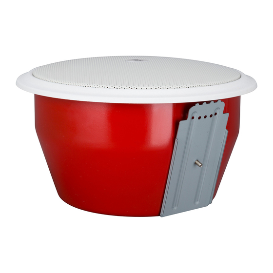
HAS BEEN DESIGNED TO GUARANTEE RELIABILITY AND HIGH PERFORMANCE. DESCRIPTION The PL 70EN ceiling loudspeaker is in compliance with EN 54-24 standard. It is equipped with a fire protection steel base and can be installed flush-mounted in false ceilings or panels. - Page 7 1. Drill a hole of diameter 205 mm ø205 mm (8.07") (8.07”) in the false ceiling panel, as shown in figure 1. FIGURE 1 2. Loosen the two wing bolts A (figure 2) that secure the two attachment plates B and move the plates upwards, then secure the two plates B by retightening the two wing bolts A.
- Page 8 5. Hang the speaker into the base, fitting the ends of one of the two support springs C on the speaker into one of the hooks D on the base (as shown in figure 4). 6. Make the electrical connections as described in the next manual section.
-
Page 9: Terminal Strip Connection
TERMINAL STRIP CONNECTION 70V/100V FIGURE 5 Connections with the audio line are made by using the two ceramic terminal strips situated inside the base and can be made even without the presence of the speaker, which can be installed at a later time. The IN +/– terminals are used for audio signal input and the OUT +/–... - Page 10 LINE TRANSFORMER CONNECTION The line transformer F (figure 2) of the loudspeaker is connected to the terminal strip on the base through the two conductors with FASTON connectors. Power selection (see figure 6): 1. Connect the FASTON connector marked COM (black wire) to the terminal 5 (COM) on the line transformer of the speaker.
-
Page 11: Notes About Constant Voltage Systems
NOTES ABOUT CONSTANT VOLTAGE SYSTEMS - The loudspeaker input voltage (Vd) shall correspond to the amplifier output voltage (Va). - The sum of nominal power values (Pd x n) of all loudspeakers connected to the line shall not exceed the amplifier power (Pa). - Make sure all loudspeakers are connected in phase to ensure a correct sound reproduction. -
Page 12: Specifications
SPECIFICATIONS INPUT VOLTAGE: 100 V – (70 V) POWER (SELECTABLE): 6 W – 3 W – 1.5 W – 0.75 W (power values are halved at 70 V) INPUT IMPEDANCE: 1.67 kΩ (6 W) – 3.33 kΩ (3 W) - 6.67 kΩ (1.5 W) – 13.33 kΩ (0.75 W) FREQUENCY RESPONSE: 145 Hz ÷... - Page 13 INDICE AVVERTENZE PER LA SICUREZZA E PRECAUZIONI D’USO DESCRIZIONE INSTALLAZIONE COLLEGAMENTO NOTE SUI SISTEMI A TENSIONE COSTANTE DATI TECNICI...
-
Page 14: Avvertenze Per La Sicurezzae Precauzioni D'uso
L’installazione e l’utilizzo errati del prodotto esimono la RCF S.p.A. da ogni responsabilità. AVVERTENZE PER LA SICUREZZA E PRECAUZIONI D’USO 1. - Page 15 9. La RCF S.p.A. raccomanda vivamente che l’installazione di questo prodotto sia eseguita solamente da installatori professionali qualificati (oppure da ditte specializzate) in grado di farla correttamente e certificarla in accordo con le normative vigenti.
-
Page 16: Installazione
REALIZZATO IN MODO DA GARANTIRNE L’AFFIDABILITÀ E PRESTAZIONI ELEVATE. DESCRIZIONE PL 70EN è un diffusore acustico a plafoniera conforme alla norma EN 54- 24 e provvisto di fondello antifiamma in acciaio, installabile ad incasso in controsoffittature o pannelli. È particolarmente indicato per la diffusione di messaggi di allarme: la sua caratteristica principale è... - Page 17 1. Praticare nella controsoffittatura un foro del diametro di 205 mm, ø205 mm come indicato in figura 1. FIGURA 1 2. Svitare i due bulloni ad alette A (figura 2) che bloccano le due piastre di fissaggio B e spostare queste ultime verso l’alto;...
- Page 18 5. Appendere il diffusore al fondello, incastrando le estremità di una delle due molle di sostegno C del diffusore in uno dei ganci D del fondello (come mostrato in figura 4). 6. Eseguire i collegamenti elettrici come descritto nella successiva sezione del manuale.
- Page 19 COLLEGAMENTO DELLA MORSETTIERA 70V/100V FIGURA 5 I collegamenti con la linea audio si realizzano tramite i due morsetti ceramici presenti all’interno del fondello e possono essere effettuati anche senza la presenza del diffusore, che può essere installato in un secondo momento. I morsetti IN +/–...
- Page 20 COLLEGAMENTO DEL TRASFORMATORE DI LINEA Il trasformatore di linea F (figura 2) del diffusore è collegato alla morsettiera del fondello tramite i 2 conduttori intestati con connettori FASTON. Impostazione della potenza (vedere la figura 6): 1. collegare il connettore FASTON contrassegnato con COM (filo nero) al contatto 5 (COM) del trasformatore di linea;...
-
Page 21: Note Sui Sistemi A Tensione Costante
NOTE SUI SISTEMI A TENSIONE COSTANTE - La tensione d’ingresso del diffusore (Vd) deve corrispondere con la tensione d’uscita dell’amplificatore (Va). - La somma delle potenze nominali di tutti i diffusori (Pd x n) collegati alla linea non deve superare quella dell’amplificatore (Pa). - Per garantire una corretta riproduzione audio, effettuare il collegamento di tutti i diffusori “in fase”. -
Page 22: Dati Tecnici
DATI TECNICI TENSIONE D’INGRESSO: 100 V – (70 V) POTENZA (SELEZIONABILE): 6 W – 3 W – 1,5 W – 0,75 W (i valori sono dimezzati a 70 V) IMPEDENZA D’INGRESSO: 1,67 kΩ (6 W) – 3,33 kΩ (3 W) 6,67 kΩ... - Page 23 1488 RCF S.p.A. - Via Raffaello Sanzio 13, 42124 Reggio Emilia, ITALY 1488-CPR-0487/W EN 54-24:2008 Loudspeaker for voice alarm systems for fire detection and fire alarm systems for buildings PL 70EN Type A DoP: 002_14 Other technical data: see operational manual.
- Page 24 Except possible errors and omissions. RCF S.p.A. reserves the right to make modifications without prior notice. Salvo eventuali errori ed omissioni. RCF S.p.A. si riserva il diritto di apportare modifiche senza preavviso. www.rcf.it HEADQUARTERS: RCF S.p.A. Italy tel. +39 0522 274 411 e-mail: info@rcf.it...
Need help?
Do you have a question about the PL 70EN and is the answer not in the manual?
Questions and answers