Table of Contents
Advertisement
Chapter 1. Getting Started
Getting Started
Thank you for purchasing the MS-6555 v1.X Micro ATX mainboard. The
MS-6555 is based on Intel
efficiency. Designed to fit the advanced Intel
478 pin package, the MS-6555 delivers a high performance and professional
desktop platform solution.
TOPICS
Mainboard Specification
Mainboard Layout
Quick Components Guide
MSI Special Features
Brookdale-G & ICH4 chipsets for optimal system
®
Pentium
®
1-1
Getting Started
1
4 processors in the
®
1-2
1-4
1-5
1-6
Advertisement
Table of Contents

Related Manuals for MSI MS-6555


Summary of Contents for MSI MS-6555
-
Page 1: Chapter 1. Getting Started
Getting Started Chapter 1. Getting Started Getting Started Thank you for purchasing the MS-6555 v1.X Micro ATX mainboard. The MS-6555 is based on Intel Brookdale-G & ICH4 chipsets for optimal system ® efficiency. Designed to fit the advanced Intel Pentium 4 processors in the ®... -
Page 2: Mainboard Specification
Chapter 1 Mainboard Specification Supports Intel Pentium 4 processor in 478-pin package. ® ® Supports 1.5GHz, 1.6GHz, 1.7GHz, 1.8GHz, 1.9GH z, 2GHz and up. Chipset Intel Brookdale-G/GL chipset ® - Integrated video accelerator. - AGP 4x universal slot (G). - Support 100/133 MHz FSB. - Support 400/533 MHz Intel NetBurst micro-architecture bus. - Page 3 Getting Started - 6 USB 2.0 ports (Rear * 2 / Front * 4) - PS2 K/B connector - 1 Line-In/Line-Out/Mic-In/Game port - 1 RJ45 connector (optional) Audio AC97 2.2 interface provided by ICH4 2 channel S/W audio codec - AC'97 2.2 Compliant - Meet PC2001 audio performance requirement LAN (optional) RealTek RTL8100BL.
-
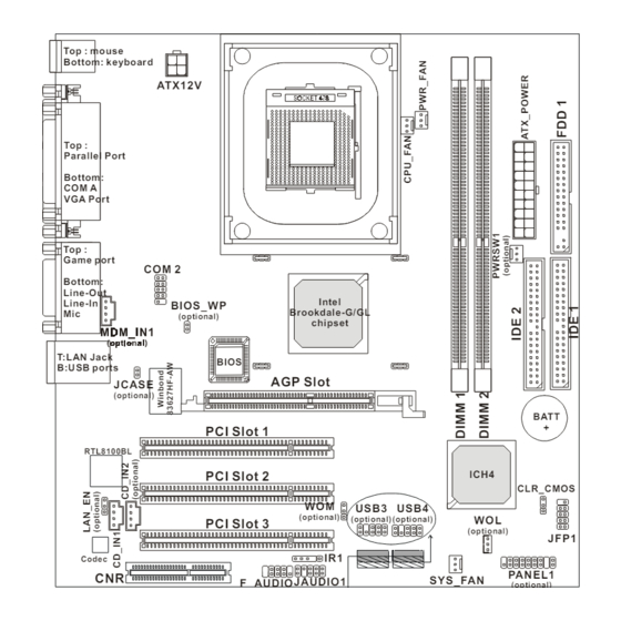
Page 4: Mainboard Layout
B:USB ports AGP Slot JCASE (optional) BATT PCI Slot 1 RTL8100BL PCI Slot 2 ICH4 CLR_CMOS USB3 USB4 (optional) (optional) (optional) PCI Slot 3 (optional) JFP1 Codec PANEL1 SYS_FAN JAUDIO1 F_AUDIO (optional) (optional) USB1 USB2 MS-6555 v1.X Micro ATX Mainboard... -
Page 5: Quick Components Guide
Getting Started Quick Components Guide Component Function Reference Socket 478 Installing CPU See p. 2-2 DDR1~2 Installing DDR modules See p. 2-5 ATX Power Connector Installing power supply See p. 2-7 USB Connectors Connecting to USB devices See p. 2-9 COM A &... -
Page 6: Msi Special Features
Chapter 1 MSI Special Features PC Alert™ III The PC Alert III is a utility you can find in the CD-ROM disk. The utility is just like your PC doctor that can de- tect the following PC hardware status during real time operation: * monitor CPU &... -
Page 7: Hardware Setup
Hardware Setup Chapter 2. Hardware Setup Hardware Setup This chapter provides you with the information about hardware setup procedures. While doing the installation, be careful in holding the components and follow the installation procedures. For some components, if you install in the wrong orientation, the components will not work properly. -
Page 8: Central Processing Unit (Cpu)
Chapter 2 Central Processing Unit: CPU ® ® The mainboard supports Intel Pentium 4 processor in the 478 pin package. The mainboard uses a CPU socket called PGA478 for easy CPU installation. When you are installing the CPU, make sure the CPU has a heat sink and a cooling fan attached on the top to prevent overheating. -
Page 9: Installing The Cpu Fan
Hardware Setup Installing the CPU Fan As processor technology pushes to faster speeds and higher performance, thermal management becomes increasingly important. To dissi- pate heat, you need to attach the CPU cooling fan and heatsink on top of the CPU. Follow the instructions below to install the Heatsink/Fan: Locate the CPU and its retention Position the heatsink onto the reten- mechanism on the motherboard. -
Page 10: Cpu Core Speed Derivation Procedure
Chapter 2 Connect the fan power cable from the mounted fan to the 3-pin fan power connector on the board. fan power cable CPU Core Speed Derivation Procedure CPU Clock 100MHz Core/Bus ratio then CPU core speed Host Clock x Core/Bus ratio 100MHz x 14 1.4GHz Overclocking... -
Page 11: Introduction To Ddr Sdram
Hardware Setup Memory The mainboard provides 2 slots for 184-pin, 2.5V DDR DIMM with 4 memory banks. You can install DDR200/PC1600 or DDR266/PC2100 DDR SDRAM modules on the DDR DIMM slots (DDR 1~2). To operate properly, at least one DIMM module must be installed. Introduction to DDR SDRAM DDR (Double Data Rate) SDRAM is similar to conventional SDRAM, but doubles the rate by transferring data twice per cycle. -
Page 12: Ddr Module Combination
Chapter 2 DDR Module Combination You can install either single sided or double sided 184-pin DDR DIMM modules into DDR DIMM slots to meet your needs. Different from the SDR DIMM, the DDR DIMM has only one notch on the center of module. The number of pins on either side of the breaks are different. -
Page 13: Power Supply
Hardware Setup Power Supply The mainboard supports ATX power supply for the power system. Be- fore inserting the power supply connector, always make sure that all compo- nents are installed properly to ensure that no damage will be caused. ATX 20-Pin Power Connector: ATX_POWER This connector allows you to connect to an ATX power supply. -
Page 14: Back Panel
Chapter 2 Back Panel The Back Panel provides the following connectors: Midi/Joystick Parallel (optional) Mouse L-out L-in MIC Keyboard COM A Mouse Connector ® The mainboard provides a standard PS/2 mouse mini DIN connector for ® ® attaching a PS/2 mouse. -
Page 15: Keyboard Connector
Hardware Setup Keyboard Connector ® The mainboard provides a standard PS/2 keyboard mini DIN connector ® ® for attaching a PS/2 keyboard. You can plug a PS/2 keyboard directly into this connector. Pin Definition SIGNAL DESCRIPTION Keyboard DATA Keyboard DATA No connection Ground Keyboard Clock... -
Page 16: Vga Db 15 Pin Connector
Chapter 2 Serial Port Connector: COM A & COM 2 One 9-pin male DIN serial port COM A and one 9-pin COM2 pin header are supplied. You can attach a serial mouse or other serial devices to the connectors. 1 2 3 4 5 Pin Definition SIGNAL DESCRIPTION... -
Page 17: Joystick/Midi Connectors
Hardware Setup Joystick/Midi Connectors You can connect a joystick or game pad to this connector. Audio Port Connectors Line Out is a connector for Speakers or Headphones. Line In is used for external CD player, Tape player, or other audio devices. Mic is a connector for microphones. -
Page 18: Parallel Port Connector: Lpt1
Chapter 2 Parallel Port Connector: LPT1 The mainboard provides a 25-pin female centronic connector as LPT. A parallel port is a standard printer port that supports Enhanced Parallel Port (EPP) and Extended Capabilities Parallel Port (ECP) mode. Pin Definition SIGNAL DESCRIPTION STROBE Strobe... -
Page 19: Floppy Disk Drive Connector: Fdd1
Hardware Setup Connectors The mainboard provides connectors to connect to FDD, IDE HDD, case, modem, LAN, USB Ports, IR module and CPU/System FAN. Floppy Disk Drive Connector: FDD1 The mainboard provides a standard floppy disk drive connector that supports 360K, 720K, 1.2M, 1.44M and 2.88M floppy disk types. FDD1 Independent Power Switch Connector: PWRSW1 (Optional) The connector is connected to an independent power switch on the... -
Page 20: Hard Disk Connectors: Ide1 & Ide2
Chapter 2 Hard Disk Connectors: IDE1 & IDE2 The mainboard has a 32-bit Enhanced PCI IDE and Ultra DMA 33/66/100 controller that provides PIO mode 0~4, Bus Master, and Ultra DMA33/66/100 function. You can connect up to four hard disk drives, CD-ROM, 120MB Floppy (reserved for future BIOS) and other devices. - Page 21 Hardware Setup CD-In Connector: CD_IN1/CD_IN2 (Optional) The connector is for CD-ROM audio connector. Modem-In Connector: MDM_IN1 (Optional) The connector is for modem with internal audio connector. Mono_Out MDM_IN1 Phone_In CD_IN1/ CD_IN2 2-15...
- Page 22 Chapter 2 Fan Power Connectors: CPU_FAN/PWR_FAN/SYS_FAN The CPU_FAN (processor fan), PWR_FAN (power supply fan) & SYS_FAN (system fan) support system cooling fan with +12V. It supports three-pin head connector. When connecting the wire to the connectors, al- ways take note that the red wire is the positive and should be connected to the +12V, the black wire is Ground and should be connected to GND.
-
Page 23: Irda Infrared Module Header: Ir1
Hardware Setup Chassis Intrusion Switch Connector: JCASE (Optional) This connector is connected to 2-pin connector chassis switch. If the Chassis is open, the switch will be short. The system will record this status. To clear the warning, you must enter the BIOS settting and clear the status. JCASE IrDA Infrared Module Header: IR1 The connector allows you to connect to IrDA Infrared module. - Page 24 Chapter 2 Wake On Ring Connector: WOM (Optional) This connector allows you to connect to a modem card with Wake On Ring function. The connector will power up the system when a signal is re- ceived through the modem card. MDM_WAKEUP 5VSB Wake On LAN Connector: WOL (Optional)
- Page 25 Hardware Setup Front Panel Connector: JFP1 or PANEL1 (optional) The mainboard provides one front panel connector for electrical connec- tion to the front panel switches and LEDs. Users can choose either the JFP1 or the PANEL1 depending on their needs. The difference between JFP1 & PANEL1 ®...
- Page 26 Chapter 2 Front Panel Audio Connector: JAUDIO1 or F_AUDIO(optional) The mainboard provides one front panel audio connector for connection to the front panel audio. Users can choose either the JAUDIO1 or the F_AUDIO depending on their needs. The difference between JAUDIO1 & F_AUDIO is ®...
- Page 27 Hardware Setup Note: To have the Line-out connector on the back panel work properly, you need to place jumpers on pin# 5~8 (F_AUDIO) or on pin#5~6 and 9~10 (JAUDIO1) of the front panel audio connector. Otherwise, this Line-out connector will not function and nothing can be heard through speakers or headphones attached to the Line-out connector on the back panel.
- Page 28 Chapter 2 Front USB Connector: USB1/2 or USB3/4 The mainboard provides two USB 2.0 pinheaders (optional USB 2.0 Bracket available). Users can choose either the USB1/USB2 or the USB3/USB4 depending on their needs. The difference between USB1/USB2 & USB3/USB4 ® is that USB1/USB2 are compliant with Intel Front Panel I/O Connectivity Design Guide.
- Page 29 Hardware Setup Jumpers The motherboard provides one jumper for you to set the computer’s function. This section will explain how to change your motherboard’s function through the use of the jumper. Clear CMOS Jumper: CLR_CMOS There is a CMOS RAM on board that has a power supply from external battery to keep the data of system configuration.
-
Page 30: Lan Enable/Disable Jumper: Lan_En (Optional)
Chapter 2 LAN Enable/Disable Jumper: LAN_EN (Optional) This jumper is used to enable or disable the onboard LAN function and is available only when LAN is integrated on the mainboard. LAN_EN Onboard LAN Enable Onboard LAN Disable BIOS Flash Jumper: BIOS_WP (Optional) This jumper is used to lock or unlock the boot block area on BIOS. -
Page 31: Agp (Accelerated Graphics Port) Slot
Hardware Setup Slots The motherboard provides three 32-bit Master PCI bus slots, one AGP slot and one CNR slot. AGP Slot PCI Slots CNR Slot AGP (Accelerated Graphics Port) Slot The AGP slot allows you to insert the AGP graphics card. AGP is an interface specification designed for the throughput demands of 3D graphics. -
Page 32: Pci Interrupt Request Routing
Chapter 2 PCI Interrupt Request Routing The IRQ, abbreviation of interrupt request line and pronounced I-R-Q, are hardware lines over which devices can send interrupt signals to the microprocessor. The PCI IRQ pins are typically connected to the PCI bus INT A# ~ INT D# pins as follows: Order 1 Order 2... -
Page 33: Award Bios Setup
AWARD BIOS Setup ® ® Chapter 3. AWARD BIOS Setup ® AWARD BIOS Setup This chapter provides information on the AWARD ® BIOS Setup program and allows you to configure the system for optimum use. You may need to run the Setup program when: An error message appears on the screen during the system booting up, and requests you to run SETUP. -
Page 34: Entering Setup
Chapter 3 Entering Setup Power on the computer and the system will start POST (Power On Self Test) process. When the message below appears on the screen, press <DEL> key to enter Setup. Press DEL to enter SETUP If the message disappears before you respond and you still wish to enter Setup, restart the system by turning it OFF and On or pressing the RESET button. -
Page 35: Getting Help
AWARD BIOS Setup ® Getting Help After entering the Setup menu, the first menu you will see is the Main Menu. Main Menu The main menu lists the setup functions you can make changes to. You can use the control keys ( ↑↓ ) to select the item. The on-line description of the high- lighted setup function is displayed at the bottom of the screen. -
Page 36: The Main Menu
Chapter 3 The Main Menu ® Once you enter Award BIOS CMOS Setup Utility, the Main Menu (Figure 1) will appear on the screen. The Main Menu allows you to select from twelve setup functions and two exit choices. Use arrow keys to select among the items and press <Enter>... - Page 37 AWARD BIOS Setup ® PnP/PCI Configurations This entry appears if your system supports PnP/PCI. PC Health Status This entry shows your PC health status. Frequency/Voltage Control Use this menu to specify your settings for frequency/voltage control. Load Fail-Safe Defaults Use this menu to load the BIOS default values for minimal but stable system performance.
-
Page 38: Standard Cmos Features
Chapter 3 Standard CMOS Features The items in Standard CMOS Features Menu are divided into 10 categories. Each category includes no, one or more than one setup items. Use the arrow keys to highlight the item and then use the <PgUp> or <PgDn> keys to select the value you want in each item. - Page 39 AWARD BIOS Setup ® ing items. Enter the information directly from the keyboard. This information should be provided in the documentation from your hard disk vendor or the system manufacturer. If the controller of HDD interface is SCSI, the selection shall be “None”. If the controller of HDD interface is CD-ROM, the selection shall be “None”.
-
Page 40: Advanced Bios Features
Chapter 3 Advanced BIOS Features Anti-Virus Protection The item is to set the Virus Warning feature for IDE Hard Disk boot sector protection. If the function is enabled and any attempt to write data into this area is made, BIOS will display a warning message on screen and beep. Settings: Disabled and Enabled. - Page 41 AWARD BIOS Setup ® 1st/2nd/3rd Boot Device The items allow you to set the sequence of boot devices where BIOS attempts to load the disk operating system. The settings are: Floppy The system will boot from floppy drive. LS120 The system will boot from LS-120 drive. HDD-0 The system will boot from the first HDD.
- Page 42 Chapter 3 Typematic Rate Setting This item is used to enable or disable the typematic rate setting including Typematic Rate & Typematic Delay. Typematic Rate (Chars/Sec) After Typematic Rate Setting is enabled, this item allows you to set the rate (characters/second) at which the keys are accelerated.
- Page 43 AWARD BIOS Setup ® Full Screen LOGO Show This item enables you to show the company logo on the bootup screen. Set- tings are: Disabled Shows the POST messages at boot. Enabled Shows a still image (logo) on the full screen at boot. 3-11...
-
Page 44: Advanced Chipset Features
Chapter 3 Advanced Chipset Features The Advanced Chipset Features Setup option is used to change the values of the chipset registers. These registers control most of the system options in the computer. Note: Change these settings only if you are familiar with the chipset. Configure DRAM Timing This setting determines whether DRAM timing is configured by reading the contents of the SPD (Serial Presence Detect) EPROM on the DRAM module. - Page 45 AWARD BIOS Setup ® RAS# to CAS# Delay When DRAM is refreshed, both rows and columns are addressed separately. This setup item allows you to determine the timing of the transition from RAS (row address strobe) to CAS (column address strobe). The less the clock cycles, the faster the DRAM performance.
- Page 46 Chapter 3 On-Chip Frame Buffer Size The field specifies the size of system memory allocated for video memory. Setting options: 1MB, 8MB. Delay Prior to Thermal When the CPU temperature reaches a factory preset level, a thermal monitoring mechanism will be enabled following the appropriate timing delay specified in this field.
-
Page 47: Integrated Peripherals
AWARD BIOS Setup ® Integrated Peripherals On-Chip Primary/Secondary PCI IDE The integrated peripheral controller contains an IDE interface with support for two IDE channels. Choose Enabled to activate each channel separately. IDE Primary/Secondary Master/Slave PIO The four items allow you to set a PIO (Programmed Input/Output) mode for each of the four IDE devices that the onboard IDE interface supports. - Page 48 Chapter 3 USB Controller Select Enabled if your system contains a Universal Serial Bus (USB) controller and you have USB peripherals. The settings are: Enabled, Disabled. USB Keyboard/Mouse Support Set to Enabled if your need to use an USB keyboard/mouse in the operating system that does not support or have any USB driver installed, such as DOS and SCO Unix.
- Page 49 AWARD BIOS Setup ® Serial Port A/B The items specify the base I/O port address and IRQ for the onboard Serial Port A/Serial Port B. Selecting Auto allows BIOS to automatically determine the correct base I/O port address. Settings: Disabled, 3F8/IRQ4, 2F8/IRQ3, 3E8/ IRQ4, 2E8/IRQ3 and Auto.
- Page 50 Chapter 3 SPP/EPP/ECP/ECP+EPP To operate the onboard parallel port as Standard Parallel Port only, choose “SPP.” To operate the onboard parallel port in the EPP mode simultaneously, choose “EPP.” By choosing “ECP”, the onboard parallel port will operate in ECP mode only. Choosing “ECP + EPP” will allow the onboard parallel port to support both the ECP and EPP modes simultaneously.
-
Page 51: Power Management Setup
AWARD BIOS Setup ® Power Management Setup The Power Management Setup allows you to configure you system to most effectively save energy while operating in a manner consistent with your own style of computer use. ACPI Function This item is to activate the ACPI (Advanced Configuration and Power Man- agement Interface) Function. - Page 52 Chapter 3 memory will be used to restore the PC to the previous state when an “wake up” event occurs. Power Management/APM This item is used to select the degree (or type) of power saving and is related to these modes: Suspend Mode and HDD Power Down. There are three op- tions for power management: Min Saving Minimum Power Management.
- Page 53 AWARD BIOS Setup ® CPU THRM-Throttling The item allows you to specify the CPU speed (at percentage) to which it will slow down when the CPU reaches the predetermined overheat temperature. Settings range from 12.5% to 87.5% at 12.5% increment. Resume by RTC Alarm The field is used to enable or disable the feature of booting up the system on a scheduled time/date.
- Page 54 Chapter 3 Reload Global Timer Events: Primary/Secondary Master/Slave IDE, FDC/ LPT/COM Ports Global Timer Events are I/O events whose occurrence can prevent the system from entering a power saving mode or can awaken the system from such a mode. In effect, the system remains alert for anything which occurs to a device that is configured as Enabled, even when the system is in a power down mode.
-
Page 55: Pnp/Pci Configurations
AWARD BIOS Setup ® PNP/PCI Configurations This section describes configuring the PCI bus system. PCI, or Peripheral Component Interconnect, is a system which allows I/O devices to operate at speeds nearing the speed the CPU itself uses when communicating with its own special components. - Page 56 Chapter 3 Press <Enter> and you will enter the sub-menu of the items. IRQ Resources list IRQ 3/4/5/7/9/10/11/12/14/15 for users to set each IRQ a type depending on the type of device using the IRQ. Settings are: PCI Device For Plug & Play compatible devices designed for PCI bus architecture.
-
Page 57: Pc Health Status
AWARD BIOS Setup ® PC Health Status This section monitors the current hardware status including CPU/system temperature, CPU/system fan speeds, Vcore etc. Monitor function is available only if there is hardware monitoring mechanism onboard. Current System/CPU Temperature, CPU/System/Power Fan, Vcore, VTT, 3. 3V, +5V, +12V, -12V, -5V, VBAT(V), 5VSB(V) These items display the current status of all of the monitored hardware de- vices/components such as CPU voltages, temperatures and all fans’... -
Page 58: Frequency/Voltage Control
Chapter 3 Frequency/Voltage Control This section controls the frequency/voltage of the CPU and certain onboard hardware to enhance overall system performance. CPU Ratio Selection This setting controls the multiplier that is used to determine the internal clock speed of the processor relative to the external or motherboard clock speed. Auto Detect PCI Clock This item is used to auto detect the PCI slots. - Page 59 AWARD BIOS Setup ® CPU Host/3V66/PCI Clock This setting specifies the clock frequencies of the CPU host bus (FSB), AGP (VGA) bus, and PCI buses. It provides a method for end users to overclock the processor accordingly. When set to Default, the BIOS will use the default clock frequencies for the CPU host bus, AGP bus, and PCI buses.
-
Page 60: Load Fail-Safe/Optimized Defaults
Chapter 3 Load Fail-Safe/Optimized Defaults The two options on the main menu allow users to restore all of the BIOS settings to the default Fail-Safe or Optimized values. The Optimized Defaults are the default values set by the mainboard manufacturer specifically for opti- mal performance of the mainboard. -
Page 61: Set Supervisor/User Password
AWARD BIOS Setup ® Set Supervisor/User Password When you select this function, a message as below will appear on the screen: Type the password, up to six characters in length, and press <Enter>. The password typed now will replace any previously set password from CMOS memory.
Need help?
Do you have a question about the MS-6555 and is the answer not in the manual?
Questions and answers