Draytek Vigor 2110 Series User Manual
Hide thumbs
Also See for Vigor 2110 Series:
- Specifications (2 pages) ,
- Declaration of conformity (1 page) ,
- User manual (310 pages)
Table of Contents
Advertisement
Quick Links
Download this manual
See also:
User Manual
Advertisement
Table of Contents

Related Manuals for Draytek Vigor 2110 Series


Summary of Contents for Draytek Vigor 2110 Series
-
Page 2: User Guide
Vigor2110 Series Broadband Firewall Router User Guide Version: 1.0(UK) Date: 15/04/2009 Vigor2110 Series User’s Guide... - Page 3 Owner http://www.draytek.com. Firmware & Tools Due to the continuous evolution of DrayTek technology, all routers may be regularly Updates updated with new firmware. Please consult the DrayTek UK web site for more information on newest firmware, tools and documents. Please also check the UK web site for the full product specification and accessories as this can vary depending on your locality/market.
-
Page 4: Regulatory Information
Product: Vigor2110 Series Router DrayTek Corp. declares that Vigor2110 Series of routers are in compliance with the following essential requirements and other relevant provisions of R&TTE Directive 1999/5/EEC. The product conforms to the requirements of Electro-Magnetic Compatibility (EMC) Directive 2004/108/EC by complying with the requirements set forth in EN55022/Class B and EN55024/Class B. -
Page 5: Table Of Contents
Preface .......................1 1.1 Web Configuration Buttons Explanation ................. 1 1.2 LED Indicators and Connectors ....................2 1.2.1 For Vigor2110 ........................2 1.2.2 For Vigor2110n ......................... 4 1.2.3 For Vigor2110Vn....................... 6 1.3 Hardware Installation ......................8 1.4 Printer Installation ........................8 Configuring Basic Settings ................15 2.1 Two-Level Management...................... - Page 6 3.5.4 Status..........................58 3.6 Wireless LAN ........................59 3.6.1 Basic Concepts....................... 59 3.6.2 General Setup......................... 61 3.6.3 Security ........................... 63 3.6.4 Access Control........................ 64 3.6.5 Station List ........................65 3.7 System Maintenance......................66 3.7.1 System Status......................... 66 3.7.2 User Password ....................... 68 3.7.3 Time and Date ........................
- Page 7 4.6.9 P2P Object........................117 4.6.10 Misc Object ......................... 118 4.7 CSM Profile ..........................119 4.7.1 IM/P2P Filter Profile...................... 120 4.7.2 URL Content Filter Profile..................... 121 4.7.3 Web Content Filter Profile..................... 125 4.8 Bandwidth Management ..................... 127 4.8.1 Sessions Limit....................... 127 4.8.2 Bandwidth Limit ......................128 4.9 Applications .........................
- Page 8 4.15.4 DHCP Table........................ 196 4.15.5 NAT Sessions Table ....................196 4.15.6 Data Flow Monitor....................... 197 4.15.7 Traffic Graph....................... 199 4.15.8 Ping Diagnosis......................199 4.15.9 Trace Route ........................ 200 Application and Examples ................201 5.1 Request a certificate from a CA server on Windows CA Server ......... 201 5.2 Request a CA Certificate and Set as Trusted on Windows CA Server .......
-
Page 9: Preface
The Vigor2110 series features advanced bandwidth control mechanism such as IP-layer QoS, NAT Session Limitation, Bandwidth Borrowed, etc., to allow easy, flexible, reliable access control and bandwidth management. The SPI (Stateful Packet Inspection) firewall uses object-based design to make settings of firewall policies easy. -
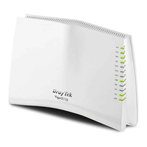
Page 10: Led Indicators And Connectors
Before you use the Vigor router, please get acquainted with the LED indicators and connectors first. Status Explanation Blinking The router is powered on and running (Activity) normally. The router is powered off. The profile(s) of CSM (Content Security Management) for IM/P2P, URL/Web Content Filter application can be enabled from Firewall >>General Setup. - Page 11 Interface Description Factory Reset Restore the default settings. Usage: Turn on the router (ACT LED is blinking). Press the hole and keep for more than 5 seconds. When you see the ACT LED begins to blink rapidly than usual, release the button. Then the router will restart with the factory default configuration.
-
Page 12: For Vigor2110
Status Explanation Blinking The router is powered on and running (Activity) normally. The router is powered off. WLAN Wireless access point is ready. Blinking It will blink while wireless traffic goes through. The WAN port is connected. Blinking It will blink while transmitting data. The port is connected. - Page 13 Interface Description Factory Reset Restore the default settings. Usage: Turn on the router (ACT LED is blinking). Press the hole and keep for more than 5 seconds. When you see the ACT LED begins to blink rapidly than usual, release the button. Then the router will restart with the factory default configuration.
-
Page 14: For Vigor2110Vn
Status Explanation Blinking The router is powered on and running (Activity) normally. The router is powered off. WLAN Wireless access point is ready. Blinking It will blink while wireless traffic goes through. The WAN port is connected. Blinking It will blink while transmitting data. The port is connected. - Page 15 Interface Description Line Connector of analog phone for PSTN life line. Phone2/Phone1 Connecter of analog phone for VoIP communication Factory Reset Restore the default settings. Usage: Turn on the router (ACT LED is blinking). Press the hole and keep for more than 5 seconds. When you see the ACT LED begins to blink rapidly than usual, release the button.
-
Page 16: Hardware Installation
You can install a printer onto the router for sharing printing. All the PCs connected this router can print documents via the router. The example provided here is made based on Windows XP/2000. For Windows 98/SE/Vista, please visit www.draytek.com. Vigor2110 Series User’s Guide... - Page 17 Before using it, please follow the steps below to configure settings for connected computers (or wireless clients). Connect the printer with the router through USB/parallel port. Open Start->Settings-> Printer and Faxes. Open File->Add a New Computer. A welcome dialog will appear. Please click Next. Vigor2110 Series User’s Guide...
- Page 18 Click Local printer attached to this computer and click Next. In this dialog, choose Create a new port Type of port and use the drop down list to select Standard TCP/IP Port. Click Next. Vigor2110 Series User’s Guide...
- Page 19 In the following dialog, type 192.168.1.1 (router’s LAN IP) in the field of Printer Name or IP Address and type IP_192.168.1.1 as the port name. Then, click Next. Click Standard and choose Generic Network Card. Then, in the following dialog, click Finish. Vigor2110 Series User’s Guide...
- Page 20 Now, your system will ask you to choose right name of the printer that you installed onto the router. Such step can make correct driver loaded onto your PC. When you finish the selection, click Next. 10. For the final stage, you need to go back to Control Panel-> Printers and edit the property of the new printer you have added.
- Page 21 Note 1: Some printers with the fax/scanning or other additional functions are not supported. If you do not know whether your printer is supported or not, please visit www.draytek.com to find out the printer list. Open Support >FAQ; find out the link of Printer Server and click it; then click the What types of printers are compatible with Vigor router? link.
- Page 22 This page is left blank. Vigor2110 Series User’s Guide...
-
Page 23: Configuring Basic Settings
For using the router properly, it is necessary for you to change the password of web configuration for security and adjust primary basic settings. This chapter explains how to setup a password for an administrator/user and how to adjust basic/advanced settings for accessing Internet successfully. For user mode operation, do not type any word on the window and click Login for the simple web pages for configuration. -
Page 24: Changing Password
No matter user mode operation or admin mode operation, please change the password for the original security of the router. Open a web browser on your PC and type http://192.168.1.1. A pop-up window will open to ask for username and password. Please type “admin/admin”... - Page 25 Main screen for user mode operation (simple configuration) Note: The home page will change slightly in accordance with the type of the router you have. Go to System Maintenance page and choose Administrator Password/User Password. Enter the login password (the default is blank) on the field of Old Password. Type New Password.
-
Page 26: Configuring Router For Internet Connectivity
Open Internet Access page and then check whether the ISP settings are set correctly. Click PPPoE/PPTP/Static or Dynamic IP link to review the settings that you configured previously. Note: The web page for Internet Access will change according to the mode (user/admin) operation you choose. - Page 27 Check if the Enable option is selected. Check if WAN IP Network Settings is set appropriately. Check if IP Address, Subnet Mask and Gateway are set correctly (must identify with the values from your ISP) if you choose Specify an IP address. Check if the Enable option for PPTP Link is selected.
-
Page 28: Online Status
Check if WAN IP Network Settings are set properly. If you select Specify an IP address, you have to type in the values of IP Address and Subnet Mask manually. Be sure the values that you type identify with the values from your ISP. The online status shows the system status, WAN status, ADSL Information and other status related to this router within one page. -
Page 29: Saving Configuration
Each time you click OK on the web page for saving the configuration, you can find messages showing the system interaction with you. Ready indicates the system is ready for you to input settings. Settings Saved means your settings are saved once you click Finish or OK button. Vigor2110 Series User’s Guide... - Page 30 Vigor2110 Series User’s Guide...
-
Page 31: User Mode Operation
This chapter will guide users to execute simple configuration through user mode operation. As for other examples of application, please refer to chapter 5. Open a web browser on your PC and type http://192.168.1.1. The window will ask for typing username and password. Do not type any word (both username and password are Null for user operation) on the window and click Login on the window. -
Page 32: Pppoe
As the router plays a role to manage and further protect its LAN, it interconnects groups of host PCs. Each of them has a private IP address assigned by the built-in DHCP server of the Vigor router. The router itself will also use the default private IP address: 192.168.1.1 to communicate with the local hosts. -
Page 33: Static Or Dynamic Ip
ISP Access Setup Enter your allocated username, password and authentication parameters according to the information provided by your ISP. Username – Type in the username provided by ISP in this field. Password – Type in the password provided by ISP in this field. WAN Connection Such function allows you to verify whether network connection Detection... - Page 34 Access Control Click Enable for activating this function. If you click Disable, this function will be closed and all the settings that you adjusted in this page will be invalid. Keep WAN Normally, this function is designed for Dynamic IP environments Connection because some ISPs will drop connections if there is no traffic within certain periods of time.
-
Page 35: Pptp
Domain Name: Type in the domain name that you have assigned. Specify an IP address Click this radio button to specify some data if you want to use Static IP mode. IP Address: Type the IP address. Subnet Mask: Type the subnet mask. Gateway IP Address: Type the gateway IP address. -
Page 36: Lan
IP Address Fixed IP - Usually ISP dynamically assigns IP address to you each Assignment time you connect to it and request. In some case, your ISP provides Method(IPCP) service to always assign you the same IP address whenever you request. -
Page 37: General Setup
This page provides you the general settings for LAN. Click LAN to open the LAN settings page and choose General Setup. IP Address Type in private IP address for connecting to a local private network (Default: 192.168.1.1). Subnet Mask Type in an address code that determines the size of the network. (Default: 255.255.255.0/ 24) DHCP Server DHCP stands for Dynamic Host Configuration Protocol. -
Page 38: Nat
address. Force DNS manual setting - Force Vigor router to use DNS servers in this page instead of DNS servers given by the Internet Access server (PPPoE, PPTP, L2TP or DHCP server). Primary IP Address -You must specify a DNS server IP address here because your ISP should provide you with usually more than one DNS Server. -
Page 39: Port Redirection
more IP addresses and/or service ports into different specified services. In other words, the NAT function can be achieved by using port mapping methods. Below shows the menu items for NAT. Port Redirection is usually set up for server related service inside the local network (LAN), such as web servers, FTP servers, E-mail servers etc. - Page 40 Press any number under Index to access into next page for configuring port redirection. Enable Check this box to enable such port redirection setting. Mode Two options (Single and Range) are provided here for you to choose. To set a range for the specific service, select Range. In Range mode, if the public port (start port and end port) and the starting IP of private IP had been entered, the system will calculate and display the ending IP of private IP automatically.
-
Page 41: Dmz Host
Private Port Specify the private port number of the service offered by the internal host. Note that the router has its own built-in services (servers) such as Telnet, HTTP and FTP etc. Since the common port numbers of these services (servers) are all the same, you may need to reset the router in order to avoid confliction. -
Page 42: Open Ports
Private IP Enter the private IP address of the DMZ host, or click Choose PC to select one. Choose PC Click this button and then a window will automatically pop up, as depicted below. The window consists of a list of private IP addresses of all hosts in your LAN network. -
Page 43: Applications
Status Display the state for the corresponding entry. X or V is to represent the Inactive or Active state. To add or edit port settings, click one index number on the page. The index entry setup page will pop up. In each index entry, you can specify 10 port ranges for diverse services. Enable Open Ports Check to enable this entry. - Page 44 WAN IP address. It allows the router to update its online WAN IP address mappings on the specified Dynamic DNS server. Once the router is online, you will be able to use the registered domain name to access the router or internal virtual servers from the Internet. It is particularly helpful if you host a web server, FTP server, or other server behind the router.
-
Page 45: Upnp
Check this box to enable the current account. If you did Enable Dynamic DNS Account check the box, you will see a check mark appeared on the Active column of the previous web page in step 2). WAN Interface Select the WAN interface order to apply settings here. Service Provider Select the service provider for the DDNS account. - Page 46 Enable UPNP Service Accordingly, you can enable either the Connection Control Service or Connection Status Service. After setting Enable UPNP Service setting, an icon of IP Broadband Connection on Router on Windows XP/Network Connections will appear. The connection status and control status will be able to be activated.
-
Page 47: Voip
The reminder as regards concern about Firewall and UPnP Can't work with Firewall Software Enabling firewall applications on your PC may cause the UPnP function not working properly. This is because these applications will block the accessing ability of some network ports. - Page 48 while the MGCP protocol uses client-server architecture, the calling scenario being very similar to the current PSTN/ISDN network. After a call is setup, the voice streams transmit via RTP (Real-Time Transport Protocol). Different codecs (methods to compress and encode the voice) can be embedded into RTP packets.
-
Page 49: Dialplan
QoS Assurance assists to assign high priority to voice traffic via Internet. You will always have the required inbound and outbound bandwidth that is prioritized exclusively for Voice traffic over Internet but you just get your data a little slower and it is tolerable for data traffic. - Page 50 Click any index number to display the dial plan setup page. Enable Click this to enable this entry. Phone Number The speed-dial number of this index. This can be any number you choose, using digits 0-9 and * . Display Name The Caller-ID that you want to be displayed on your friend’s screen.
- Page 51 the same SIP server, sometimes, the VoIP phone call connection may not succeed. By using the specified dial out account, the successful connection can be assured. Loop through For the model of Vigor 2110Vn, the selection should be as the following: Backup Phone Number When the VoIP phone is obstructs or the Internet breaks down...
- Page 52 Enable Check this box to invoke this setting. Prefix Number The phone number set here is used to add, strip, or replace the OP number. Mode None - No action. Add - When you choose this mode, the OP number will be added with the prefix number for calling out through the specific VoIP interface.
- Page 53 will be changed to “88631111111” and sent to SIP server. OP Number The front number you type here is the first part of the account number that you want to execute special function (according to the chosen mode) by using the prefix number. Min Len Set the minimal length of the dial number for applying the prefix number settings.
- Page 54 Enable Click this to enable this entry. Call Direction Determine the direction for the phone call, IN – incoming call, OUT-outgoing call, IN & OUT – both incoming and outgoing calls. Barring Type Determine the type of the VoIP phone call, URI/URL or number.
- Page 55 For Block Unknown Domain – this function can block incoming calls (through Phone port) from unrecognized domain that is not specified in SIP accounts. Such control also can be done based on preconfigured schedules. For Block IP Address – this function can block incoming calls (through Phone port) coming from IP address.
- Page 56 Last Call Return [Miss] Sometimes, people might miss some phone calls. Please dial number typed in this field to know where the last phone call comes from and call back to that one. Last Call Return [In] You have finished an incoming phone call, however you want to call back again for some reason.
-
Page 57: Sip Accounts
Block Last Calls [Act] Dial the number typed in this field to block the last incoming phone call. Some emergency phone (e.g., 911) or special phone cannot be dialed out by using VoIP and can be called out through PSTN line only. To solve this problem, this page allows you to set five sets of PSTN number for dialing without passing through Internet. - Page 58 Index Click this link to access into next page for setting SIP account. Profile Display the profile name of the account. Domain/Realm Display the domain name or IP address of the SIP registrar server. Proxy Display the domain name or IP address of the SIP proxy server. Account Name Display the account name of SIP address before @.
- Page 59 Profile Name Assign a name for this profile for identifying. You can type similar name with the domain. For example, if the domain name is draytel.org, then you might set draytel-1 in this field. Register via If you want to make VoIP call without register personal information, please choose None and check the box to achieve the goal.
- Page 60 setting value is the same as Account Name, it is not necessary for you to check the box and set any value in this field. Password The password provided to you when you registered with a SIP service. Expiry Time The time duration that your SIP Registrar server keeps your registration record.
-
Page 61: Phone Settings
This page allows user to set phone settings for Phone 1 and Phone 2 respectively. However, it changes slightly according to different model you have. For Vigor2110V/Vigor2110Vn models, you will see the following page: Phone List Port –there are two phone ports provided here for you to configure. - Page 62 down list to choose any one of them. Click the number link for Phone port, you can access into the following page for configuring Phone settings. Hotline Check the box to enable it. Type in the SIP URL in the field for dialing automatically when you pick up the phone set.
- Page 63 SIP URL by the time out. SIP URL – Type in the SIP URL (e.g., aaa@draytel.org or abc@iptel.org) as the site for call forwarded. Time Out – Set the time out for the call forwarding. The default setting is 30 sec. DND (Do Not Disturb) Set a period of peace time without disturbing by VoIP phone mode...
- Page 64 Voice Active Detector - This function can detect if the voice on both sides is active or not. If not, the router will do something to save the bandwidth for other using. Click On to invoke this function; click off to close the function. Default SIP Account You can set SIP accounts (up to six groups) on SIP Account page.
- Page 65 Also, you can specify each field for your necessity. It is recommended for you to use the default settings for VoIP communication. Volume Gain Mic Gain (1-10)/Speaker Gain (1-10) - Adjust the volume of microphone and speaker by entering number from 1- 10. The larger of the number, the louder the volume is.
-
Page 66: Status
From this page, you can find codec, connection and other important call status for each port. Refresh Seconds Specify the interval of refresh time to obtain the latest VoIP calling information. The information will update immediately when the Refresh button is clicked. Port It shows current connection status for the port of Phone1 and Phone2. -
Page 67: Wireless Lan
Rx Pkts Total number of received voice packets during this connection session. Rx Losts Total number of lost packets during this connection session. Rx Jitter The jitter of received voice packets. In Calls Accumulation for the times of in call. Out Calls Accumulation for the times of out call. - Page 68 Real-time Hardware Encryption: Vigor Router is equipped with a hardware AES encryption engine so it can apply the highest protection to your data without influencing user experience. Complete Security Standard Selection: To ensure the security and privacy of your wireless communication, we provide several prevailing standards on market.
-
Page 69: General Setup
SSID Means the identification of the wireless LAN. SSID can be any text numbers or various special characters. The default SSID is "DrayTek". We suggest you to change it. Channel Means the channel of frequency of the wireless LAN. The default channel is 6. - Page 70 Packet-OVERDRIVE This feature can enhance the performance in data transmission about 40%* more (by checking Tx Burst). It is active only when both sides of Access Point and Station (in wireless client) invoke this function at the same time. That is, the wireless client must support this feature and invoke the function, too.
-
Page 71: Security
with 128 bit sync field. However, some original 11b wireless network devices only support long preamble. Check it to use Long Preamble if needed to communicate with this kind of devices. By clicking the Security Settings, a new web page will appear so that you could configure the settings of WEP and WPA. -
Page 72: Access Control
manually in this field below or automatically negotiated via 802.1x authentication. Either 8~63 ASCII characters, such as 012345678(or 64 Hexadecimal digits leading by 0x, such as "0x321253abcde..."). Type - Select from Mixed (WPA+WPA2) or WPA2 only. Pre-Shared Key (PSK) - Either 8~63 ASCII characters, such as 012345678..(or 64 Hexadecimal digits leading by 0x, such as "0x321253abcde..."). -
Page 73: Station List
Policy Select to enable any one of the following policy. Choose Activate MAC address filter to type in the MAC addresses for other clients in the network manually. Choose Isolate WLAN from LAN will separate all the WLAN stations from LAN based on the MAC Address list. MAC Address Filter Display all MAC addresses that are edited before. -
Page 74: System Maintenance
Refresh Click this button to refresh the status of station list. Click this button to add current typed MAC address into Access Control. For the system setup, there are several items that you have to know the way of configuration: System Status, User Password, Time setup and Reboot System. - Page 75 Model Name Display the model name of the router. Firmware Version Display the firmware version of the router. Build Date/Time Display the date and time of the current firmware build. ADSL Firmware Version Display the ADSL firmware version. LAN------- MAC Address Display the MAC address of the LAN Interface.
-
Page 76: User Password
Firmware Version It indicates information about equipped WLAN miniPCi card. This also helps to provide availability of some features that are bound with some WLAN miniPCi. SSID Display the SSID of the router. This page allows you to set new password for user operation. Old Password Type in the old password. -
Page 77: Reboot System
Time Zone Select the time zone where the router is located. Enable Daylight Saving Check the box to activate daylight saving function. Such feature is useful for some areas. Automatically Update Interval Select a time interval for updating from the NTP server. Click OK to save these settings. -
Page 78: Traffic Graph
Index It displays the connection item number. IP Address It displays the IP address assigned by this router for specified PC. MAC Address It displays the MAC address for the specified PC that DHCP assigned IP address for it. Leased Time It displays the leased time of the specified PC. -
Page 79: Ping Diagnosis
Click Diagnostics and click Ping Diagnosis to pen the web page. Ping to Use the drop down list to choose the destination that you want to ping. IP Address Type in the IP address of the Host/IP that you want to ping. Click this button to start the ping work. - Page 80 Host/IP Address It indicates the IP address of the host. Click this button to start route tracing work. Clear Click this link to remove the result on the window. Vigor2110 Series User’s Guide...
-
Page 81: Admin Mode Operation
This chapter will guide users to execute advanced (full) configuration through admin mode operation. As for other examples of application, please refer to chapter 5. Open a web browser on your PC and type http://192.168.1.1. The window will ask for typing username and password. -
Page 82: Pppoe
As the router plays a role to manage and further protect its LAN, it interconnects groups of host PCs. Each of them has a private IP address assigned by the built-in DHCP server of the Vigor router. The router itself will also use the default private IP address: 192.168.1.1 to communicate with the local hosts. -
Page 83: Static Or Dynamic Ip
Enable/Disable Click Enable for activating this function. If you click Disable, this function will be closed and all the settings that you adjusted in this page will be invalid. ISP Access Setup Enter your allocated username, password and authentication parameters according to the information provided by your ISP. Username –... - Page 84 Access Control Click Enable for activating this function. If you click Disable, this function will be closed and all the settings that you adjusted in this page will be invalid. Keep WAN Normally, this function is designed for Dynamic IP environments Connection because some ISPs will drop connections if there is no traffic within certain periods of time.
-
Page 85: Pptp
assigned. Specify an IP address Click this radio button to specify some data if you want to use Static IP mode. IP Address: Type the IP address. Subnet Mask: Type the subnet mask. Gateway IP Address: Type the gateway IP address. Default MAC Address : Click this radio button to use default MAC address for the router. - Page 86 PPP Setup PPP Authentication - Select PAP only or PAP or CHAP for PPP. Idle Timeout - Set the timeout for breaking down the Internet after passing through the time without any action. IP Address Fixed IP - Usually ISP dynamically assigns IP address to you each Assignment time you connect to it and request.
-
Page 87: Lan
Local Area Network (LAN) is a group of subnets regulated and ruled by router. The design of network structure is related to what type of public IP addresses coming from your ISP. The most generic function of Vigor router is NAT. It creates a private subnet of your own. As mentioned previously, the router will talk to other public hosts on the Internet by using public IP address and talking to local hosts by using its private IP address. -
Page 88: General Setup
This page provides you the general settings for LAN. Click LAN to open the LAN settings page and choose General Setup. 1st IP Address Type in private IP address for connecting to a local private network (Default: 192.168.1.1). 1st Subnet Mask Type in an address code that determines the size of the network. - Page 89 Enable Server - Let the router assign IP address to every host in the LAN. Disable Server – Let you manually assign IP address to every host in the LAN. Relay Agent – Specify the subnet that DHCP server is located the relay agent should redirect the DHCP request to.
-
Page 90: Vlan
Virtual LAN function provides you a very convenient way to manage hosts by grouping them based on the physical port. Go to LAN page and select VLAN. The following page will appear. Click Enable to invoke VLAN function. To add or remove a VLAN, please refer to the following example. If, VLAN 0 is consisted of hosts linked to P1 and P2 and VLAN 1 is consisted of hosts linked to P3 and P4. -
Page 91: Bind Ip To Mac
This function is used to bind the IP and MAC address in LAN to have a strengthening control in network. When this function is enabled, all the assigned IP and MAC address binding together cannot be changed. If you modified the binding IP or MAC address, it might cause you not access into the Internet. -
Page 92: Nat
It allows you to add the one you choose from the ARP table or the IP/MAC address typed in Add and Edit to the table of IP Bind List. Edit It allows you to edit and modify the selected IP address and MAC address that you create before. - Page 93 forward all access request with public IP address from external users to the mapping private IP address/port of the server. The port redirection can only apply to incoming traffic. To use this function, please go to NAT page and choose Port Redirection web page. The Port Redirection Table provides 20 port-mapping entries for the internal hosts.
- Page 94 Enable Check this box to enable such port redirection setting. Mode Two options (Single and Range) are provided here for you to choose. To set a range for the specific service, select Range. In Range mode, if the public port (start port and end port) and the starting IP of private IP had been entered, the system will calculate and display the ending IP of private IP automatically.
-
Page 95: Dmz Host
As mentioned above, Port Redirection can redirect incoming TCP/UDP or other traffic on particular ports to the specific private IP address/port of host in the LAN. However, other IP protocols, for example Protocols 50 (ESP) and 51 (AH), do not travel on a fixed port. Vigor router provides a facility DMZ Host that maps ALL unsolicited data on any protocol to a single host in the LAN. - Page 96 The inherent security properties of NAT are somewhat bypassed if you set up DMZ host. We suggest you to add additional filter rules or a secondary firewall. Click DMZ Host to open the following page: Private IP Enter the private IP address of the DMZ host, or click Choose PC to select one.
-
Page 97: Open Ports
When you have selected one private IP from the above dialog, click OK to save the setting. Open Ports allows you to open a range of ports for the traffic of special applications. Common application of Open Ports includes P2P application (e.g., BT, KaZaA, Gnutella, WinMX, eMule and others), Internet Camera etc. - Page 98 Enable Open Ports Check to enable this entry. Comment Make a name for the defined network application/service. Local Computer Enter the private IP address of the local host or click Choose PC to select one. Choose PC Click this button and, subsequently, a window having a list of private IP addresses of local hosts will automatically pop up.
-
Page 99: Hardware Acceleration
When the data traffic is heavy and data transmission is getting slowly and slowly, you can configure this page to accelerate the data streaming by hardware itself. Open Hardware Acceleration>>Setup to access into the following page: Mode You can choose Auto to add the most heavy loading sessions into accelerator. - Page 100 The users on the LAN are provided with secured protection by the following firewall facilities: User-configurable IP filter (Call Filter/ Data Filter). Stateful Packet Inspection (SPI): tracks packets and denies unsolicited incoming data Selectable Denial of Service (DoS) /Distributed DoS (DDoS) attacks protection Depending on whether there is an existing Internet connection, or in other words “the WAN link status is up or down”, the IP filter architecture categorizes traffic into two: Call Filter and Data Filter.
-
Page 101: General Setup
Stateful inspection is a firewall architecture that works at the network layer. Unlike legacy static packet filtering, which examines a packet based on the information in its header, stateful inspection builds up a state machine to track each connection traversing all interfaces of the firewall and makes sure they are valid. - Page 102 Call Filter Check Enable to activate the Call Filter function. Assign a start filter set for the Call Filter. Data Filter Check Enable to activate the Data Filter function. Assign a start filter set for the Data Filter. Filter Select Pass or Block for the packets that do not match with the filter rules.
- Page 103 Alert for more detailed information. Syslog For troubleshooting needs you can specify the filter log and/or CSM log here by checking the box. The log will be displayed on Draytek Syslog window. Advance Setting Click Edit to open the following window. However, it is strongly recommended to use the default settings here.
-
Page 104: Filter Setup
Some on-line games (for example: Half Life) will use lots of fragmented UDP packets to transfer game data. Instinctively as a secure firewall, Vigor router will reject these fragmented packets to prevent attack unless you enable “Accept large incoming fragmented UDP or ICMP Packets”. - Page 105 To edit Filter Rule, click the Filter Rule index button to enter the Filter Rule setup page. Check to enable the Check this box to enable the filter rule. Filter Rule Comments Enter filter set comments/description. Maximum length is 14- character long.
- Page 106 To set the IP address manually, please choose Any Address/Single Address/Range Address/Subnet Address as the Address Type and type them in this dialog. In addition, if you want to use the IP range from defined groups or objects, please choose Group and Objects as the Address Type.
- Page 107 To set the service type manually, please choose User defined as the Service Type and type them in this dialog. In addition, if you want to use the service type from defined groups or objects, please choose Group and Objects as the Service Type. Protocol - Specify the protocol(s) which this filter rule will apply to.
- Page 108 SysLog For troubleshooting needs you can specify the filter log and/or CSM log here. Check the corresponding box to enable the log function. Then, the filter log and/or CSM log will be shown on Draytek Syslog window. Advance Setting Click Edit to open the following window. However, it is strongly recommended to use the default settings here.
- Page 109 Window size – It determines the size of TCP protocol (0~65535). The more the value is, the better the performance will be. However, if the network is not stable, small value will be proper. Session timeout–Setting timeout for sessions can make the best utilization of network resources.
- Page 110 As stated before, all the traffic will be separated and arbitrated using on of two IP filters: call filter or data filter. You may preset 12 call filters and data filters in Filter Setup and even link them in a serial manner. Each filter set is composed by 7 filter rules, which can be further defined.
-
Page 111: Dos Defense
As a sub-functionality of IP Filter/Firewall, there are 15 types of detect/ defense function in the DoS Defense setup. The DoS Defense functionality is disabled for default. Click Firewall and click DoS Defense to open the setup page. Enable Dos Defense Check the box to activate the DoS Defense Functionality. - Page 112 and 10 seconds, respectively. Enable PortScan Port Scan attacks the Vigor router by sending lots of packets to detection many ports in an attempt to find ignorant services would respond. Check the box to activate the Port Scan detection. Whenever detecting this malicious exploration behavior by monitoring the port-scanning Threshold rate, the Vigor router will send out a warning.
- Page 113 Block ICMP Fragment Check the box to activate the Block ICMP fragment function. Any ICMP packets with more fragment bit set are dropped. Block Unknown Check the box to activate the Block Unknown Protocol function. Protocol Individual IP packet has a protocol field in the datagram header to indicate the protocol type running over the upper layer.
-
Page 114: Objects Settings
For IPs in a range and service ports in a limited range usually will be applied in configuring router’s settings, therefore we can define them with objects and bind them with groups for using conveniently. Later, we can select that object/group that can apply it. For example, all the IPs in the same department can be defined with an IP object (a range of IP address). - Page 115 Name Type a name for this profile. Maximum 15 characters are allowed. Interface Choose a proper interface (WAN, LAN or Any). For example, the Direction setting in Edit Filter Rule will ask you specify IP or IP range for WAN or LAN or any IP address. If you choose LAN as the Interface here, and choose LAN as the direction setting in Edit Filter Rule, then all the IP addresses specified with LAN interface will be opened for you...
-
Page 116: Ip Group
This page allows you to bind several IP objects into one IP group. Set to Factory Default Clear all profiles. Click the number under Index column for settings in detail. Vigor2110 Series User’s Guide... - Page 117 Name Type a name for this profile. Maximum 15 characters are allowed. Interface Choose WAN, LAN or Any to display all the available IP objects with the specified interface. Available IP Objects All the available IP objects with the specified interface chosen above will be shown in this box.
-
Page 118: Service Type Object
You can set up to 96 sets of Service Type Objects with different conditions. Set to Factory Default Clear all profiles. Click the number under Index column for settings in detail. Name Type a name for this profile. Protocol Specify the protocol(s) which this profile will apply to. Vigor2110 Series User’s Guide... -
Page 119: Service Type Group
Source/Destination Port Source Port and the Destination Port column are available for TCP/UDP protocol. It can be ignored for other protocols. The filter rule will filter out any port number. (=) – when the first and last value are the same, it indicates one port;... -
Page 120: Keyword Object
Click the number under Index column for settings in detail. Name Type a name for this profile. Available Service Type All the available service objects that you have added on Objects Objects Setting>>Service Type Object will be shown in this box. Selected Service Type Click >>... -
Page 121: Keyword Group
Set to Factory Default Clear all profiles. Click the number under Index column for setting in detail. Name Type a name for this profile, e.g., game. Contents Type the content for such profile. For example, type gambling as Contents. When you browse the webpage, the page with gambling information will be watched out and be passed/blocked based on the configuration on Firewall settings. -
Page 122: File Extension Object
Name Type a name for this group. Available Keyword You can gather keyword objects from Keyword Object page Objects within one keyword group. All the available Keyword objects that you have created will be shown in this box. Selected Keyword Objects Click button to add the selected Keyword objects in this box. - Page 123 Profile Name Type a name for this profile. Type a name for such profile and check all the items of file extension that will be processed in the router. Finally, click OK to save this profile. Vigor2110 Series User’s Guide...
-
Page 124: Im Object
This page allows you to set 32 profiles for Instant Messenger. These profiles will be applied in CSM>>IM/P2P Filter Profile for filtering. Set to Factory Default Clear all profiles. Click the number under Profile column for configuration in details. There are several types of Instant Messenger (IM) provided here for you to choose to disallow people using. -
Page 125: P2P Object
Type a name for such profile and check all the items that not allowed to be used in the host. Finally, click OK to save this profile. This page allows you to set 32 profiles for peer-to-peer application. These profiles will be applied in CSM>>IM/P2P Filter Profile for filtering. -
Page 126: Misc Object
Profile Name Type a name for this profile. Type a name for such profile and check all the protocols that not allowed to be used in the host. Finally, click OK to save this profile. This page allows you to set 32 profiles for miscellaneous applications. These profiles will be applied in CSM>>IM/P2P Filter Profile for filtering. -
Page 127: Csm Profile
CSM is an abbreviation of Content Security Management which is used to control IM/P2P usage, filter the web content and URL content to reach a goal of security management. As the popularity of all kinds of instant messenger application arises, communication cannot become much easier. -
Page 128: Im/P2P Filter Profile
Vigor router will then decide whether to allow access to this site according to the categories you have selected. Please note that this action will not introduce any delay in your Web surfing because each of multiple load balanced database servers can handle millions of requests for categorization. -
Page 129: Url Content Filter Profile
Each profile can contain three objects settings, IM Object, P2P Object and Misc Object. Such profile can be applied in the Firewall>>General Setup and Firewall>>Filter Setup pages as the standard for the host(s) to follow. To provide an appropriate cyberspace to users, Vigor router equips with URL Content Filter not only to limit illegal traffic from/to the inappropriate web sites but also prohibit other web feature where malicious code may conceal. - Page 130 Profile Name Type the name for such profile. Priority It determines the action that this router will apply. Both: Pass – The router will let all the packages that match with the conditions specified in URL Access Control and Web Feature below passing through.
- Page 131 All – All the actions (Pass and Block) will be recorded in Syslog. URL Access Control Enable URL Access Control - Check the box to activate URL Access Control. Note that the priority for URL Access Control is higher than Restrict Web Feature. If the web content match the setting set in URL Access Control, the router will execute the action specified in this field and ignore the action specified under Restrict Web Feature.
- Page 132 more efficiently the Vigor router perform. Web Feature Enable Restrict Web Feature - Check this box to make the keyword being blocked or passed. Action - This setting is available only when Either : URL Access Control First or Either : Web Feature Firs is selected. Pass allows accessing into the corresponding webpage with the keywords listed on the box below.
-
Page 133: Web Content Filter Profile
We all know that the content on the Internet just like other types of media may be inappropriate sometimes. As a responsible parent or employer, you should protect those in your trust against the hazards. With Web filtering service of the Vigor router, you can protect your business from common primary threats, such as productivity, legal liability, network and security threats. - Page 134 Action Pass - allow accessing into the corresponding webpage with the categories listed on the box below. Block - restrict accessing into the corresponding webpage with the categories listed on the box below. If the web pages do not match with the specified feature set here, it will be processed with reverse action.
-
Page 135: Bandwidth Management
Below shows the menu items for Bandwidth Management. A PC with private IP address can access to the Internet via NAT router. The router will generate the records of NAT sessions for such connection. The P2P (Peer to Peer) applications (e.g., BitTorrent) always need many sessions for procession and also they will occupy over resources which might result in important accesses impacted. -
Page 136: Bandwidth Limit
Maximum Sessions Defines the available session number for each host in the specific range of IP addresses. If you do not set the session number in this field, the system will use the default session limit for the specific limitation you set for each index. Adds the specific session limitation onto the list above. - Page 137 Default RX limit Define the default speed of the downstream for each computer in LAN. Limitation List Display a list of specific limitations that you set on this web page. Start IP Define the start IP address for limit bandwidth. End IP Define the end IP address for limit bandwidth.
-
Page 138: Applications
Below shows the menu items for Applications. The ISP often provides you with a dynamic IP address when you connect to the Internet via your ISP. It means that the public IP address assigned to your router changes each time you access the Internet. - Page 139 Domain Name Display the domain name that you set on the setting page of DDNS setup. Active Display if this account is active or inactive. View Log Display DDNS log status. Force Update Force the router updates its information to DDNS server. Select Index number 1 to add an account for the router.
-
Page 140: Schedule
The Vigor router has a built-in real time clock which can update itself manually or automatically by means of Network Time Protocols (NTP). As a result, you can not only schedule the router to dialup to the Internet at a specified time, but also restrict Internet access to certain hours so that users can connect to the Internet only during certain hours, say, business hours. -
Page 141: Upnp
Enable Schedule Setup Check to enable the schedule. Start Date (yyyy-mm-dd) Specify the starting date of the schedule. Start Time (hh:mm) Specify the starting time of the schedule. Duration Time (hh:mm) Specify the duration (or period) for the schedule. Action Specify which action Call Schedule should apply during the period of the schedule. - Page 142 Windows XP and the router provide the associated support for MSN Messenger to allow full use of the voice, video and messaging features. Enable UPNP Service Accordingly, you can enable either the Connection Control Service or Connection Status Service. After setting Enable UPNP Service setting, an icon of IP Broadband Connection on Router on Windows XP/Network Connections will appear.
-
Page 143: Igmp
The reminder as regards concern about Firewall and UPnP Can't work with Firewall Software Enabling firewall applications on your PC may cause the UPnP function not working properly. This is because these applications will block the accessing ability of some network ports. -
Page 144: Wake On Lan
Enable IGMP Proxy Check this box to enable this function. The application of multicast will be executed through WAN port. Enable IGMP Snooping Check this box to enable this function. Multicast traffic will be forwarded to ports that have members of that group. Disabling IGMP snooping will make multicast traffic treated in the same manner as broadcast traffic. - Page 145 Vigor2110 Series User’s Guide...
-
Page 146: Vpn And Remote Access
A Virtual Private Network (VPN) is the extension of a private network that encompasses links across shared or public networks like the Internet. In short, by VPN technology, you can send data between two computers across a shared or public network in a manner that emulates the properties of a point-to-point private link. -
Page 147: Lan To Lan
Profile Name Type in a name in this file. Accept Any Peer ID Click to accept any peer regardless of its identity. Accept Subject Alternative Click to check one specific field of digital signature to accept the peer with matching value. The field can be IP Address, Name Domain, or E-mail Address. - Page 148 Click to clear all indexes. Set to Factory Default Name Indicate the name of the LAN-to-LAN profile. The symbol ??? represents that the profile is empty. Status Indicate the status of individual profiles. The symbol V and X represent the profile to be active and inactive, respectively.
- Page 149 Profile Name Specify a name for the profile of the LAN-to-LAN connection. Enable this profile Check here to activate this profile. Netbios Naming Packet Pass – click it to have an inquiry for data transmission between the hosts located on both sides of VPN Tunnel while connecting. Block –...
- Page 150 Enable PING to Keep Alive is used to handle abnormal IPSec VPN connection disruption. It will help to provide the state of a VPN connection for router’s judgment of redial. Normally, if any one of VPN peers wants to disconnect the connection, it should follow a serial of packet exchange procedure to inform each other.
- Page 151 DES without Authentication -Use DES encryption algorithm and not apply any authentication scheme. DES with Authentication-Use DES encryption algorithm and apply MD5 or SHA-1 authentication algorithm. 3DES without Authentication-Use triple DES encryption algorithm and not apply any authentication scheme. 3DES with Authentication-Use triple DES encryption algorithm and apply MD5 or SHA-1 authentication algorithm.
- Page 152 default value is inactive this function. Local ID -In Aggressive mode, Local ID is on behalf of the IP address while identity authenticating with remote VPN server. The length of the ID is limited to 47 characters. My WAN IP This field is only applicable when you select PPTP or L2TP with or without IPSec policy above.
-
Page 153: Connection Management
You can find the summary table of all VPN connections. You may disconnect any VPN connection by clicking Drop button. You may also aggressively Dial-out by using Dial-out Tool and clicking Dial button. Dial Click this button to execute dial out function. Refresh Seconds Choose the time for refresh the dial information among 5, 10, and 30. -
Page 154: Certificate Management
A digital certificate works as an electronic ID, which is issued by a certification authority (CA). It contains information such as your name, a serial number, expiration dates etc., and the digital signature of the certificate-issuing authority so that a recipient can verify that the certificate is real. - Page 155 Type in all the information that the window request. Then click Generate again. Import Click this button to import a saved file as the certification information. Refresh Click this button to refresh the information listed below. View Click this button to view the detailed settings for certificate request.
-
Page 156: Trusted Ca Certificate
Trusted CA certificate lists three sets of trusted CA certificate. To import a pre-saved trusted CA certificate, please click IMPORT to open the following window. Use Browse… to find out the saved text file. Then click Import. The one you imported will be listed on the Trusted CA Certificate window. -
Page 157: Certificate Backup
Local certificate and Trusted CA certificate for this router can be saved within one file. Please click Backup on the following screen to save them. If you want to set encryption password for these certificates, please type characters in both fields of Encrypt password and Retype password. - Page 158 registration messages to validate. Then, both parties’ SIP proxies will forward the sequence of messages to caller to establish the session. If you both register to the same SIP Registrar, then it will be illustrated as below: The major benefit of this mode is that you don’t have to memorize your friend’s IP address, which might change very frequently if it’s dynamic.
-
Page 159: Dialplan
This page allows you to set phone book and digit map for the VoIP function. Click the Phone Book and Digit Map links on the page to access into next pages for dialplan settings. In this section, you can set your VoIP contacts in the “phonebook”. It can help you to make calls quickly and easily by using “speed-dial”... - Page 160 Enable Click this to enable this entry. Phone Number The speed-dial number of this index. This can be any number you choose, using digits 0-9 and * . Display Name The Caller-ID that you want to be displayed on your friend’s screen.
- Page 161 Enable Check this box to invoke this setting. Prefix Number The phone number set here is used to add, strip, or replace the OP number. Mode None - No action. Add - When you choose this mode, the OP number will be added with the prefix number for calling out through the specific VoIP interface.
- Page 162 replaced by 8863. For example: dial number of “031111111” will be changed to “88631111111” and sent to SIP server. OP Number The front number you type here is the first part of the account number that you want to execute special function (according to the chosen mode) by using the prefix number.
- Page 163 Enable Click this to enable this entry. Call Direction Determine the direction for the phone call, IN – incoming call, OUT-outgoing call, IN & OUT – both incoming and outgoing calls. Barring Type Determine the type of the VoIP phone call, URI/URL or number.
- Page 164 For Block Unknown Domain – this function can block incoming calls (through Phone port) from unrecognized domain that is not specified in SIP accounts. Such control also can be done based on preconfigured schedules. For Block IP Address – this function can block incoming calls (through Phone port) coming from IP address.
- Page 165 Last Call Return [Miss] Sometimes, people might miss some phone calls. Please dial number typed in this field to know where the last phone call comes from and call back to that one. Last Call Return [In] You have finished an incoming phone call, however you want to call back again for some reason.
-
Page 166: Sip Accounts
Hide caller ID [Deact] Dial the number typed in this field to release this function. Call Waiting [Act] Dial the number typed in this field to make all the incoming calls waiting for your answer. Call Waiting [Deact] Dial the number typed in this field to release this function. Block Anonymous[Act] Dial the number typed in this field to block all the incoming calls with unknown ID. - Page 167 As Vigor VoIP Router is turned on, it will first register with Registrar using AuthorizationUser@Domain/Realm. After that, your call will be bypassed by SIP Proxy to the destination using AccountName@Domain/Realm as identity. Index Click this link to access into next page for setting SIP account. Profile Display the profile name of the account.
- Page 168 Profile Name Assign a name for this profile for identifying. You can type similar name with the domain. For example, if the domain name is draytel.org, then you might set draytel-1 in this field. Register via If you want to make VoIP call without register personal information, please choose None and check the box to achieve the goal.
- Page 169 Expiry Time It is the time duration that your SIP Registrar server keeps your registration record. Before the time expires, the router will send another register request to SIP Registrar again. NAT Traversal Support If the router (e.g., broadband router) you use connects to internet by other device, you have to set this function for your necessity.
-
Page 170: Phone Settings
This page allows user to set phone settings for Phone 1 and Phone 2 respectively. However, it changes slightly according to different model you have. Phone List Port –there are two phone ports provided here for you to configure. Phone1/Phone2 allows you to set general settings for PSTN phones. - Page 171 down list to choose any one of them. Click the number link for Phone port, you can access into the following page for configuring Phone settings. Hotline Check the box to enable it. Type in the SIP URL in the field for dialing automatically when you pick up the phone set.
- Page 172 the incoming calls will be forwarded into SIP URL only when the local system is busy. No Answer means if the incoming calls do not receive any response, they will be forwarded to the SIP URL by the time out. SIP URL –...
- Page 173 Voice Active Detector - This function can detect if the voice on both sides is active or not. If not, the router will do something to save the bandwidth for other using. Click On to invoke this function; click off to close the function. Default SIP Account You can set SIP accounts (up to six groups) on SIP Account page.
- Page 174 Region Select the proper region which you are located. The common settings of Caller ID Type, Dial tone, Ringing tone, Busy tone and Congestion tone will be shown automatically on the page. If you cannot find out a suitable one, please choose User Defined and fill out the corresponding values for dial tone, ringing tone, busy tone, congestion tone by yourself for VoIP phone.
-
Page 175: Status
Payload Type (rfc2833) - Choose a number from 96 to 127, the default value was 101. This setting is available for the OutBand (RFC2833) mode. From this page, you can find codec, connection and other important call status for each port. Refresh Seconds Specify the interval of refresh time to obtain the latest VoIP calling information. -
Page 176: Wireless Lan
PeerID The present in-call or out-call peer ID (the format may be IP or Domain). Elapse The format is represented as hours:minutes:seconds. Tx Pkts Total number of transmitted voice packets during this connection session. Rx Pkts Total number of received voice packets during this connection session. - Page 177 Real-time Hardware Encryption: Vigor Router is equipped with a hardware AES encryption engine so it can apply the highest protection to your data without influencing user experience. Complete Security Standard Selection: To ensure the security and privacy of your wireless communication, we provide several prevailing standards on market.
-
Page 178: General Setup
By clicking the General Settings, a new web page will appear so that you could configure the SSID and the wireless channel. Please refer to the following figure for more information. Enable Wireless LAN Check the box to enable wireless function. Vigor2110 Series User’s Guide... - Page 179 SSID Means the identification of the wireless LAN. SSID can be any text numbers or various special characters. The default SSID is "Draytek. We suggest you to change it. LAN – Check this box to make the wireless clients Isolate (stations) with the same SSID cannot access wired PCs on LAN.
- Page 180 Long Preamble This option is to define the length of the sync field in an 802.11 packet. Most modern wireless network uses short preamble with 56 bit sync filed instead of long preamble with 128 bit sync field. However, some original 11b wireless network devices only support long preamble.
-
Page 181: Security
Download – Type the transmitting rate for data download. Default value is 30,000 kbps. This page allows you to set security with different modes for SSID 1, 2, 3 and 4 respectively. After configuring the correct settings, please click OK to save and invoke it. By clicking the Security Settings, a new web page will appear so that you could configure the settings of WEP and WPA. -
Page 182: Access Control
manually in this field below or automatically negotiated via 802.1x authentication. Either 8~63 ASCII characters, such as 012345678(or 64 Hexadecimal digits leading by 0x, such as "0x321253abcde..."). Type - Select from Mixed (WPA+WPA2) or WPA2 only. Pre-Shared Key (PSK) - Either 8~63 ASCII characters, such as 012345678..(or 64 Hexadecimal digits leading by 0x, such as "0x321253abcde..."). -
Page 183: Wps
Start PBC button or using PIN Code. On the side of Vigor 2110 series which served as an AP, press WPS button once on the front panel of the router or click Start PBC on web configuration interface. On the side... - Page 184 of a station with network card installed, press Start PBC button of network card. If you want to use PIN code, you have to know the PIN code specified in wireless client. Then provide the PIN code of the wireless client you wish to connect to the vigor router. For WPS is supported in WPA-PSK or WPA2-PSK mode, if you do not choose such mode in Wireless LAN>>Security, you will see the following message box.
-
Page 185: Wds
Enable WPS Check this box to enable WPS setting. WPS Status Display related system information for WPS. If the wireless security (encryption) function of the router is properly configured, you can see ‘Configured’ message here. SSID Display the SSID1 of the router. WPS is supported by SSID1 only. - Page 186 The application for the WDS-Repeater mode is depicted as below: The major difference between these two modes is that: while in Repeater mode, the packets received from one peer AP can be repeated to another peer AP through WDS links. Yet in Bridge mode, packets received from a WDS link will only be forwarded to local wired or wireless hosts.
- Page 187 Click WDS from Wireless LAN menu. The following page will be shown. Mode Choose the mode for WDS setting. Disable mode will not invoke any WDS setting. Bridge mode is designed to fulfill the Vigor2110 Series User’s Guide...
-
Page 188: Ap Discovery
first type of application. Repeater mode is for the second one. Security There are three types for security, Disable, WEP and Pre-shared key. The setting you choose here will make the following WEP or Pre-shared key field valid or not. Choose one of the types for the router. -
Page 189: Station List
Scan It is used to discover all the connected AP. The results will be shown on the box above this button. Statistics It displays the statistics for the channels used by APs. Add to If you want the found AP applying the WDS settings, please type in the AP’s MAC address on the bottom of the page and click Bridge or Repeater. - Page 190 Refresh Click this button to refresh the status of station list. Click this button to add current typed MAC address into Access Control. Vigor2110 Series User’s Guide...
-
Page 191: System Maintenance
For the system setup, there are several items that you have to know the way of configuration: Status, Administrator Password, Configuration Backup, Syslog, Time setup, Reboot System, Firmware Upgrade. Below shows the menu items for System Maintenance. The System Status provides basic network settings of Vigor router. It includes LAN and WAN interface information. - Page 192 Display the assigned IP address of the primary DNS. WAN------- Link Status Display current connection status. MAC Address Display the MAC address of the WAN Interface. Connection Display the connection type. IP Address Display the IP address of the WAN interface. Default Gateway Display the assigned IP address of the default gateway.
-
Page 193: 185
This device supports TR-069 standard. It is very convenient for an administrator to manage a Auto Configuration Server, e.g., TR-069 device through an VigorACS. ACS Server On Choose the interface for the router connecting to ACS server. ACS Server URL/Username/Password – Such data must be typed Auto Configuration Server) you according to the ACS ( want to link. -
Page 194: Administrator Password
This page allows you to set new password. Old Password Type in the old password. The factory default setting for password is “admin”. New Password Type in new password in this filed. Confirm Password Type in the new password again. When you click OK, the login window will appear. - Page 195 Click Backup button to get into the following dialog. Click Save button to open another dialog for saving configuration as a file. In Save As dialog, the default filename is config.cfg. You could give it another name by yourself. Click Save button, the configuration will download automatically to your computer as a file named config.cfg.
-
Page 196: Syslog/Mail Alert
Go to System Maintenance >> Configuration Backup. The following windows will be popped-up, as shown below. Click Browse button to choose the correct configuration file for uploading to the router. Click Restore button and wait for few seconds, the following picture will tell you that the restoration procedure is successful. - Page 197 Send a test e-mail Make a simple test for the e-mail address specified in this page. Please assign the mail address first and click this button to execute a test for verify the mail address is available or not. SMTP Server The IP address of the SMTP server.
-
Page 198: Time And Date
It allows you to specify where the time of the router should be inquired from. Current System Time Click Inquire Time to get the current time. Use Browser Time Select this option to use the browser time from the remote administrator PC host as router’s system time. -
Page 199: Management
This page allows you to manage the settings for access control, access list, port setup, and SNMP setup. Allow management from the Enable the checkbox to allow system administrators to Internet login from the Internet. There are several servers provided by the system to allow you managing the router from Internet. -
Page 200: Reboot System
Manager Host IP Set one host as the manager to execute SNMP function. Please type in IP address to specify certain host. Trap Community Set trap community by typing a proper name. The default setting is public. Notification Host IP Set the IP address of the host that will receive the trap community. -
Page 201: Firmware Upgrade
Note that this example is running over Windows OS (Operating System). Download the newest firmware from DrayTek's web site or FTP site. The DrayTek web site is www.draytek.com (or local DrayTek's web site) and FTP site is ftp.draytek.com. -
Page 202: Diagnostics
Diagnostic Tools provide a useful way to view or diagnose the status of your Vigor router. Below shows the menu items for Diagnostics. Click Diagnostics and click Dial-out Trigger to open the web page. The internet connection (e.g., PPPoE, PPPoA, etc) is triggered by a package sending from the source IP address. Decoded Format It shows the source IP address (local), destination IP (remote) address, the protocol and length of the package. -
Page 203: Routing Table
Click Diagnostics and click Routing Table to open the web page. Refresh Click it to reload the page. Click Diagnostics and click ARP Cache Table to view the content of the ARP (Address Resolution Protocol) cache held in the router. The table shows a mapping between an Ethernet hardware address (MAC Address) and an IP address. -
Page 204: Dhcp Table
The facility provides information on IP address assignments. This information is helpful in diagnosing network problems, such as IP address conflicts, etc. Click Diagnostics and click DHCP Table to open the web page. Index It displays the connection item number. IP Address It displays the IP address assigned by this router for specified PC. -
Page 205: Data Flow Monitor
Private IP:Port It indicates the source IP address and port of local PC. #Pseudo Port It indicates the temporary port of the router used for NAT. Peer IP:Port It indicates the destination IP address and port of remote host. Interface It displays the representing number for different interface. - Page 206 TX rate (kbps) Display the transmission speed of the monitored device. RX rate (kbps) Display the receiving speed of the monitored device. Sessions Display the session number that you specified in Limit Session web page. Action Block - can prevent specified PC accessing into Internet within 5 minutes.
-
Page 207: Traffic Graph
Click Diagnostics and click Traffic Graph to pen the web page. Choose WAN1 Bandwidth, Sessions, daily or weekly for viewing different traffic graph. Click Refresh to renew the graph at any time. Click Diagnostics and click Ping Diagnosis to pen the web page. Ping to Use the drop down list to choose the destination that you want to ping. -
Page 208: Trace Route
Click Diagnostics and click Trace Route to open the web page. This page allows you to trace the routes from router to the host. Simply type the IP address of the host in the box and click Run. The result of route trace will be shown on the screen. Protocol Use the drop down list to choose the interface that you want to ping through. -
Page 209: Application And Examples
Go to Certificate Management and choose Local Certificate. Vigor2110 Series User’s Guide... - Page 210 You can click GENERATE button to start to edit a certificate request. Enter the information in the certificate request. Copy and save the X509 Local Certificate Requet as a text file and save it for later use. Connect to CA server via web browser. Follow the instruction to submit the request. Below we take a Windows 2000 CA server for example.
- Page 211 Select Advanced request. Select Submit a certificate request a base64 encoded PKCS #10 file or a renewal request using a base64 encoded PKCS #7 file Import the X509 Local Certificate Requet text file. Select Router (Offline request) or IPSec (Offline request) below. Then you have done the request and the server now issues you a certificate.
- Page 212 you will find the below window showing “------BEGINE CERTIFICATE------..” You may review the detail information of the certificate by clicking View button. Vigor2110 Series User’s Guide...
-
Page 213: Request A Ca Certificate And Set As Trusted On Windows Ca Server
Use web browser connecting to the CA server that you would like to retrieve its CA certificate. Click Retrive the CA certificate or certificate recoring list. Vigor2110 Series User’s Guide... - Page 214 In Choose file to download, click CA Certificate Current and Base 64 encoded, and Download CA certificate to save the .cer. file. Back to Vigor router, go to Trusted CA Certificate. Click IMPORT button and browse the file to import the certificate (.cer file) into Vigor router. When finished, click refresh and you will find the below illustration.
-
Page 215: Calling Scenario For Voip Function
Example 1: Both John and David have SIP Addresses from different service providers. John’s SIP URL: 1234@draytel.org, David’s SIP URL: 4321@iptel.org Settings for John DialPlan index 1 Phone Number: 1111 Display Name: David SIP URL: 4321@iptel.org SIP Accounts Settings --- Profile Name: draytel1 Register via: Auto SIP Port: 5060 (default) - Page 216 Phone Number for John) Example 2: Both John and David have SIP Addresses from the same service provider. John’s SIP URL: 1234@draytel.org , David’s SIP URL: 4321@draytel.org Settings for John DialPlan index 1 Phone Number: 1111 Display Name: David SIP URL: 4321@draytel.org SIP Accounts Settings --- Profile Name: draytel 1 Register via: Auto...
-
Page 217: Peer-To-Peer Calling
Example 3: Arnor and Paulin have Vigor routers respectively. They can call each other without SIP Registrar. First they must have each other’s IP address and assign an Account Name for the port used for calling. Arnor’s SIP URL: 1234@214.61.172.53 Paulin’s SIP URL: 4321@ 203.69.175.24 Settings for Arnor DialPlan index 1... -
Page 218: Upgrade Firmware For Your Router
4. The file RTSxxx.exe will be asked to copy onto your computer. Remember the place of storing the execution file. 5. Go to www.draytek.com to find out the newly update firmware for your router. 6. Access into Support Center >> Downloads. Find out the model name of the router and click the firmware link. - Page 219 9. Double click on the icon of router tool. The setup wizard will appear. 10. Follow the onscreen instructions to install the tool. Finally, click Finish to end the installation. 11. From the Start menu, open Programs and choose Router Tools XXX >> Firmware Upgrade Utility.
- Page 220 14. Click Send. 15. Now the firmware update is finished. Vigor2110 Series User’s Guide...
-
Page 221: Trouble Shooting
This section will guide you to solve abnormal situations if you cannot access into the Internet after installing the router and finishing the web configuration. Please follow sections below to check your basic installation status stage by stage. Checking the hardware status. Checking the network connection settings on your computer. - Page 222 The example is based on Windows XP. As to the examples for other operation systems, please refer to the similar steps or find support notes in www.draytek.com. Go to Control Panel and then double-click on Network Connections. Right-click on Local Area Connection and click on Properties.
- Page 223 Select Obtain an IP address automatically and Obtain DNS server address automatically. Double click on the current used MacOs on the desktop. Open the Application folder and get into Network. On the Network screen, select Using DHCP from the drop down list of Configure IPv4. Vigor2110 Series User’s Guide...
-
Page 224: Pinging The Router From Your Computer
The default gateway IP address of the router is 192.168.1.1. For some reason, you might need to use “ping” command to check the link status of the router. The most important thing is that the computer will receive a reply from 192.168.1.1. If not, please check the IP address of your computer. -
Page 225: Check Online Status Page
Go to online status page and check if WAN status shows connected and is in green, if not please check the Internet connection configuration guide in section 2.4 to check the configuration for Internet connectivity. Sometimes, a wrong connection can be improved by returning to the default settings. Try to reset the router by software or hardware. -
Page 226: Technical Support
After restore the factory default setting, you can configure the settings for the router again to fit your personal request. If you need further assistance with configuration or troubleshooting of your Vigor 2110 series, please visit www.support.draytek.co.uk. Vigor2110 Series User’s Guide...
Need help?
Do you have a question about the Vigor 2110 Series and is the answer not in the manual?
Questions and answers