Table of Contents
Advertisement
Quick Links
DJ EFFECTOR
EFX-1000
THIS MANUAL IS APPLICABLE TO THE FOLLOWING MODEL(S) AND TYPE(S).
Model
Type
EFX-1000
KUCXJ
EFX-1000
TLTXJ
EFX-1000
WYXJ
EFX-1000
WAXJ
For details, refer to "Important Check Points for good servicing".
PIONEER CORPORATION
PIONEER ELECTRONICS (USA) INC. P.O. Box 1760, Long Beach, CA 90801-1760, U.S.A.
PIONEER EUROPE NV Haven 1087, Keetberglaan 1, 9120 Melsele, Belgium
PIONEER ELECTRONICS ASIACENTRE PTE. LTD. 253 Alexandra Road, #04-01, Singapore 159936
PIONEER CORPORATION 2005
Power Requirement
AC120V
AC110 - 240V
AC220 - 240V
AC220 - 240V
4-1, Meguro 1-chome, Meguro-ku, Tokyo 153-8654, Japan
EFX-1000
T-IZY JUNE 2005 printed in Japan
ORDER NO.
RRV3122
Remarks
Advertisement
Table of Contents

Related Manuals for Pioneer EFX-1000


Summary of Contents for Pioneer EFX-1000
- Page 1 PIONEER CORPORATION 4-1, Meguro 1-chome, Meguro-ku, Tokyo 153-8654, Japan PIONEER ELECTRONICS (USA) INC. P.O. Box 1760, Long Beach, CA 90801-1760, U.S.A. PIONEER EUROPE NV Haven 1087, Keetberglaan 1, 9120 Melsele, Belgium PIONEER ELECTRONICS ASIACENTRE PTE. LTD. 253 Alexandra Road, #04-01, Singapore 159936...
-
Page 2: Safety Information
PIONEER Service Manual. A subscription to, or additional copies of, Also test with plug reversed Earth PIONEER Service Manual may be obtained at a nominal (Using AC adapter ground charge from PIONEER. plug as required) - Page 3 To protect products from damages or failures during transit, the shipping mode should be set or the shipping screws should be installed before shipment. Please be sure to follow this method especially if it is specified in this manual. EFX-1000...
-
Page 4: Table Of Contents
7. GENERAL INFORMATION ..........................72 7.1 DIAGNOSIS ............................. 72 7.1.1 TEST MODE ............................72 7.1.2 REWRITING THE FIRMWARE......................78 7.1.3 POWER ON SEQUENCE........................90 7.1.4 DISASSEMBLY..........................92 7.2 PARTS..............................94 7.2.1 IC ............................... 94 8. PANEL FACILITIES ............................98 EFX-1000... -
Page 5: Specifications
Digital link cable ................1 Digital link cable ................1 Power cord ..................1 Power cord ..................1 Warranty ..................1 NOTE: NOTE: Specifications and design are subject to possible modification Specifications and design are subject to possible modification without notice. without notice. EFX-1000... - Page 6 Specifications and design are subject to possible modification without notice. without notice. Accessories Power cord Digital link cable Operating Instructions (8P DIN cable) (KUCXJ : ADG7021) Warranty (KUCXJ type only) (DKP3724) (TLTXJ : ADG1127) (WYXJ : ADG1127) L= 2 m (WAXJ : ADG7079) EFX-1000...
-
Page 7: Exploded Views And Parts List
User Registration SH DRM1262 Sheet RHX1006 NSP 12 Limited Warranty See Contrast table (2) (2) CONTRAST TABLE EFX-1000/KUCXJ, TLTXJ, WYXJ and WAXJ are constructed the same except for the following: EFX-1000/ EFX-1000/ EFX-1000/ EFX-1000/ Mark No. Symbol and Description KUCXJ... -
Page 8: Exterior Section
2.2 EXTERIOR SECTION Refer to "2.3 CONTROL PANEL SECTION" . EFX-1000... - Page 9 VOL Support Plate MASTER DNF1719 Screw BPZ30P080FTB Extension Shaft DNK4348 Screw BBZ30P080FTC (2) CONTRAST TABLE EFX-1000/KUCXJ, TLTXJ, WYXJ and WAXJ are constructed the same except for the following: EFX-1000/ EFX-1000/ EFX-1000/ EFX-1000/ Mark No. Symbol and Description KUCXJ TLTXJ WYXJ...
-
Page 10: Control Panel Section
2.3 CONTROL PANEL SECTION MAIN CN102 MAIN CN402 EFX-1000... - Page 11 Window TIME DAH2332 Window JOG DAH2333 Sheet DED1175 Control Panel DNK4340 Escutcheon DNK4342 TAP Display Ring DNK4343 Indicator DNK4344 Button TAP Assy DXA1993 Nyron Rivet 3x4.5 RBM-003 Washer WT26D060D050 Earth Spring DBH1539 Pom Ring DNK4345 Screw BBZ30P060FTB Screw BPZ30P080FTB EFX-1000...
-
Page 12: Block Diagram And Schematic Diagram
: AUDIO SIGNAL ROUTE (Digital Signal (SRC to DSP) (DS_DA) : AUDIO SIGNAL ROUTE (Digital Signal (DSP to D/A) (DS_AD) : AUDIO SIGNAL ROUTE (Digital Signal (A/D to DSP) £ (HP) : AUDIO SIGNAL ROUTE (Phones L ch) CN705 : AUDIO SIGNAL ROUTE (L ch) EFX-1000... - Page 13 S1000 V+5D1 MIDI IN R1002 JA401 143,144 Q405 FOOT SW R1001 (MID) R1008 D1002 CN400 1SS355 Q408 96k 48k 44k 6,10 FLWR H H L IC1001 PC900V0NSZX V3R3 REM1 REM2 -10dB + 4dB S201 ™ CN402 & ¡ £ EFX-1000...
- Page 14 92 KSC 1 IC703 93 KSC 2 TC74VHC04FS 94 KSC 3 95 KSC 4 96 KSC 5 Q719 Q720 D722 Q717 Q718 CN705 D105 CN701 RPI-2150N JOG A JOG B TO MAIN BOARD ASSY (CN402) TO MAIN BOARD ASSY (CN102) EFX-1000...
- Page 15 8 SEG7 17 DIG7A 16 DIG6A 15 DIG5A 14 DIG4A 12 DIG3A 11 DIG2A 10 DIG1A 9 DIG0A 18 SEG16 RHYTHM 13 SEG17 AUTO MANU MIDI D601 D603 D605 D608 D602 D604 D606 D620 20 DIG4 19 DIG3 CN601 EFX-1000...
- Page 16 − KSC3 MEMO TAPSW RHMSW BPMSW KSC4 AQUA REVE HAMO RING JOGSW − − − − KSC5 HOLDSW JAUTOSW PLAYSW MEMOSW − − − − − − − − KSC6 − − − − − − − − KSC7 EFX-1000...
- Page 17 − − − LML-LP TM1-LP TM1-LP − − − − − − 4/1R-LP 2/1R-LP 1/1R-LP TM2-LP TM2-LP − − − − − − 1/2R-LP 1/4R-LP 1/8R-LP TM3-LP TM3-LP − − − − − − BEF-ON BPM-LP +8/1R-LP TM4-LP TM4-LP EFX-1000...
-
Page 18: Overall Wiring Diagram
CN701 CN102 J701 J901 SW1 ASSY (DWS1353) J702 J902 SW2 ASSY GND CABLE (DWS1354) ACIN ASSY WYXJ,TLTXJ,WAXJ: (DWR1381) KUCXJ: (DWR1382) AN1101 AN1101 TERRITE CORE J1101 AN1101 WYXJ, TLTXJ, WAXJ: XKP3041 KUCXJ: XKP3042 J1102 AC POWER CORD 2P CONNECTOR CABLE EFX-1000... - Page 19 ÷ The > mark found on some component parts indicates the POWER SUPPLY importance of the safety factor of the part. Therefore, when (DWR1377) replacing, be sure to use parts of identical designation. ÷ : The power supply is shown with the marked box. EFX-1000...
-
Page 20: Main Assy (1/3)
3.3 MAIN ASSY (1/3) MAIN BOARD ASSY (1/3) (DWX2401) (HP) (HP) CN200 CN1201 EFX-1000... - Page 21 CAUTION : FOR CONTINUED PROTECTION AGAINST RISK OF FIRE. REPLACE ONLY WITH RISK OF FIRE. REPLACE ONLY WITH SAME TYPE NO. ICP-N15, MFD BY ROHM SAME TYPE NO. AEK7005 MFD, BY CO., LTD. FOR IC100. LITTELFUSE INK. FOR IC101and IC102. EFX-1000...
-
Page 22: Main Assy (2/3)
: AUDIO SIGNAL ROUTE (Digital Signal (SRC to DSP) (DS_DA) : AUDIO SIGNAL ROUTE (Digital Signal (DSP to D/A) (DS_AD) : AUDIO SIGNAL ROUTE (Digital Signal (A/D to DSP) (HP) : AUDIO SIGNAL ROUTE (Phones L ch) : AUDIO SIGNAL ROUTE (L ch) CN705 EFX-1000... - Page 23 (DIG) JA400 (DIG) (DS_SRC) (DIG) (DIG) (SCR_DS) J403 (EFX) (MID) (MID) JA401 CN400 EFX-1000...
-
Page 24: Main Assy (3/3)
: AUDIO SIGNAL ROUTE (Digital Signal (SRC to DSP) (DS_DA) : AUDIO SIGNAL ROUTE (Digital Signal (DSP to D/A) (DS_AD) : AUDIO SIGNAL ROUTE (Digital Signal (A/D to DSP) (HP) : AUDIO SIGNAL ROUTE (Phones L ch) : AUDIO SIGNAL ROUTE (L ch) EFX-1000... - Page 25 (SRC_DS) (DS_SRC) CN405 EFX-1000...
-
Page 26: Ctrl (1/2), Sw1 And Sw2 Assys
S831 : BEAT SELECT (1/4) S832 : BEAT SELECT (4/1) S833 : BEAT SELECT (1/8) S834 : BPM MODE S837 : TAP/SHIFT S838 : RHYTHM MODE S840 : BEAT SELECT (8/1) S842 : SIGNAL FLOW S843 : RHYTHM REC EFX-1000... - Page 27 J902 SW2 ASSY J702 (DWS1354) CN104 CN713 CN701 CN705 CN102 CN402 EFX-1000...
-
Page 28: Ctrl Assy (2/2)
3.7 CTRL ASSY (2/2) CN601 CTRL ASSY (2/2) (DWG1585) EFX-1000... - Page 29 EFX-1000...
-
Page 30: 7Seg Assy
3.8 7SEG ASSY CN715 7SEG ASSY (DWG1584) EFX-1000... - Page 31 CN601 EFX-1000...
-
Page 32: Midi Assy
(EFX) : AUDIO SIGNAL ROUTE (Phones L ch) : SIGNAL ROUTE (EFX LINK) (DS_SRC) : AUDIO SIGNAL ROUTE (L ch) : AUDIO SIGNAL ROUTE (Digital Signal (DSP to SRC) (SRC_DS) : AUDIO SIGNAL ROUTE (Digital Signal (SRC to DSP) EFX-1000... -
Page 33: Acin, Encb And Mvr Assys
3.10 ACIN, ENCB and MVR ASSYS MVR ASSY (DWX2444) ACIN ASSY KUCXJ: (DWR1382) WYXJ, TLTXJ, WAXJ: (DWR1381) J1101 LIVE LIVE CN101 NUTRAL NUTRAL J1102 AN1101 CN1201 ENCB ASSY (DWX2403) CN713 CN200 CN104 EFX-1000... -
Page 34: Power Supply Unit
L101 L102 C104 R116 C107 Z101 D501 D104 L105 R104 R117 R102 R120 R107 R108 TH101 C103 D103 R115 R122 D601 C115 C604 R109 C113 IC101 D701 ZD101 Q102 C703 R114 R121 C108 C109 C112 PC101 C111 D801 C114 EFX-1000... - Page 35 Q502 Q501 R402 R406 D502 R403 R404 C403 C504 R502 C503 C506 IC401 R407 ZD501 C501 L601 CN202 D601 C603 +15V C602 C601 R601 L701 C604 D701 ZD601 C701 R701 C702 C703 C801 C802 R801 C803 L801 D801 -15V EFX-1000...
-
Page 36: Voltages
Pin Voltage (V) -15.4 15.2 IC409 TC7SU04FU-TLB IC414 IC415 IC417 Pin Voltage (V) TC74VHC161FT-TBB BR93L66F-W-TBB M51957BFP-TFB Pin Voltage (V) Pin Voltage (V) Pin Voltage (V) IC410 TC74VHC00FTS1-TBB Pin Voltage (V) IC416 IC418 TC7WHU04FU-TRB TC7SU04F-TLB Pin Voltage (V) Pin Voltage (V) EFX-1000... - Page 37 12.3 12.3 12.3 10.6 10.6 10.6 10.6 0.7–1.4 10.6 10.6 10.6 10.6 10.7 10.7 10.7 10.7 10.7 10.7 10.7 10.7 12.3 12.3 ENCB ASSY D105 RPI-2150N IC502 Pin Voltage (V) PQ012FZ01ZP-TLB Pin Voltage (V) IC503 TC7SU04F-TLB Pin Voltage (V) EFX-1000...
-
Page 38: Waveforms
CPU RESET EXPCLK 1.63µsec 1.63µsec DAMLN MICON Reset Extended Port IC DAC CS Control Clock TSRCCK SRC RESET 614.4kbps DAC Clock Input SRC Reset EXPOUT 100kbps TDX for 10µsec 10µsec DSP RSTN Extended Port IC TSRCTXD DSP Reset DAC TXD EFX-1000... - Page 39 HA1-HA4 DSP ADDRESS HA1 - HA4 signals MIDI RXD H:1µsec/dev V:2V/div H:2msec/dev V:2V/div H:100µsec/dev V:2V/div DSPCSN JGCCW DSP CS JOG Encoder CW F8(Timing Clock) DSPRDN DSP READ SIGNAL JGCW HD0-HD15 JOG Encoder CCW MIDI for RXD DSP DATA 30720bps EFX-1000...
- Page 40 JOG CW/ CCW H:2msec/dev V:2v/div JOG Encoder CW JOG Encoder CCW H:400nsec/dev V:100mv/div Input SRC RXP H:400nsec/dev V:2v/div Output SRC TXP EFX-1000...
- Page 41 [BEAT-3] PITCH ECHO (1) [BEAT-6] FILTER H: 2msec/dev V: 20mV/div H: 2msec/dev V: 50mV/div H: 500msec/dev V: 50mV/div Input: 1kHz one wave (1 period) Depth=Max, Input: 1kHz (continuous) Depth=Center, Input: 1kHz (continuous) Depth=Center, Character=Min, MixRatio=Center, Time=1ms Character=Min, MixRatio=Center, Time=100ms Character=Center, MixRatio=Center, Time=2000ms EFX-1000...
- Page 42 MixRatio=Center, Jog=Max → Center (keep a hand away) [JOG-3] PHASE SHIFTER [JOG-7] VOCODER (1) H: 100msec/dev V: 50mV/div H: 10msec/dev V: 50mV/div Input: 1kHz (continuous) Depth=Center, Character=Center, Input: 440Hz (continuous) Depth=Center, Character=Center, MixRatio=Center, Jog=Max → Center (keep a hand away) MixRatio=Center, Jog=Min HOLD EFX-1000...
-
Page 43: Pcb Connection Diagram
Symbol In PCB Symbol In Schematic Part Name Diagrams Diagrams C E B Capacitor Connector Transistor B C E SIDE A Transistor with resistor B C E Field effect SIDE B Chip Part P.C.Board transistor Resistor array 3-terminal regulator EFX-1000... -
Page 44: Main Assy
L452 R1425 D429 R1427 IC404 R220 KN402 D416 D405 Q408 R1419 L467 R463 Q411 C430 Q405 D418 D420 D417 D410 D409 D404 R479 D414 C406 IC408 R1483 C454 R1451 C1403 R1421 R1460 C1404 R1458 R591 R1446 CN402 CONTACT SIDE EFX-1000... - Page 45 17.DIG7 Q400 16.DIG6 15.DIG5 14.DIG4 13.SEG17 12.DIG3 11.DIG2 IC403 10.DIG1 9.DIG0 Q403 8.SEG7 7.SEG6 6.SEG5 5.SEG4 4.SEG3 C481 3.SEG2 2.SEG1 1.SEG0 IC416 C480 IC401 L413 R442 C405 C485 R1432 C482 R1422 C479 R426 C422 IC411 D404 (DNP2128-B) CN402 (DNP2128-B) EFX-1000...
- Page 46 SIDE B MAIN BARD ASSY ADD SOLDER R1482 7 SEG ASSY ADD SOLDER R603 R644 5.V+15 R645 4.GNDA 3.V-15 R606 2.V+5A 1.N.C. R607 R1484 R608 R413 C404 R414 R609 R650 R651 R613 R1487 R1485 R1435 R484 D423 D421 D422 (DNP2128-B) EFX-1000...
- Page 47 C562 C510 R1487 L405 R1485 IC503 R1452 C556 C554 C540 C551 C548 R564 FLWR R1468 R425 REM1 REM0 C524 C526 R1408 IC418 R1409 R1431 0 1 2 3 4 5 6 7 8 9 0 1 2 3 (DNP2128-B) EFX-1000...
-
Page 48: Ctrl, Sw1 And Sw2 Assys
S838 BPM MODE RHYTHM MODE S840 S833 D918 Q719 S708 Q720 BEAT C704 C707 491.500 D915 S837 IC701 IC701 D802 VR706 CAUTION TIME BPM REPLACE WITH SAME TYPE NO. MFD.BY LITTELFUSE INC. (DNP2129-B) CN701 CN705 CN701 CN705 CN102 CN40 EFX-1000... - Page 49 D888 D889 D890 D877 D876 PHASE SHIFTER RING HUMANIZER VOCODER S813 S810 S814 S815 S816 S817 S812 S811 S824 S825 S822 DEPTH S704 LOOP HOLD VR703 DIGITAL JOG BREAK (DNP2129-B) CHARACTER SW2 ASSY VR705 IC1001 VR707 CN705 CN705 CN402 EFX-1000...
- Page 50 R789 V+12A D931 PHASE SHIFTER HUMANIZER VOCODER RING D932 GNDL (DNP2129-B) DEPTH ON/LOCK BEAT CHARACTER GNDL CHARACTER SW2 ASSY IC705 1 0 0 V+5D 4.V+5D 3.GNDL 2.JOGA 1.JOGB D969 JOG MIX R1702 R992 R997 BEAT R1704 R987 CONTAC CN701 EFX-1000...
- Page 51 Q724 Q717 R992 D722 D718 BEAT 9.V+12 10.V+12 R976 7.V+5D 8.V+5D R987 5.V3R3 6.V3R3 3.GNDL 4.GNDL GNDL 1.GNDF 2.GNDL ATTENTION GNDL TIME BPM REMPLACER LE LINKS COMME INDIQUE (DNP2129-B) CONTACT SIDE CONTACT SIDE DE CHEZ LITTELFUSE INC. N701 CN705 EFX-1000...
-
Page 52: Midi, Acin, Encb And Mvr Assys
DWR1382- /J D105 D105 FR4 P CN1201 (DNP2129-B) J1101 J1102 (DNP2129-B) FR4 P FR4 P (DNP2129-B) CN101 SIDE A MIDI ASSY S1000 JA1002 JA1001 JA1000 FR4 P CN1001 MIDI DWX2402- /J OPEN SIDE (DNP2129-B) CN1001 J403 F G H I EFX-1000... - Page 53 9,R OUT 10,GNDF1 PRIMARY CONTACT SIDE (DNP2129-B) (DNP2129-B) J1102 J1101 (DNP2129-B) SIDE B MIDI ASSY ADD SOLDER C1015 ADD SOLDER L1005 IC1002 Q1001 D1003 D1005 D1006 L1000 Q1002 C1006 R1018 R1009 R1010 Q1003 CN1001 (DNP2129-B) F G H I EFX-1000...
-
Page 54: Power Supply Unit
Q101 R108 PRIMARY R104 C402 R107 C115 C401 R402 PC101 D601 C404 L401 C501 IC401 D801 C504 D501 C801 L801 D201 R501 R801 D301 C201 IC501 R201 C504 C702 D202 C301 CN201 CN202 L601 ZD601 CN202 CN201 CN100 CN101 EFX-1000... - Page 55 SIDE B POWER SUPPLY UNIT ZD101 Q102 R121 R117 C108 R109 R118 C109 R113 C112 R112 R119 R116 R120 C111 R405 R403 D502 R504 C403 R501 C506 R407 C503 R502 Q502 R506 C505 C803 C303 C603 CN201 CN202 CN201 CN202 EFX-1000...
-
Page 56: Pcb Parts List
Example) IC 301 is on the point (face A, 91 of x-axis, and 111 of y-axis) of the corresponding PC board. IC 301 (A, 91, 111) IC NJM2068V 7 7 7 7 LIST OF HOLE PCB ASSEMBLIES EFX-1000/ EFX-1000/ EFX-1000/ EFX-1000/... - Page 57 7 7 7 7 PCB PARTS LIST FOR EFX-1000/KUCXJ UNLESS OTHER WISE NOTED Mark No. Description Part No. Mark No. Description Part No. MAIN BOARD ASSY Q 410 (A,102,70) CHIP TRANSISTOR DTC114EUA Q 411 (A,105,52) DIGITATRANSISTOR DTA143EUA Q 412 (B,152,136) CHIP TRANSISTOR...
- Page 58 RAB4C0R0J KN401 (A,176,190) WRAPPING TERMINAL VNF1084 R 242 (A,99,224) RAB4C0R0J KN402 (A,22,51) WRAPPING TERMINAL VNF1084 R 243 (A,176,182) RAB4C0R0J RELAY VSR1008 R 244 (A,152,161) RAB4C0R0J RY301 (A,106,203) RELAY VSR1008 R 245 (A,107,163) RS1/16S473J S 201 (A,147,228) SLIDE SWITCH DSH1025 EFX-1000...
- Page 59 R 392 (A,85,114) RS1/16S0R0J R 456 (A,134,120) RS1/16S221J R 393 (A,85,112) RS1/16S103J R 459 (B,33,52) RS1/16S103J R 394 (A,52,138) RS1/16S103J R 461 (B,33,62) RS1/16S0R0J R 396 (B,149,207) RS1/16S104J R 462 (A,47,40) RS1/16S0R0J R 397 (B,146,207) RS1/16S472J R 463 (A,53,51) RS1/16S103J EFX-1000...
- Page 60 RAB4C220J R 1428(A,139,144) RS1/16S0R0J R 542 (A,80,101) RAB4C220J R 1429(A,129,65) RS1/16S102J R 543 (A,62,95) RS1/16S220J R 1430(A,132,65) RS1/16S105J R 544 (A,64,95) RS1/16S220J R 1431(B,108,60) RS1/16S101J R 545 (B,77,102) RS1/16S103J R 1432(A,163,66) RS1/16S102J R 547 (A,85,109) RS1/16S0R0J R 1433(A,158,88) RS1/16S220J EFX-1000...
- Page 61 RS1/16S103J R 1489(B,35,51) RS1/16S0R0J C 105 (A,119,128) CEAT101M25 R 1492(A,151,90) RS1/16S0R0J C 106 (A,112,128) CEAT101M25 R 1493(A,151,88) RS1/16S0R0J C 107 (A,115,117) CKSRYB103K50 R 1494(A,148,160) RS1/10S0R0J C 108 (A,129,186) CKSRYB103K50 C 109 (A,110,91) CKSRYB103K50 R 1495(A,103,61) RS1/16S103J R 1496(B,155,116) RS1/16S0R0J EFX-1000...
- Page 62 C 321 (A,85,184) CEANP100M25 C 433 (A,151,55) CKSRYB103K50 C 322 (A,88,190) CEANP100M25 C 434 (A,152,55) CKSRYB103K50 C 323 (A,94,171) CEANP100M25 C 435 (A,154,55) CKSRYB103K50 C 324 (A,100,171) CEANP100M25 C 436 (A,155,55) CKSRYB103K50 C 325 (A,73,171) CQMA392J50 C 437 (A,157,55) CKSRYB103K50 EFX-1000...
- Page 63 CEAT101M10 C 1402(A,138,146) CCSRCH221J50 C 506 (B,49,112) CKSRYB104K25 C 1424(B,138,133) CKSRYB104K25 C 507 (A,44,132) CKSRYB104K25 C 1425(B,138,137) CKSRYB224K16 C 508 (B,70,130) CKSRYB104K25 C 1475(A,135,124) CCSRCH121J50 C 509 (B,49,116) CKSRYB104K25 C 1503(A,127,98) CCSRCH470J50 C 510 (B,49,120) CKSRYB104K25 C 1504(B,104,136) CCSRCH470J50 EFX-1000...
- Page 64 Q 748 (B,235,174) DIGITATRANSISTOR DTA143EUA D 754 (B,101,190) DIODE 1SS355 Q 749 (B,228,174) DIGITATRANSISTOR DTA143EUA D 755 (B,101,181) DIODE 1SS355 Q 750 (B,262,174) DIGITATRANSISTOR DTA143EUA D 756 (B,73,67) DIODE 1SS355 Q 751 (B,255,174) DIGITATRANSISTOR DTA143EUA D 801 (A,64,40) LED(BLUE) SLR-343BBT(HJKL) EFX-1000...
- Page 65 D 864 (A,23,160) LED(YELLOW) SLI-343YCW(RST) D 926 (B,57,154) DIODE 1SS355 D 865 (A,38,160) LED(YELLOW) SLI-343YCW(RST) D 927 (B,79,151) DIODE 1SS355 D 866 (A,44,160) LED(YELLOW) SLI-343YCW(RST) D 928 (B,112,154) DIODE 1SS355 D 867 (A,60,160) LED(YELLOW) SLI-343YCW(RST) D 929 (B,121,154) DIODE 1SS355 EFX-1000...
- Page 66 R 721 (B,192,218) RS1/16S820J S 806 (A,60,152) TACT SWITCH DSG1079 R 722 (B,199,218) RS1/16S820J S 807 (A,82,152) TACT SWITCH DSG1079 R 723 (B,57,197) RS1/16S472J S 808 (A,103,152) TACT SWITCH DSG1079 R 725 (B,205,218) RS1/16S820J S 809 (A,125,152) TACT SWITCH DSG1079 EFX-1000...
- Page 67 R 783 (B,205,199) RS1/16S820J R 847 (B,243,210) RS1/16S221J R 784 (B,212,199) RS1/16S820J R 848 (B,238,199) RS1/16S221J R 785 (B,218,199) RS1/16S820J R 849 (B,250,210) RS1/16S221J R 786 (B,223,199) RS1/16S820J R 850 (B,229,139) RS1/16S820J R 787 (B,201,167) RS1/16S222J R 851 (B,253,139) RS1/16S820J EFX-1000...
- Page 68 R 907 (B,79,82) RS1/16S113J R 978 (B,140,22) RS1/16S0R0J R 908 (B,68,77) RS1/16S113J R 979 (B,184,92) RS1/16S0R0J R 909 (B,87,86) RS1/16S113J R 980 (B,185,30) RS1/16S0R0J R 910 (B,86,54) RS1/16S113J R 981 (B,155,42) RS1/16S0R0J R 911 (B,279,139) RS1/16S820J R 982 (B,156,36) RS1/16S0R0J EFX-1000...
- Page 69 C 713 (B,149,115) CKSRYB103K50 R 608 (B,208,153) RS1/16S391J C 714 (B,186,102) CKSRYB103K50 R 609 (B,205,137) RS1/16S391J C 715 (B,148,40) CKSRYB103K50 R 610 (B,198,137) RS1/16S391J C 716 (B,186,43) CKSRYB103K50 R 611 (B,208,129) RS1/16S391J C 717 (B,303,203) CKSRYB103K50 R 613 (B,201,129) RS1/16S471J EFX-1000...
- Page 70 R 1001(B,255,21) RS1/16S561J VR1201(A,292,75) POTENTIOMETER DCS1089 R 1002(A,250,33) RD1/2VM221J CN1201(A,311,78) CONNECTOR 10P 52492-1020 R 1003(A,227,26) RD1/2VM221J R 1004(A,210,29) RD1/2VM221J R 1008(B,252,21) RS1/16S561J POWER SUPPLY UNIT R 1009(B,268,21) RS1/16S680J R 1010(B,266,21) RS1/16S221J R 1012(B,276,24) RS1/16S122J R 1013(B,281,24) RS1/16S102J R 1014(B,308,37) RS1/16S102J EFX-1000...
-
Page 71: Adjustment
6. ADJUSTMENT • There is no information to be shown in this chapter. EFX-1000... -
Page 72: General Information
3. EFX LINK check To check EFX links (the fader link and sound link), While holding the "LOW" and "HI" buttons of EFFECT mode using another EFX-1000 FREQUENCYselect buttons pressed, press to set the Power button to ON. 1. Debug mode POWER ON 2. - Page 73 Input level of the left side L E r Input level of the right side d S P DSP version U P C Microcomputer version J o g Value of the jog-dial setting (Continue displaying a value in HOLD ON) EFX-1000...
- Page 74 E r 5 General-purpose counter for debugging (buffer overflow transmitted by MIDI) E r 6 General-purpose counter for debugging (overflow of the DSP write buffer) DSP SDRAM check (Normal: "0000 → increase of the count → 0100", abnormal: "FFFF") EFX-1000...
- Page 75 Each time the Rhythm REC key is pressed, all LEDs light then go dark, then the 7-segment LEDs light (LEd CHE), and this cycle is repeated. To quit this mode, press any key other than the Rhythm REC key. Then Individual LED mode is invoked. EFX-1000...
- Page 76 & · ( ‚ ( ‚ _ — _ — ¡ ± ¡ ± ™ ` ™ ` £ fl =fi =fi £¡ ª¶ £¡ £¡ ¢™ ¢™ ∞$ ∞£ 4⁄ 6!¤ 2Ÿ 7Ÿ# 8~‹ 0› º• Ÿ Fig. 1 EFX-1000...
- Page 77 Fader-link test: Output rotation changes of the jog dial from the EFX-1000 as an output device. The jog meter of the EFX-1000 to be checked will light according to rotation changes of the jog dial on the EFX-1000 as an...
-
Page 78: Rewriting The Firmware
• Flash Development Tool Kit (ver. 3.3) • Program Flash File About these softwares (Flash Development Tool kit and Program Flash Files) To obtain these software, contact your nearest Pioneer service center. Connections Connect GND terminal of the RS-232C jig board and GND (chassis) of the EFX-1000. - Page 79 Double-click on the fdt3_3.exe file icon. The window shown below will open. Click on Next. Leave the check boxes as they are and click on Next. Select International (English), then click on Next. Leave the check boxes as they are and click on Next. EFX-1000...
- Page 80 With the default setting, the program will be installed under Program Files on Drive C. You may change the location. If you do not wish to change the location, skip to Step 1.3. Leave the check boxes as they are and click on Next. EFX-1000...
- Page 81 You can select the drive in the box enclosed in the lower frame and the folder in the box enclosed in the upper frame in the illustration below: After designating the location for installation, click on OK. Then the Select Destination Directory window will close. EFX-1000...
- Page 82 When installation is completed, the message shown below 1.4 You can register the program on the Start menu. will be displayed. Click on Finish. Installation is completed. Normally, leave the setting as it is and click on Next. EFX-1000...
- Page 83 Select H8S/2377F in the Select Device: box then click on mark for this option. Select 19200 in the Recommended Next. Speeds: box. 2.2 Selection of the port Select the port to be used in the Select port: box then click on Next. EFX-1000...
- Page 84 The program starts. Designate the file in the User Area: box in File Selection. Click on Options then click to place a check mark in the Request Checksum check box. Now installation and registration of the initial settings have been completed. EFX-1000...
- Page 85 Click on Program Flash. When downloading is finished, click on Disconnect. After confirming that "Disconnected" is displayed in the window, turn off the EFX-1000. Downloading will start. If you wish to change the device or port settings, select Options then New Settings.
- Page 86 Preparation: Connect the EFX-1000 and your PC, using the RS-232C jig. Note: After the above connection is made, when the EFX-1000 is turned on, it will enter Writing mode. In Writing mode, all the LEDs remain unlit. However, when the EFX-1000 is turned on or off, it clicks.
- Page 87 (if the port does not need to be changed, skip to "2. Selecting the .mot file to be downloaded into the EFX-1000"): Click on the Configure Flash Project icon. When the program starts, the following message will be displayed.
- Page 88 2. Selecting the .mot file to be downloaded into the EFX-1000 The window shown below will open. Designate the port then Right-click on the project name and select Add Files..click on Finish. The Communications Port window will then close.
- Page 89 3. Downloading the .mot file into the EFX-1000 Turn on the EFX-1000. Click on the Connect icon to When the message "Image successfully written to device" activate connection of the EFX-1000 with the PC. is displayed, downloading has been finished.
-
Page 90: Power On Sequence
Resetting the DSP and loading the program Waiting until the completion status is indicated by the DSP Reading the stored data from the EEPROM Reading and setting of key statuses, etc. Judging whether either Test mode or Debug mode was invoked To the main process EFX-1000... - Page 91 Interrupt of serial transmission/reception for MIDI • Transmitting MIDI data created by the buffer in the main process • Storing received MIDI data in the buffer Interrupt of serial transmission/reception for the EFX-LINK • Processing EFX-LINK commands, as needed EFX-1000...
-
Page 92: Disassembly
Remove the knob VOL. Disconnect the two flexible cables. Remove the earth lead wire. Control panel section Knob VOL CN402 CN102 Remove the five screws. MVR Assy MIDI Assy ACIN Assy MAIN BOARD Assy POWER SUPPLY Bottom view Unit EFX-1000... - Page 93 Bottom view Jog dial SW2 Assy ENCB Assy SW1 Assy Remove the four screws. Disconnect the connector. Pom Ring Remove the jog section. Jog holder Assy CN104 Encoder plate Encoder holder ×3 JOG spring Smoother Washer Bottom view Jog section EFX-1000...
-
Page 94: Parts
Pin Function Pin Name Pin Function – Power Supply – Ground (0V) Chip Select control Serial Data Clock Input Start Bit ,Op.code,Address,Serial Data Input Serial Data Output,Ready / Busy Status Output – No Connection (Vcc or GND or OPEN) EFX-1000... - Page 95 RERR SDOUT ILRCK OLRCK ISCLK OSCLK SDIN TCBL Note : • ∗ pins which remain the same function in all modes. • + pins which require a pull up or pull down resistor to select the desired startup option. EFX-1000...
- Page 96 TC74VHC125FTS1 (MAIN BOARD ASSY (IC407, IC411, IC412) • CMOS LOGIC IC PIn Assignment TC74VHC125 14 Vcc (Top View) RPI-2150N (ENCB ASSY: D105) • Encoder Block Diagram 8kΩ 8kΩ Anode comp. OUT1 OUT2 Cathode comp. EFX-1000...
- Page 97 TC74VHC161FT (MAIN BOARD ASSY: IC413, IC414) • Synchronous Presettable 4-bit Counter PIn Assignment CARRY OUTPUT LOAD (Top View) Block Diagram LOAD CARRY TC74VHC161 NO CHANGE TC74VHC163 NO CHANGE TRUTH TABLE OF X : Don't Care INTERNAL F/F EFX-1000...
-
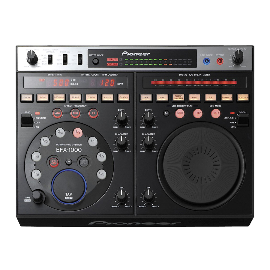
Page 98: Panel Facilities
BOTH: Both [INPUT] and [OUTPUT] indicators light. Attached foot switch controls both beat effect function and Input stereo display: digital jog break function (ON/OFF). [INPUT] and [L], [R] indicators light. Output stereo display: [OUTPUT] and [L], [R] indicators light. EFX-1000... - Page 99 (effects are locked ON). When pulled to the [ON] position, Lights during normal use; goes out only when TAP is beat effects are output only while the lever is held; when pressed. your finger is released, the lever returns to middle [OFF] position. EFX-1000...
- Page 100 8 seconds. Recording to memory is not possible during jog During operation of the Jog dial, and during jog memory memory play. play, this meter lights to display the corresponding movement. EFX-1000...
-
Page 101: Connection Panel
[Example of connections that must not be performed] 8 Input/output gain select switch (IN&OUT LEVEL) Use to select the input/output gain (–10dB / +4dB). (default : –10dB) EFX-1000... -
Page 102: Jigs List
Refer to 7.1.2 REWRITING THE FIRMWARE. PC (Windows 98, XP, 2000) About these softwares (Flash Development Tool kit and Program Flash Files) Flash Development Tool Kit (ver. 3.3) To obtain these software, contact your nearest Pioneer service Program Flash File center. EFX-1000...
Need help?
Do you have a question about the EFX-1000 and is the answer not in the manual?
Questions and answers