Table of Contents
Advertisement
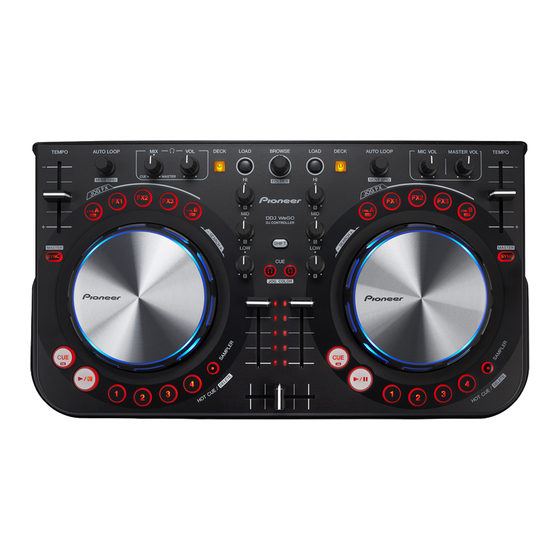
DJ CONTROLLER
DDJ-WEGO-K
THIS MANUAL IS APPLICABLE TO THE FOLLOWING MODEL(S) AND TYPE(S).
Model
Type
XE5
DDJ-WEGO-K
XECN5
XE5
DDJ-WEGO-W
XECN5
DDJ-WEGO-V
XE5
DDJ-WEGO-G
XE5
XE5
DDJ-WEGO-R
XECN5
PIONEER CORPORATION
PIONEER ELECTRONICS (USA) INC. P.O. Box 1760, Long Beach, CA 90801-1760, U.S.A.
PIONEER EUROPE NV Haven 1087, Keetberglaan 1, 9120 Melsele, Belgium
PIONEER ELECTRONICS ASIACENTRE PTE. LTD. 253 Alexandra Road, #04-01, Singapore 159936
PIONEER CORPORATION
Power Requirement
DC 5 V (USB-bus power only)
1-1, Shin-ogura, Saiwai-ku, Kawasaki-shi, Kanagawa 212-0031, Japan
2012
DDJ-WEGO-K
K-MZV OCT.
ORDER NO.
RRV4381
Remarks
2012 Printed in Japan
Advertisement
Table of Contents

Related Manuals for Pioneer DDJ-WEGO-K


Summary of Contents for Pioneer DDJ-WEGO-K
- Page 1 PIONEER CORPORATION 1-1, Shin-ogura, Saiwai-ku, Kawasaki-shi, Kanagawa 212-0031, Japan PIONEER ELECTRONICS (USA) INC. P.O. Box 1760, Long Beach, CA 90801-1760, U.S.A. PIONEER EUROPE NV Haven 1087, Keetberglaan 1, 9120 Melsele, Belgium PIONEER ELECTRONICS ASIACENTRE PTE. LTD. 253 Alexandra Road, #04-01, Singapore 159936...
-
Page 2: Safety Information
WARNING This product may contain a chemical known to the State of California to cause cancer, or birth defects or other reproductive harm. Health & Safety Code Section 25249.6 - Proposition 65 DDJ-WEGO-K... -
Page 3: Table Of Contents
11. PCB CONNECTION DIAGRAM ............................48 11.1 CONTROL PCB ASSY ............................... 48 11.2 IO PCB ASSY ................................52 11.3 MASTER PCB ASSY..............................54 11.4 WHELL (R) PCB ASSY .............................. 55 11.5 WHEEL (L) PCB ASSY............................... 56 12. PCB PARTS LIST ................................57 DDJ-WEGO-K... -
Page 4: Service Precautions
10 minutes, or press the DECK C/D button while pressing the SHIFT button, Demonstration mode with lighting of the LEDs on the JOG dial is automatically entered. To return to the normal operation mode, operate any button other than the SHIFT or DECK C/D buttons or JOG dial or operate any control of this unit. DDJ-WEGO-K... -
Page 5: Specifications
Stereo phone jack (Ø 6.3 mm) ..........1 set Stereo mini phone jack (Ø 3.5 mm)........1 set MIC input terminal Phone jack (Ø 6.3 mm)............1 set For improvement purposes, specifications and design of this unit and the included software are subject to change without notice. DDJ-WEGO-K... -
Page 6: Basic Items For Service
Purpose of use / Remarks USB cable GGP1193 for PC connection Lubricants and Glues List Name Part No. Remarks Grease PS-70 Refer to “7. DISASSEMBLY”. DAIZO NICHIMOLY NEW-SL PS-70 Adhesive GYL1001 Refer to “7. DISASSEMBLY”. Adhesive GYL1005 Refer to “7. DISASSEMBLY”. DDJ-WEGO-K... -
Page 7: Pcb Locations
Therefore, when replacing, be sure to use parts of identical designation. Mark No. Description Part No. LIST OF ASSEMBLIES 1..CONTROL PCB ASSY 704-DDJLE-A368 1..IO PCB ASSY 704-DDJLE-A367 1..MASTER PCB ASSY 704-DDJLE-A372 1..WHEEL (R) PCB ASSY 704-DDJLE-A370 1..WHEEL (L) PCB ASSY 704-DDJLE-A371 DDJ-WEGO-K... -
Page 8: Block Diagram
4. BLOCK DIAGRAM 4.1 OVERALL WIRING DIAGRAM WHEEL (L) PCB ASSY (704-DDJLE-A371) CN01B CN02B CONTROL PCB ASSY (704-DDJLE-A368) CN01A CN02A W01A CN605 W01B W604 W02A W02B CN502 CN501 W502 W501 CN604 CN605A MASTER PCB ASSY IO PCB ASSY (704-DDJLE-A372) (704-DDJLE-A367) DDJ-WEGO-K... - Page 9 404-DDJLE-3772 W 01A to 01B, 02A to 02B 404-DDJLE-3721 WIRE HARNESS CHASSIS 1/2 WIRE 406-DDJLE-1229 R PCB ASSY WIRE 406-DDJLE-1230 G 1A to 1B WIRE 406-MX200-1110 JLE-A372) W 3A to 3B WIRE 406-DDJLE-1237 W 4A to 4B WIRE 406-H464-020 DDJ-WEGO-K...
-
Page 10: Overall Block Diagram
4.2 OVERALL BLOCK DIAGRAM IO PCB ASSY IC501 USB Controller TUSB3200 6.5V 65mA DC/DC 70mA USB5V DC/DC POWER SW. 485mA 3.3V Power Consumption DC/DC DDJ-WEGO-K... - Page 11 LM4917 4580 4.7 OHM PCM1754 70mA CONTROL PCB ASSY INDICATORS LED KEYS & ENCODER VR & FADERS DIP RED LED 7.2mcd DRIVER WHEEL LED 3020 SMD RED LED 36~45mcd RGB LED --->RED 50~100mcd USB_Vcc_AD_PORT IC600 UI CPU STM8S207MB WHEEL DDJ-WEGO-K...
-
Page 12: Diagnosis
5. DIAGNOSIS 5.1 BOOT SEQUENCE START CPU BOOT (TUSB3200) Press specia1 or updata error ? UPDATA CODE Success CPU RUN CODE (TUSB3200) (KEY & FADER & SIDER & JOG dial) start operator DDJ-WEGO-K... -
Page 13: Troubleshooting
Step 3: IC200 Pin 13 MD (waveform ), IC200 Pin 14 MC (waveform ), IC200 Pin 15 ML1 (waveform CHECK Analog Audio Signal Line Step 4: IC201 Pin 7/1 (waveform ), IC202 Pin 7/1 (waveform Step 5: CN501 Pin 1/3 (waveform DDJ-WEGO-K... - Page 14 Step 1: VR Power Voltage 5 V (waveform CHECK Digital Control Signal Step 2: IC600 Pin 68 SDA Waveform (waveform [10] Each operation doesn’t linked with PC CHECK Digital Control Signal Step 1: POWER ON SDA Waveform (waveform 10-1 DDJ-WEGO-K...
-
Page 15: Operation Check With Virtual Dj
If the OS of the PC is Windows, the driver software for outputting audio from the PC must be installed beforehand. The requirements of a PC on which VIRTUAL DJ LE can be installed are as shown below. [Connections] etc. DDJ-WEGO-K... - Page 16 The Settings window is displayed. Select the Sound Setup tab and set the following items in the order described below. 1 [Inputs]: Select NONE. 2 [Sound card]: Select ASIO DRIVER and Pioneer DDJ_WeGO ASIO. 3 [Outputs]: Select HEADPHONE and [Master: Chan 1&2/Headphones: Chan 3&4].
-
Page 17: Service Mode
The mode which returns the item where user setting is possible for the setting of the factory shipping state 5 VOLUME VALUE FLUCTUATION CONFIRMATION MODE The mode which measures fluctuation of voltage (A/D conversion value) that you acquired from each fader and rotary volume * These modes will not do TUSB communication. DDJ-WEGO-K... -
Page 18: Firmware Version (Main Ucom) And Last Memory Confirmation Mode
[Numerics expressed with the number of lit LEDs] (LED on DECK D lit) X.XX 3 ms 4 ms 5 ms 6 ms 7 ms 8 ms 9 ms 10 ms 11 ms 12 ms 13 ms [Numerics expressed with the number of lit LEDs] DDJ-WEGO-K... - Page 19 [HOT CUE3] button on the right deck Sensitivity: +3 [HOT CUE4] button on the right deck Sensitivity: +4 (high) Illumination mode Headphone [CUE] button Pulse Mode: Active Both headphone [CUE] buttons will be lit. Pulse Mode: Normal Both headphone [CUE] buttons will be lit off. DDJ-WEGO-K...
-
Page 20: Button Input And Display Function Confirmation Mode
JOG ROTATION DIAL JOG LED ROTATION B JOG TOUCH DIAL JOG LED ALL ON CTRL A BUTTON CTRL A FX 1 BUTTON FX 1 FX 2 BUTTON FX 2 FX 3 BUTTON FX 3 CTRL B BUTTON CTRL B DDJ-WEGO-K... - Page 21 Brightness will be adjusted as standard brightens. At the minimum volume, LEDs 12, 13, and 14 are lit. The lighting LEDs shift as the volume is increased, and LEDs 3, 4, and 5 are lit at the maximum volume. Brightness will be adjusted as standard brightens. DDJ-WEGO-K...
- Page 22 When touched jog dial, all LED on jog dial turn on. LED of jog dial doesn't turn on in case of turning jog dial. When jog dial is turned with touched jog dial platter, 3LED of jog dial turns. DDJ-WEGO-K...
-
Page 23: Jog Dial Rotation Time Measurement Mode
*2: You correspond both of clockwize and counter clockwize. 2 The controller measure T1 below. *T1: The time that Jog rotation speed slow down from 100 rpm to 50 rpm. XXXms 2 sec XXXms 2 sec 2 sec XXXms [Numerics expressed with the number of lit LEDs] DDJ-WEGO-K... -
Page 24: Factory Reset Mode
Note: If this setting is not performed, the color of the RGB LEDs of the jog dials for all the decks will be set to blue when the unit is turned ON for the next time. Color Variation on Controller Default Color (LED) Setting Button Black (DDJ-WEGO-K) Blue CTRL A Red (DDJ-WEGO-R) Orange... -
Page 25: Volume Value Fluctuation Confirmation Mode
Right deck, HOT CUE 1 LED Right deck, EQ (HI) control Right deck, HOT CUE 2 LED Right deck, MASTER VOL control Right deck, HOT CUE 4 LED Right deck, TEMPO slider Right deck, SAMPLER LED Crossfader Left, Right deck, HEADPHONES CUE LED DDJ-WEGO-K... - Page 26 5. More time has elapsed, To maintain the above display 762 even though the value of the A / D. 10. Off all the Channel level indicator when you push the Rotary selector, and this value will be new reference value. DDJ-WEGO-K...
-
Page 27: Disassembly
(602-SL24F-099) (3) Disconnect the one flexible cable. (CN605A) CN605A (2) Remove the IO PCB Assy with plate by removing the four screws. (602-SL24F-099) Screw tightening order MASTER PCB Assy IO PCB Assy • Bottom view DDJ-WEGO-K... - Page 28 (CN01A, CN02A) CN02A CN01A • Bottom view (4) Remove the two WHEEL Assemblies. WHEEL Assy WHEEL Assy (5) Remove the WHEEL (L) and (R) PCB WHEEL (L) PCB Assy WHEEL (R) PCB Assy Assemblies by removing the six screws. (602-SL24F-099) DDJ-WEGO-K...
- Page 29 (2) Disconnect the two flexible cables. CONTROL PCB Assy (CN01A, CN02A) ×39 (3) Remove the CONTROL PCB Assy by removing the 39 screws. (602-SL24F-099) Screw tightening order The other screws are random order. CN02A CN01A • Bottom view CONTROL PCB Assy DDJ-WEGO-K...
- Page 30 The Application Position of Adhesive and Grease WHEEL Assy Grease Adhesive (PS-70) (GYL1001) Cushion Cushion Cushion • Bottom view Grease Grease (PS-70) (PS-70) • Bottom view Cushion Adhesive (GYL1001) MASTER PCB Assy IO PCB Assy Chassis Assy Adhesive (GYL1005) Sponge Sponge DDJ-WEGO-K...
-
Page 31: Each Setting And Adjustment
PC, Click "OK", finish the Firmware 3 Click "Start" to update procedure, the information with PC. update. * When update fails, all level indicators blink when a power is turned on. In that case, please update it again. DDJ-WEGO-K... -
Page 32: Items For Which User Settings Are Available
Content to be Part Name Setting is Available settings are indicated in bold.) Stored Color of the jog dial’s illumination CONTROL PCB ASSY (704-DDJLE-A368) Setting coller Blue (DDJ-WEGO-K) [NSP] STM8S207MB Control IC (IC600) Frosty white (DDJ-WEGO-W) Orange (DDJ-WEGO-R) Emerald green (DDJ-WEGO-G) Violet... - Page 33 DDJ-WEGO-K...
-
Page 34: Exploded Views And Parts List
Screws adjacent to b mark on product are used for disassembly. For the applying amount of lubricants or glue, follow the instructions in this manual. (In the case of no amount instructions, apply as you think it appropriate.) 9.1 PACKING SECTION Warranty card DDJ-WEGO-K... - Page 35 8 Polyfoam R 506-DDJLE-646R 9 Gift Box See Contrast table (2) 10 Soft Bag 509-DDJLE-318 (2) CONTRAST TABLE DDJ-WEGO-K/XE5, DDJ-WEGO-K/XECN5, DDJ-WEGO-W/XE5, DDJ-WEGO-W/XECN5, DDJ-WEGO-V/XE5, DDJ-WEGO-G/XE5, DDJ-WEGO-R/XE5 and DDJ-WEGO-R/XECN5 are constructed the same except for the following: DDJ-WEGO-K DDJ-WEGO-K DDJ-WEGO-W DDJ-WEGO-W Mark...
-
Page 36: Exterior Section
9.2 EXTERIOR SECTION SN label Bar code DDJ-WEGO-K... - Page 37 33 L Output Fixed Plate 300-DDJLE-2030 34 R Output Fixed Plate 300-DDJLE-2031 35 Large Ground Plate 300-DDJLE-2055 (2) CONTRAST TABLE DDJ-WEGO-K/XE5, DDJ-WEGO-K/XECN5, DDJ-WEGO-W/XE5, DDJ-WEGO-W/XECN5, DDJ-WEGO-V/XE5, DDJ-WEGO-G/XE5, DDJ-WEGO-R/XE5 and DDJ-WEGO-R/XECN5 are constructed the same except for the following: DDJ-WEGO-K DDJ-WEGO-K DDJ-WEGO-W DDJ-WEGO-W Mark...
-
Page 38: Schematic Diagram
C114EK A C114EK A C114EK A C114EK A C114EK A C114EK A C114EK A PLAY- A D606 D613 D620 1SS355 1SS355 1SS355 K R7 SW614 SW621 SW607 SAMP LER- B DECK -A CUE- A D607 D614 D621 1SS355 1SS355 1SS355 DDJ-WEGO-K... - Page 39 D630 SHCP 1 R895 1SS355 1SS355 1SS355 1SS355 2SC2712GR SW614 SW621 SW628 SW629 R951 SAMP LER- B JFX2- B LOAD- A PWM2 DECK -A C897 C895 Q606 220P D614 D621 D628 D629 220P 220P 1SS355 1SS355 1SS355 1SS355 C896 DDJ-WEGO-K...
-
Page 40: Io And Master Pcb Assys
RTR030P 02 10/25 0.1uF 10/25 TP S54232 100uH/0.2A C124EK A BOOT SM5819A 22uH/1.11A VI N 5.1K COMP 1.2K IC10 VSNS 10/25 BOOT SM5819A VI N COMP 1200P 4.7/16(NC) VSNS 0.015u 1000P TP S54232 48.7K 270P 6.2K 0.015u BEAD(65 OHM) DDJ-WEGO-K... - Page 41 Av =2.47dB@4.7V Av =2.5dB Av =-1.157dB BEAD(65 OHM) BA05F P L62 BEAD(65 OHM) 2-13 C63 22/25 C124EK A /INT /REST PMUTE CN605 DMUTE USB5V CON10 CN605A 6.5V 3.3uH 3.3V 10/25 SM5819A CN502 -6.5V 3.24K W502 1000P CON4 1-2 8-2 DDJ-WEGO-K...
-
Page 42: Whell (R) And (L) Pcb Assys
D640 D639 D675 D683 D676 D682 D677 D681 VER0.42 D641 D642 CHANGE R942/941/940/939/938/937/948/947/946/945/ CHANGE R928/929/930/925/990/927/934/935/936/931/ CHANGE R916/917/918/919/920/921/922/923/924/913/ CHANGE R907/908/909/910/911/912/987/988/989/904/ D678 VER0.43 CHANGE R982/984 1K D680 CHANGE R986/688 1K D679 VER 0.44 CHANGE R992 10K -->100K CHANGE R991 10K -->100K DDJ-WEGO-K... - Page 43 D645 LEDRGBGG D646 D667 D668 D666 D637 D638 D665 D669 D664 D670 D663 D671 /940/939/938/937/948/947/946/945/944/943 1.8K D636 D635 9/930/925/990/927/934/935/936/931/932/933 1.8K 7/918/919/920/921/922/923/924/913/914/915 1.8K -->1K 8/909/910/911/912/987/988/989/904/905/906 1.8K -->510 -->1K 4 1K -->510 D662 8 1K D660 D661 K -->100K K -->100K DDJ-WEGO-K...
-
Page 44: Waveforms
SCK (IC200 Pin 16) IC315 ADC -> Pin 11(BCK) 2-10 3.3 V (C17 + side) CSCLK (IC501 Pin 34) SCK (IC300 Pin 16) INPUT (JK101) 2-11 MCLKO (IC501 Pin 44) BCK (IC200 Pin 1) BCK (IC300 Pin 1) MASTER OUT (JK102) DDJ-WEGO-K... - Page 45 BCK (IC200 Pin 1) MC (IC200 Pin 14) -6.5 V (IC201/202 Pin 4) MD (IC200 Pin 13) SDO1 (IC200 Pin 2) ML1 (IC200 Pin 15) BCK (IC200 Pin 1) MC (IC200 Pin 14) LRCK (IC200 Pin 3) (IC201/202 Pins 7/1) DDJ-WEGO-K...
- Page 46 LRCK (IC300 Pin 3) 3.3 V (IC302 Pins 2/9 ) MD (IC300 Pin 13) -6.5 V (IC301 Pin 4) SCK (IC300 Pin 16) BCK (IC300 Pin 1) MC (IC300 Pin 14) 3.3 V (IC302 Pins 2/9) MD (IC300 Pin 13) DDJ-WEGO-K...
- Page 47 OE (IC607/608 Pin 13) 7-11 (IC302 Pin 8) 3.3 V (C17 + side) VR Voltage 7-12 R/L (JK301/302) 5 V (IC607/608 Pin 16) SDA (IC600 Pin 68) 10-1 5 V (JK501 Pin 1) SHCP (IC607/608 Pin 11) POWER ON SDA DDJ-WEGO-K...
-
Page 48: Pcb Connection Diagram
11. PCB CONNECTION DIAGRAM 11.1 CONTROL PCB ASSY SIDE A CONTROL PCB ASSY DDJ-WEGO-K... - Page 49 NOTE FOR PCB DIAGRAMS : Connector Capacitor 1. The parts mounted on this PCB include all necessary parts for several destinations. SIDE A For further information for respective destinations, be sure to check with the schematic diagram. SIDE B P.C.Board Chip Part DDJ-WEGO-K...
- Page 50 SIDE B CONTROL PCB ASSY CN02B Q801 Q805 IC601 Q809 IC602 IC600 IC611 Q803 Q807 Q811 Q813 Q817 Q821 IC603 Q603Q606 IC608 Q819 Q604 DDJ-WEGO-K...
- Page 51 SIDE B CN605A CN605 CN01B 8-6 8-7 IC600 IC609 Q837 Q835 IC604 Q827 Q831 Q602 Q825 Q829 IC618 Q601 IC610 IC502 Q605 Q833 IC606 Q845 IC607 IC605 Q841 Q843 DDJ-WEGO-K...
-
Page 52: Io Pcb Assy
11.2 IO PCB ASSY SIDE A IO PCB ASSY 2-2 2-3 7-12 7-12 2-11 2-12 2-13 2-10 6-10 6-6 6-7 7-10 7-5 7-6 7-7 SIDE B 7-11 6-11 6-3 7-3 6-1 7-1 6-2 7-2 IO PCB ASSY 4-10 DDJ-WEGO-K... - Page 53 SIDE A W502 W501 IC200 IC501 IC10 IC300 CN605 6-10 7-10 SIDE B Q207 IC302 Q208 Q203 IC301 Q211 Q204 Q210 1-4 8-4 IC201 4-10 4-10 DDJ-WEGO-K...
-
Page 54: Master Pcb Assy
11.3 MASTER PCB ASSY SIDE A SIDE A MASTER PCB ASSY CN502 CN501 W604 SIDE B SIDE B MASTER PCB ASSY IC100 IC101 Q209 Q202 Q206 IC202 Q205 Q201 4-10 4-10 DDJ-WEGO-K... -
Page 55: Whell (R) Pcb Assy
11.4 WHELL (R) PCB ASSY SIDE A SIDE A WHEEL (R) PCB ASSY IC616 CN02B CN02A IC617 IC615 SIDE B SIDE B WHEEL (R) PCB ASSY CN02B DDJ-WEGO-K... -
Page 56: Wheel (L) Pcb Assy
11.5 WHEEL (L) PCB ASSY SIDE A SIDE A WHEEL (L) PCB ASSY IC613 IC614 CN01A CN01B IC612 SIDE B SIDE B WHEEL (L) PCB ASSY CN01B DDJ-WEGO-K... -
Page 57: Pcb Parts List
403-MC2-383 L 1,2,61,62 BEAD 415-DCM370E3-134 W 3A to 3B WIRE 406-DDJLE-1237 L 301,302 INDUCTOR 415-CDMIX1-139 W 4A to 4B WIRE 406-H464-020 CN 01A,02A 10P 1.0 FFC SOCKET 404-PDJ22-3567 G 1A to 1B WIRE 406-MX200-1110 JK 501 GR0UND PLATE 300-1000-1908 DDJ-WEGO-K... - Page 58 413-CDVD2001-265 WHEEL (R) PCB ASSY SEMICONDUCTORS IC 615-617 IC 417-DDJLE-1080 D 651,652 SENSOR 417-HDJ2000-411 MISCELLANEOUS CN 02B FFC CABLE 406-DDJLE-1226 WHEEL (L) PCB ASSY SEMICONDUCTORS IC 612-614 IC 417-DDJLE-1080 D 653,658 SENSOR 417-HDJ2000-411 MISCELLANEOUS CN 01B FFC CABLE 406-DDJLE-1226 DDJ-WEGO-K...
Need help?
Do you have a question about the DDJ-WEGO-K and is the answer not in the manual?
Questions and answers