Coway CHP-06DL Service Manual
Hide thumbs
Also See for CHP-06DL:
- Installation manual (44 pages) ,
- User manual (32 pages) ,
- User manual (32 pages)
Table of Contents
Advertisement
Advertisement
Table of Contents

Related Manuals for Coway CHP-06DL


Summary of Contents for Coway CHP-06DL
-
Page 3: Table Of Contents
Table of Contents 1. Precaution 1-1 Precautions on electricity ................1-2 Precautions on installation ................1-3 Precautions on use ..................1-4 Precautions on services ................. 2. Product characteristics and specifications 2-1 Product characteristics ................... 2-1-1 Product characteristics ................ 2-1-2 Characteristics of major parts .............. 2-2 Major specifications .................. - Page 4 5-2-1 Basic specifications ................5-2-2 Major functions ..................6. Exploded view of the system and the list of service parts 6-1 Exploded view and parts list of CHP-06DL ............ 6-2 Service parts list of CHP-06DL ..............7. Parts location diagrams 7-1 Electrical wiring diagram ................
-
Page 5: Precaution
- Otherwise electric shock or fire may occur as a result. 11. If the electric outlet is wet, carefully unplug the unit and let the electric outlet completely dry before subsequent use. - Otherwise electric shock or fire may occur as a result. Coway co., Ltd... -
Page 6: Precautions On Installation
- If it is longer, it may degrade the product’s performance, and prevent complete drainage of water. 6. Proper places to install the unit - Install the unit firmly on a level area. If the unit is installed in an unstable place, the system may not function properly. Coway co., Ltd... -
Page 7: Precautions On Use
8. When cleaning the water storage tanks, drain the water (cold/hot/room temperature water) from the tanks through extraction cock. Open the side drain door and then drain the water still remaining in the hot water tank. Coway co., Ltd... -
Page 8: Precautions On Services
- Otherwise, product malfunction, short circuit, or fire may occur as a result. 3. Connect the electricity and check that the unit operates properly before let the consumer use the product. - Make sure to inform the consumer of the malfunction and repair details. Coway co., Ltd... -
Page 9: Product Characteristics And Specifications
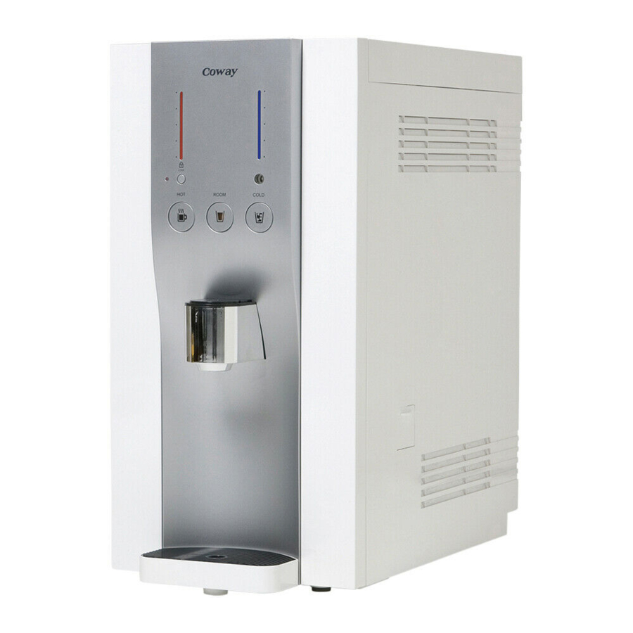
Display window showing the product conditions at a glance - A display window shows mode status (cold-water /hot-water modes) at a glance, enabling easy confirmation. Coway co., Ltd... -
Page 10: Characteristics Of Major Parts
AMPS: 210mA Volts: DC 24V N.O.S Valve AMPS: 210mA Fuse 250V~ / 6.3A Compressor 1/12 HP, 220V~ / 50Hz Heater 300W, 220V~ / 50Hz Possible manual reset Bi-Metal OFF: 88°C, ON: manual reset temperature: 84°C or lower Coway co., Ltd... -
Page 11: Major Specifications
76.8 L/day (25°C, 20psi) Product dimensions 260 (width) x 440 (depth) x 510 (height) mm Product weight 18.7kg There may be some discrepancies in the actual water-purifying quantity depending on the water temperature in season (Spring/fall, summer, and winter). Coway co., Ltd... -
Page 12: Appearance And Dimensions
Product characteristics and specifications 2-3 Appearance and dimensions CHP-06DL [260 (width) x 440 (depth) x 510 (height) mm] Coway co., Ltd... -
Page 13: Product Installation
Product installation 3. Product installation 3-1 Installation materials 3-1-1 Parts Accessories Items Remark Drain hose Cooling Stopper Coway co., Ltd... -
Page 14: Installation Method
8 inch (S) for about 3 minutes. (Water flow rate 300~500㎖/min) - Separate the Post Carbon block filter 8 inch (S) from the Neo Sense filter 8 inch (S) and then connect it to the bottom of the Membrane filter (RO) 8 inch. Coway co., Ltd... -
Page 15: Installing The Product
Product installation 3-2-2 Installing the product Cooling stopper Main water supply valve Inlet tubing (Orange) Outlet tubing (Blue) Coway co., Ltd... - Page 16 Flush water through each filter at least 5 minutes before connection. 1) Connect it to voltage rating that matches it on the rating plate. Then, open the feed valve to supply water to the filtration system. PLUG Coway co., Ltd...
-
Page 17: Checking The System After Installation
1) To drink room water, select the room button. - Select the room water button and touch the extraction part, and you can extract a cupful of water. If you touch the extraction part again during extraction, water stops flowing. Coway co., Ltd... - Page 18 If you touch the extraction part again during extraction, the water stops flowing. 1) Empty the gutter periodically. - Prevent water overflowing from the water receptacle by periodically emptying it. Coway co., Ltd...
-
Page 19: Disassembling And Refitting
Exercise caution not to damage or deform any parts when disassembling the system. Refit the system in the reverse order of disassembling. 4-1-2 Necessary tools Tool Tool name ‘+’ Cross-head screwdriver ‘-’ Flat-bladed screwdriver Nipper Adjustable spanner Coway co., Ltd... -
Page 20: Draining Water Before Disassembling The Product
4-2 Draining water before disassembling the product 4-2-1 Draining Part name Explanation Reference picture Drain 1) Open the drain door and connector separate the drain connector cap. Drain hose 1) Connect the drain hose and then drain the hot water. Coway co., Ltd... - Page 21 Disassembling and refitting Part name Explanation Reference picture Drain hose 1) Connect the drain hose to the 3-way valve cock. 2) Touch the extraction button and drain the water completely. Coway co., Ltd...
-
Page 23: Separating The Front Cover Part (1)
3) Separate the 2 connectors connected to the front cover assy. Front PBA 1) Separate the connector connected to the front deco. 2) Remove the 4 screws and separate the front PBA. : 4-4x12 TAP Coway co., Ltd... - Page 24 2) Remove the switch knob. 1) Remove the 2 screws from both Cock deco sides of the front deco. assy : 2-4x12 TAP 2) Remove the front deco by pressing both sides of it hard in the direction of the arrows. Coway co., Ltd...
- Page 25 Disassembling and refitting Part name Explanation Reference picture Front deco 1) Open the front deco in the direction of the arrows. 2) Separate the front deco PBA. Coway co., Ltd...
-
Page 26: Separating The Side L/R Cover Parts
3) Remove the 2 screws from the side L cover assy. : 2-4x12 TAP 4) Remove the 6 screws from the rear cover. : 6-4x12 TAP 5) Remove the 6 screws from the frame. : 6-4x12 TAP Coway co., Ltd... - Page 27 6) Separate the side L cover. 7) Separate the side R cover. Filter 1) Remove the fittings connected to each filter. 2) Remove filters. Auto daily 1) Separate the auto daily life water life water controller from the Membrane controller filter. Coway co., Ltd...
- Page 29 1) Remove the 2 screws from the assy 3-way valve and cut 2 cable ties and remove 2 band ties from the silicon hoses. : 2-4x12 TAP - 2) Separate the 2 silicon hoses connected to each tank. Coway co., Ltd 4-11...
- Page 30 PBA with the water remaining in the tank. Cold water 1) Remove the tape and separate thermistor the press sealant. 2) Remove the 2 screws and separate the thermistor. : 2-4x12 TAP Coway co., Ltd 4-12...
- Page 31 Bimetal 1) Separate the 2 connectors connected to the bimetal from the bottom of the hot water tank. 2) Separate the bimetal by removing the 2 nuts. Coway co., Ltd 4-13...
-
Page 33: Fault Diagnosis
FND cable connection Check the FND cable and connection cable open? is faulty. replace it if necessary. Is the PCB power circuit Check the main PCB and voltage of the PCB micom defect. replace it if necessary. DC 5V? Coway co., Ltd... - Page 34 2) Cold water temperature 7.3°C or higher When the compressor is in operating conditions, is the The main PCB is Check the main compressor power supply of abnormal. PCB and replace it if AC 220V generated? necessary. Coway co., Ltd...
- Page 35 Is the heater If the measurement value resistance value rated Replace the heater. is off the specification, the value (30.3~37Ω)? heater is faulty. Is the PCB Check the PCB and voltage AC 220V? replace it if necessary. Coway co., Ltd...
- Page 36 FND? Replace them if necessary. Water level sensor error: The heater and compressor are turned off. When the power is turned off and then on again, the system returns to normal operation. Coway co., Ltd...
-
Page 37: Control Specifications
Fault diagnosis 5-2 Control specifications Water overflow sensor Hot water tank Reed level sensor Cold water thermistor 3WAY V/V Main PBA FEED+NOS Valve Coway co., Ltd... -
Page 38: Basic Specifications
Fault diagnosis 5-2-1 Basic specifications 1. Scope of application This control specification is for the electronic control devices applied to Coway’s household cold/hot water purification system (CHP-06DL). 2. Operating conditions 1) Power: AC 220V~, 50Hz 2) Surrounding temperature: -20°C - +70°C (storage), 0°C - +50°C (use) - Page 39 7 Cold water LED 8 Extraction indicator LED 2 Operation Part 1 Hot water lock button 2 Hot water button 3 Room water button 4 Cold water button 5 Extraction cock 6 Cold/hot/room temperature water Extraction button Coway co., Ltd...
-
Page 40: Major Functions
Operation alarm bell Bell status. The extraction valve used when to Extraction valve 3-WAY V/V extract the selected cold/hot/room temperature water. Feed water valve FEED V/V A feed water inlet valve. NOS valve NOS V/V A safety shut-off valve. Coway co., Ltd... - Page 41 When the power is turned off and then on again during normal operation, the previous setting is maintained. Whe the power is connected for the first time, basically all functions are set OFF. After checking the stored values on the EEPROM, input and output are set. Coway co., Ltd...
- Page 42 - The compressor is always off regardless of the low/full water level sensor status and cold water sensor values. 3) When the cold water function is turned on, the cold water temperature indicator LED is turned on regardless of the low/full water sensor status. 5-10 Coway co., Ltd...
- Page 43 3) When the cold water sensor is OPEN or SHORT, the temperature is detected 100 times at an interval of 10 ms. When the sensor returns to a normal status, the normal operation resumes. 7. Overcooling (Cold water temperature 1°C or lower) 1) When the water is overcooled, the compressor is turned off. Coway co., Ltd 5-11...
- Page 44 3) Hot water mode ON when the low water level sensor is in SHORT status (low water level sensor detection) - The heater operates in a normal condition according to the hot water sensor values. 5-12 Coway co., Ltd...
- Page 45 99°C or higher (13.872 K Ω overheated. - When restarting, the heater and the hot Restart 96°C or lower (15.276 water lamp operate in a normal condition K Ω according to the hot water sensor values. Coway co., Ltd 5-13...
- Page 46 1) Low/full water level sensor OPEN/SHORT operation is recognized - When the same status is detected continuously for 4 seconds. Full water Full water Full water levelOPEN levelSHORT levelOPEN Low water Low water Low water levelOPEN levelSHORT levelSHORT Water Water overflowSHORT 0 overflowOPEN 0 5-14 Coway co., Ltd...
- Page 47 1. When the sensing area detects 1.2 +/-15%pF or higher, extraction 18mm operates. (Electrostatic capacity 4pF ~ 20pF) 2. Extraction starts 100ms after the human body contacts the sensing area (when the condition 1 above is met). 18mm Non-sensing area Coway co., Ltd 5-15...
- Page 48 Flsahes at an interval of 100ms from 1.4 seconds before completing extraction. Extraction switch should be re-entered (150ms) or it goes off after extracting water for 60 seconds. The extraction switch is recognized 500ms after it is turned off. 5-16 Coway co., Ltd...
- Page 49 Flsahes at an interval of 100ms from 1.4 seconds before completing extraction. Extraction switch should be re-entered (150ms) or it goes off after extracting water for 60 seconds. The extraction switch is recognized 500ms after it is turned off. Coway co., Ltd 5-17...
- Page 50 Extraction switch should be re-entered (150ms) or it goes off after extracting water for 60 seconds. If ther is no additional extraction for 5 seconds after the extraction, it switches to cold water mode. 5-18 Coway co., Ltd...
- Page 54 Extraction V/V ON_TIME (sec) Low water full water Room temperature Cold display level sensor level sensor water water water OPEN OPEN 14.5 12.6 13.8 Extraction 3 SHORT OPEN 13.4 11.9 13.2 -300cc- SHORT SHORT 11.6 12.7 5-22 Coway co., Ltd...
- Page 55 TIME_TABLE when the power is turned off and then on again or the room temperature selection switch is pressed for 3 seconds. 4) When the system is in the function setting mode, the current setting status is displayed. (EEPROM saved) Coway co., Ltd 5-23...
- Page 56 94.521 144.354 124.827 108.236 11.4 94.084 143.650 124.230 107.727 11.5 93.649 142.949 123.636 107.221 11.6 93.217 142.253 123.045 106.718 11.7 92.786 141.560 122.457 106.217 11.8 92.359 140.871 121.873 105.719 11.9 91.933 140.186 121.291 105.224 12.0 91.509 5-24 Coway co., Ltd...
- Page 57 66.7 42.112 69.7 37.718 72.7 33.833 60.8 52.540 63.8 46.914 66.8 41.956 69.8 37.580 72.8 33.712 60.9 52.340 63.9 46.739 66.9 41.802 69.9 37.444 72.9 33.591 61.0 52.142 64.0 46.564 67.0 41.647 70.0 37.307 73.0 33.470 Coway co., Ltd 5-25...
- Page 58 92.7 17.011 95.7 15.426 98.7 14.006 86.8 20.702 89.8 18.723 92.8 16.956 95.8 15.376 98.8 13.961 86.9 20.632 89.9 18.661 92.9 16.900 95.9 15.326 98.9 13.917 87.0 20.563 90.0 18.599 93.0 16.845 96.0 15.276 99.0 13.872 5-26 Coway co., Ltd...
- Page 59 MEMO Coway co., Ltd 5-27...
-
Page 60: Exploded View Of The System And The List Of Service Parts
6. Exploded view of the system and the list of service parts 6-1 Exploded view and parts list of CHP-06DL This document is Coway’s technical property. Only the person approved by the company may use this document. Coway co., Ltd... - Page 61 MAIN TANK CAP ASSY FILTER COVER ASSY TOP COVER ASSY FRAME TRAY ASSY FEED NOS VALVE ASSY MAIN PBA ASSY 3WAY VALVE ASSY HEATING TANK ASSY MAIN TANK ASSY COOLING TANK INSULATION FRONT COOLING TANK INSULATION REAR Coway co., Ltd...
-
Page 62: Service Parts List Of Chp-06Dl
Exploded view of the system and the list of service parts 6-2 Service parts list of CHP-06DL Code No. Description Specification Q’ty Remark POST-CARBON FILTER-BLOCK 110244 8INCH 8INCH(S) 110207 MEMBRANE FILTER-RO 8INCH(S) 8INCH, 20GPD 110245 NEOSENSE FILTER-8INCH(S) 8iNCH 3106863 BASE ASSY(CHP-06DL) - Page 63 3106029 SEPARATOR BOARD (CHP-06DL) JI360 - 3685T 3106030 REAR COVER ASSY (CHP-06DL) 3106876 MAIN PBA COVER ASSY 3106032 SIDE COVER R ASSY (CHP-06DL) 3106033 SIDE COVER L ASSY 3106034 SIDE DOOR ASSY (CHP-06DL) 3107912 FRONT COVER ASSY (CHP-06DL) 3207663 FRONT DECO (CHP-06DL)
- Page 64 Exploded view of the system and the list of service parts Code No. Description Specification Q’ty Remark 3106036 MIAN TANK CAP ASSY (CHP-06DL) 3106037 TOP COVER ASSY (CHP-06DL) 3106041 TRAY ASSY (CHP-06DL) 3003874 COOLING STOPPER (CHP-7500) 3016359 TAP HOSE ASSYⅡ 3007276 ADAPTER ASSY...
-
Page 65: Parts Location Diagrams
Parts location diagrams 7. Parts location diagrams 7-1 Electrical wiring diagram This document is Coway’s technical property. Only the person approved by the company may use this document. Coway co., Ltd... -
Page 66: Cable Specification
(Connection) 8 0 ±5 ► FEED_NOS valve cable 75 ±5 50 ±5 Serial number 75 ±5 (Connection) ► Extraction button cable 9 0 ± 5 Serial number Serial number (Connection) ► Hot water tank grounding cable 210mm Coway co., Ltd... - Page 67 Cable tie fixing Cable tie fixing Use insulated tube(UL-/CE- approved product) The insulated tube is fixed in the direction of the connector housing. ► Front extension cable 500±10 Serial number Serial number Serial number Serial number (Connection) Coway co., Ltd...
-
Page 68: Water Piping Diagram
Parts location diagrams 7-3 Water piping diagram Coway co., Ltd... -
Page 69: Pba Location Diagram
Parts location diagrams 7-4 PBA location diagram 7-4-1 MAIN 8 9 0 Coway co., Ltd... -
Page 70: Front
3. 5 DC 24V SIGNAL Pin No. Signal COLD VALVE SIGNAL SIGNAL ROOM VALVE SIGNAL HOT VALVE SIGNAL 5 CN5: SMW420-04 8 CN8: SMW420-02 FEED&NOS Pin No. Signal Pin No. Signal 3 DC 24V FEED VALVE DC 24V NOS VALVE Coway co., Ltd... - Page 71 Parts location diagrams 7-4-2 FRONT Coway co., Ltd...
- Page 72 3 CN2: SMAW250-04 COMP COCK Pin No. Signal Pin No. Signal AC Source Relay SIGNAL SIGNAL 2 CN1: SMAW200-16 FRONT Pin No. Signal SIGNAL SIGNAL SIGNAL SIGNAL SIGNAL SIGNAL DC 24V SIGNAL SIGNAL SIGNAL SIGNAL SIGNAL SIGNAL SIGNAL SIGNAL Coway co., Ltd...
-
Page 73: Cock
Parts location diagrams 7-4-3 COCK 1 CN1: SMAW250-04 COCK Pin No. Signal DC 5V SIGNAL SIGNAL Coway co., Ltd... - Page 74 MEMO Coway co., Ltd 7-10...
-
Page 75: Circuit Diagrams
Circuit diagrams 8. Circuit diagrams 8-1 MAIN This document is Coway’s technical property. Only the person approved by the company may use this document. Coway co., Ltd... - Page 76 Circuit diagrams This document is Coway’s technical property. Only the person approved by the company may use this document. Coway co., Ltd...
-
Page 77: Front
Circuit diagrams 8-2 FRONT This document is Coway’s technical property. Only the person approved by the company may use this document. Coway co., Ltd... -
Page 78: Cock
Circuit diagrams 8-3 COCK This document is Coway’s technical property. Only the person approved by the company may use this document. Coway co., Ltd... -
Page 79: Reference Information
Reference information 9. Reference information 9-1 Names of each part ► Front view Indication Part Light detection sensor Selection Button Cold/Hot/Room Water Extraction faucet Gutter ► Rear view Top Cover Radiator Power Cord PLUG Outlet(Blue) Inlet(Orange) Coway co., Ltd... -
Page 80: Functions And Reference Information
3 step LED of the water, so more lamps come on as the temperature gets lower. Detects the ambient light, reducing energy Light detection sensor usage by automatically decreasing the operation frequency of the cooler. Coway co., Ltd... - Page 81 Button to select and extract cold/hot/room Cold/hot/room temperature water. temperature water A set quantity of water is extracted by touching it extraction button once; watee is extacted continuously when it is touch for about 2 seconds or more. Coway co., Ltd...
-
Page 82: Types And Functions Of Filters
(when the water flows through the Post Carbon filter continuously). Ceramic Filter - Material: Topcera antibacterial ceramic - Characteristics: Suppresses proliferation of micro organisms in the water tank, enhancing the hygiene and water taste. Coway co., Ltd... -
Page 83: The 5-Step Water Filtering System
The post-carbon filter removes odor of water and improve water taste. 5-Step: CERAMIC FILTER Restraints propagation of the microorganism inside water tank and enhances sanitation. Disposed Water Outlet FINE POST- NEO-SENSE MEMBRANE CERAMIC FILTER CARBON FILTER FILTER FILTER(RO) Coway co., Ltd... -
Page 84: Toto Services
- This reverse osmosis system contains a replacement treatment component critical for the effective reduction of total dissolved solids, and that the product water shall be tested periodically to verify that the system is performing properly. Coway co., Ltd... -
Page 85: Replacing Filters
1) Replace after separating the fitting connected to the filter needed for replacement. - Separate the fitting with using proper equipment. After replacing the filter check if there is no leakage and drain out the room water. Coway co., Ltd... - Page 86 - When exchanging neo-sense filter : Install the filter after cleaning it for about 30seconds. - When exchanging fine post-carbon filter : Install after cleaning the filter with water that has gone through the neo-sense filter for about 3 minutes. Coway co., Ltd...
-
Page 87: Cleaning And Maintemance
1) Open the drain door, and remove the red drain safety cap. 2) Using the drainage hose, completely discharge all the hot water in the tank, and store the water. 3) When the water is completely drained, pull out the power cord. Coway co., Ltd... - Page 88 1) Open the top cover of the product, and open the water drum cover inside the product. 1) Remove the ceramic filter from the bottom part of the water drum cover, and clean by agitating in room- temperature water. 9-10 Coway co., Ltd...
- Page 89 1) Clean the surface of the water drum with a soft cloth. 1) Rinse the water drum with the previously stored roomtemperature water, plug the power in, and completely drain the rinsing water using the cold water continuous extraction function. Coway co., Ltd 9-11...
- Page 90 Please close the cover of the storage tank completely. - Ants or other substances might get inside. 9-12 Coway co., Ltd...
- Page 91 1) Separating the gutter - Hold the receptacle by the front, and pull lightly. 1) Installing the gutter - Place the water receptacle hook in front of the product. Lightly push the hook while pressing it downwards. Coway co., Ltd 9-13...
- Page 92 MEMO 9-14 Coway co., Ltd...
- Page 93 MEMO Coway co., Ltd 9-15...
- Page 94 MEMO 9-16 Coway co., Ltd...
Need help?
Do you have a question about the CHP-06DL and is the answer not in the manual?
Questions and answers