Table of Contents
Advertisement
Quick Links
Advertisement
Table of Contents

Related Manuals for Valtra 600


Summary of Contents for Valtra 600
- Page 1 Operator’s manual 600---900...
-
Page 2: Serial Numbers Of Your Tractor
Operator’s manual 600---900 Serial numbers of your tractor Type plate EEC ......Engine number ...... -
Page 3: Main Table Of Contents
Main table of contents The Operator’s Manual is divided into 12 main parts, using the letters A, B, C ... L. These are futher sub divided into number sections. There are four levels of titles. E.g. on the marking D.1.3 the letter D tells that it is the main part D, Instruments and controls. -
Page 4: To The Operator
You should order spare parts according to the instructions given in the illustrated parts catalogue. Due to the continual development of Valtra Inc. products, the content of this manual may not always correspond with the new product. Therefore, we retain the right to make alterations without prior notification. -
Page 5: Table Of Contents
..... . . C 1. Illustrations Valtra 600 ---900 .... - Page 6 I 4.2. Adjusting parking brake ....K 2.3.2. HiShift for the rear PTO switch ..I 4.3.
-
Page 7: Safety Precautions
The brakes should be adjusted as necessary. any resulting accidents. Extensive repairs to the braking system should be undertaken only by Valtra approved service personnel. When implements or ballast weights are front end Lights --- Always make sure that the lights and mounted the rear axle loading is decreased: reflectors are clean and in working order. - Page 8 Downhill --- Never drive downhill with the gear lever Front ---end loader --- When working with a front in neutral or the clutch pedal pressed down. Check the loader be sure that no one is in the working area. brakes often. The brake pedals should be locked There is a danger that the tractor may tip over when together when driving on the road.
- Page 9 The signal words like DANGER, WARNING, CAUTION and NOTE are used in different situations to protect personnel and the tractor or implement parts as follows: DANGER, WARNING! These words warn about the most serious danger for personal injury. CAUTION! This warns about damage to the tractor or implement which may also cause danger to a personnel.
- Page 10 Implements maintenance --- Implements connected to the linkage or the auxiliary hydraulic system must be lowered to the ground during maintenance. Motor noise ---When you are operating the engine or working near it, use hearing protectors to avoid noise injuries. Naked flames and smoking ---Naked Flames, smoking and sparks are prohibited near the fuel system and batteries.
-
Page 11: B 2. Safety Precautions
Safety precautions B 2. The following stickers and symbols must be fixed to the tractor. If any DANGER, WARNING, CAUTION, NOTE or INSTRUCTION stickers are missing, they have to be ordered according to the spare parts catalogue and re---affixed immediately in their places. 1. - Page 12 1. HiShift is optional equipment 2. Electrohydraulically controlled hydraulic lift ---11--- B. Safety precautions...
-
Page 13: B 3. Tractor Lights
Tractor lights B 3. Front lights --- The lights on the front shield are the normal headlights. --- The lower lights on the cab are parking lights. --- The outer upper lights on the cab are the upper headlights. They are optional equipment. They are not fitted in all marketing areas. - Page 14 Rear lights --- The lower lights are parking lights. --- The upper lights are working lights. They are as optional equipment. ---13--- B. Safety precautions...
-
Page 15: General Description
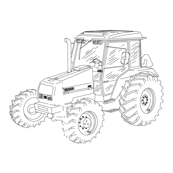
C. General description Illustrations Valtra 600---900 C 1. The models dealt with here belong to the Valtra’s small The tractor is fitted with a double clutch which acts against category tractor series. the flywheel, fully synchronized gearbox, differential lock, The tractors have 4---stroke direct injection diesel engines: hydrostatic steering, working hydraulics (alternatively Three---cylinder engine, normally aspirated;... - Page 16 69---4 Right side of tractor: 6. Starter motor 7. Fuel filling opening 1. Turbocharger (not on all models) 8. Hand priming pump, fuel system, on distributor pump 2. Thermostat housing models, on in---line pump models on the other side of 3.
- Page 17 69---5,3 Rear view of tractor: 10. Incorporating breather, hydraulic system 11. Oil filling, hydraulic system 1. Quick---release couplings, auxiliary hydraulics 12. Dipstick, hydraulic system 2. Trailer socket 13. Auxiliary hydraulic system return coupling 3. Detent for disengaging draft control (not on electro 14.
-
Page 18: C 2. Service
Traditional use of clutch pedal is, however, always possible. 65---6 Tractors 600 and 700 have engines of the 320 series and tractors 800 and 900 have engines of the 420 series. The tractors have 4---stroke direct injection diesel engines: Three---cylinder engine, normally aspirated;... -
Page 19: C 4.4. Power Shuttle
Gearbox Power shuttle C 4.2. C 4.4. A3565---18 65---8,5 The speed gearbox has four synchronized gears which The shuttle unit is synchronized and has a pressure lubri- are controlled with a speed gear lever. cation system. The forward---reverse shutle is controlled In front of the gearbox there is fitted either a power shuttle with the lever nearest to the driver. -
Page 20: C 5. Brake System
The differential of the front axle has an automatic Steering system C 6. differential brake. The differential brake engages automatically when wheel---spin occurs. Front wheel drive is engaged and disengaged by means of a control on the left side of the driver’s seat. Front wheel drive can be used in all gears, but when running on the road it should remain disengaged. -
Page 21: C 7. Hydraulic System
--- Draft control/position control combining ratio plus Hydraulic system C 7. sensitivity on the regulator, the sensitivity adjustment is automatic. --- Lowering speed (independent of load) --- Transport height --- Drive balance control system Front linkage (optional equipment) C 7.1.3. See more information in section K of the extra equipments on page 132. -
Page 22: D 1. Illustrations
D. Instruments and controls Operating instructions for the extra equipment are in section K, after each extra equipment. Illustrations D 1. NOTE: The places of the switches can vary depending on the equipment. Controls on front D 1.1. 69---9,1 For more detail see page 28. 3 Accelerator pedal 4 Brake pedals 1 Clutch pedal... -
Page 23: Instruments And Controls
Instrument panel D 1.2. .8.1 69---10,1 Front panel of instrument panel 1 2.8 Agroline ---instrument panel (alternative), LCD---dis- for more detail see play unit page 29. Continuously shows a display that cannot be chosen 1.1 Steering wheel with a switch (two functions on the bottom line): 1.2 Steering wheel adjustment 1.3 Controls for: --- Operating hours... -
Page 24: D 1.3. Controls On Right Hand Side
Controls on right hand side D 1.3. 69---11,7 Driving 1 Auxiliary hydraulic 4 for more detail see page 35 for more detail see page 39 1.1 Range gear lever 4.1 Auxiliary hydraulic valve lever 1.2 Speed gear lever Side pillar control panel 5 see point “Side pillar con- 1.3 Forward/reverse gear lever, alternative equipment on trol panel”... -
Page 25: D 1.4. Control Panel In Models With An Electrohydraulic Three
Control panel in models with an electrohydraulic three---point linkage D 1.4. 69---12,4 Rear linkage (electro hydraulically controlled hy- 2.2 Change over switch for LCD---display in Agroline---in- strument panel, if the tractor is equipped with Agro- draulic lift) 1 for more detail see page 40 line---instrument panel 1.1 Diagnose light (shows a possible fault) 2.3 Switch for front working lights, extra equipment... -
Page 26: D 1.5. Controls On Left Hand Side
Place for the fastening rack panel there are two fastening holes with M8 threads. These fastening points are located below the covering panel middle screw in the same line with the panel fixing screws and are 100 mm from each others. To make the fastening holes accessible, carefully drill 10 mm holes at exactly the above mentioned points. -
Page 27: D 1.6. Rear Side Controls
Rear side controls D 1.6. 65---13,1 For more detailed see beginning page 44. 2 Rear window intermediate position latch 1 Rear window opening device Roof console D 1.7. 69---1,5 For more detailed see beginning page 45. 4 Ventilation nozzles (extra equipment, with roof heater fan) 1 Recirculation control knob (extra equipment, with air 5 Cab light... -
Page 28: D 1.8. Driver's Seat
Driver’s seat D 1.8. 69---33 For more detailed see beginning page 46 3 Lock for turning seat 4 Seat belt anchor point 1 Adjustment forward/rearward 5 Seat back inclination 2 Suspension 6 Height adjustment, by lifting the seat 2A. Weight decal ---27--- D. -
Page 29: D 2. Instruments And Controls, More Detail
Instruments and controls, more detail D 2. Controls on frontside D 2.1. Clutch pedal (1) Accelerator pedal (3) D 2.1.1. D 2.1.3. 65---16 69---14 The engine speed can be controlled either with the foot pedal or hand throttle (on page 34). The clutch pedal is used for operating the clutch between the engine and the gearbox. -
Page 30: D 2.2. Instrument Panel
books. Fuse box, place for books (5) D 2.1.5. The fuses are rated at 5 A (6 off), 10 A (3 off), 15 A (6 off), 20 A (3 off) and 25 A (2 off), (nominal current rating). A blown fuse indicates a fault condition, which should be traced and repaired. -
Page 31: D 2.2.2. Instrument Panel
Light switch (1.4) Instrument panel (2) D 2.2.1.4. D 2.2.2. 69---21 The tractor is available with two instrument panel options. Infoline---instrument panel: --- Infoline---instrument panel is equipped with a mechanical hour meter (2.7) Agroline---instrument panel: --- Agroline---instrument panel is equipped with a digital 69---20,4 display (2.8), which has several functions. - Page 32 Coolant thermometer (2 Indicator light for main beam (2 D 2.2.2.3. D 2.2.2.5. The white zone shows the limits for the normal operating This indicator light comes on, when the main beam is on. temperature. Stop the engine if the needle moves into the red zone.
- Page 33 Displays chosen with change over switch Agroline---instrument panel (alterna- D 2.2.2.8. (2.8.1) for LCD---display in Agroline---instrument tive), LCD---display unit (2 panel (The top line has four basic functions, the bottom line one function): Functions on the top line 2.1. .8.1 69---25 The display has two lines.
- Page 34 Resetting driving trip to zero 2.3. Transmission temperature 2.1.3. .8.1 69---25,6 69---25,9 When the temperature is under 40 C the display shows ---LO--- and when over 40 C it shows the temperature. If --- Choose the driving trip on the display by pressing the the temperature rises over 90 C, clean the radiator and upper side of the change over switch for LCD---display check the gearbox oil level.
-
Page 35: Changing The Agroline Tyre/Tire Parameters For Different Tyres/Tires
Changing the Agroline tyre/tire parameters for 2.5. Side panel of instrument panel (3) D 2.2.3. different tyres/tires If the tyres/tires are changed to a different rolling diameter, Ignition switch (3 D 2.2.3.1. the instrument must be calibrated on the following way: .8.1 69---25,92 If the setting mode is not altered for over 10 seconds, the... -
Page 36: D 2.3. Controls On Right Hand Side
Controls on right hand side D 2.3. Driving (1) Speed gear lever (1 D 2.3.1.2. D 2.3.1. Range gear lever (1 D 2.3.1.1. Range gear lever on shuttle models 69---26,85 This lever (1.2) selects four synchronized speed gears, the middle position is neutral. The speed gears can be used in all three speed ranges and also in the forward 69---26,8 and reverse gears. -
Page 37: D 2.3.1.4. Hishift
Overdrive lever Operating and function of the HiShift 69---26,82 Front position, I = direct range Rear position, II = high range overdrive connected 69---26,6 Overdrive is synchronized, so it is possible to engage or disengage as the standard gears while running using the By pressing this push button (1.4) the clutch pedal is clutch pedal. - Page 38 HiShift clutch adjustment Clutch Speed > Clutch pedal up 4 km/h pedal position Clutch slides and is Speed < connecting 4 km/h Knee point Clutch pedal down Time The attached picture shows the function of the HiShift clutch and the influence of the adjustment. The curve shows the clutch pedal position according to time.
-
Page 39: Hydraulic Lift
Speed under 4 km/h, lower curve, adjusting Locking device of position control le- D 2.3.2.2. screw (1) ver (2 --- By rotating the adjusting knob (1) in the closed direction (clockwise) (the lock nut has to be slackened A), the The movable lever stop (2.2), marks the position of the clutch rises slower (the curve is gentler) and vice versa. -
Page 40: D 2.3.4. Auxiliary Hydraulic
alternatives: instructions on page 59). 1000/540 Side pillar control panel (5) D 2.3.5. --- the lever left = PTO 1000 connected --- centre position = PTO disconnected --- the lever right = PTO 540 connected 540E/540 --- the lever left = PTO 540E connected --- centre position = PTO disconnected --- the lever right = PTO 540 connected 69---28,4... -
Page 41: D 2.4. Electro
position. Openable side window (6 (on both sides) D 2.3.7. 69---28,6 Pull the handle rear side and push the window to the open Electro---hydraulic three---point linkage, control panel D 2.4. Rear linkage (electrohydraulically Position control knob (1 D 2.4.1.2. D 2.4.1. controlled lift) (1) The following controls (1---12) are only fitted on tractors with an electro---hydraulic three---point linkage. - Page 42 Lift/lower indicator lights (1 Draft control selector (1 D 2.4.1.4. D 2.4.1.7. 69---31,1 69---31,1 The lift indicator (red = lift) is lit when the lower links are This knob should be turned to the P position when the lifting, the lowering indicator (green = lowering) is lit when position control is being used (base position).
-
Page 43: D 2.4.2. Side Pillar Control Panel
Passing switch for position control Side pillar control panel (2) D 2.4.1.10. D 2.4.2. knob = forced lowering switch (1 Rear window wiper and washer (2 D 2.4.2.1. (extra equipment) 69---31,2 By pushing this switch, the lower links are lowered below the position, set by the position control knob (1.2). -
Page 44: D 2.4.3. Other Controls
Switch for rear working lights (2 Lighter (3 D 2.4.2.5. D 2.4.3.2. 69---31,6 69---31,4 Extra equipment, also for mechanical linkage model. The parking lights or full/dipped---beam headlights must be switched on when using the working lights. Switch for front PTO (3 (extra equip- D 2.4.3.3. -
Page 45: D 2.5. Controls On Left Hand Side
Controls on left hand side D 2.5. CAUTION: The brake pedals should be connected Parking brake (1) D 2.5.1. together when using parking brake. DANGER: If the tractor has the trailer brake valve, the trailer brakes also operate when using the parking brake, when the tractor engine is running (brake pedals have to be connected together). -
Page 46: D 2.7. Roof Console
Roof console D 2.7. 69---33,1 Recirculation control knob (1) Roof fan (2) D 2.7.1. D 2.7.2. (extra equipment, with air conditioning) (3---speeds, extra equipment) On the front part of the roof console there is an adjustable This fan blows air through the ventilation nozzles in the control knob for air recirculation. -
Page 47: D 2.8. Seat
69---1,4 Cab light switch (5) Sun visor (6) D 2.7.5. D 2.7.6. The cab light switch has 3 positions. The switch positions By pulling the sun visor it can be lowered and by pulling are: the string (6a) the sun visor can be raised. --- left position = light off --- centre position = door position Radio (7) - Page 48 ploughing/plowing). Lock for adjustment for D 2.8.2. forwards/rearwards (2) Lift up the lever and push the seat forwards or rearwards. Seat suspension control (3) D 2.8.3. Turn the control clockwise to make the suspension harder. The decal (3A) shows recommended settings for different driver weights.
-
Page 49: Starting And Running
E. Starting and running Before starting to drive your new tractor make yourself this manual. familiar with all instruments and controls. Study the Check all instruments immediately after starting and keep instructions given in the manual concerning the use of the checking on them while driving. -
Page 50: E 2.3. Starting Aerosol
--- Open the battery plugs to avoid risk of explosion Starting aerosol E 2.3. ---WARNING: A fully charged battery NOTE: Use of a starting aerosol is not recommended. connected directly to a dead battery can Large doses can damage the engine and the warranty cause a current surge which can cause the does not cover any damage caused in this way. -
Page 51: E 3.1.1. Forward/Reverse Models
gear 1, 2, 3 or 4. Forward/reverse models E 3.1.1. After this choose with the LH side lever the overdrive on or off. Finally, choose the desired driving direction with the RH side lever. When starting forward it can be chosen high (H) or low (L) range. -
Page 52: E 4. Stopping
Lengthwise in relation to the tractor with the front end --- 600, 700 ........ -
Page 53: Operating Instructions
F. Operating instructions Operating instructions for the extra equipment are in section K, of this book, after each extra equipment. Use of power take---off F 1. Before attaching implements to the tractor PTO unit, make Disengagement F 1.2. sure the implement is designed for 540 R.P .M PTO or 1000 R.P .M PTO. -
Page 54: F 2. Trailer
65---37 WARNING: The guard casing over the power take ---off shaft must always be fitted when the power take ---off is not being used. Trailer F 2. Gross weight of trailer = load + tare weight of trailer. Trailer socket F 2.1. -
Page 55: F 3. Three
Three---point linkage F 3. A3565---65,3 The lifting links can be attached to the lower links at one of two holes. Different holes give different lifting ranges and lifting power for the lower links. In addition, the carrier pin (1) can be fitted to the lower links at two different positions;... -
Page 56: F 3.3. Telescopic Lower Links
different lateral positions for the lower links can be implement. obtained. If the pins are fitted in the long holes, the lower When disconnecting the implement, pull the link (B) and links have a floating position in the lateral direction. turn 1/4 turn (implement lifted up). -
Page 57: F 4.1.3. Draft Control And Automatic Weight
Mechanically controlled hydraulic lift Draft control and automatic weight F 4.1.3. transmission NOTE: Draft control sensitivity can be altered by (by means of position lever) moving the attaching points of the top link (4) on the tractor. Draft control sensitivity is least when the top link is connected to the lower hole and greatest when connected to the upper hole. -
Page 58: F 4.2. Using The Electrohydraulically Controlled Hydraulic Lift
Using the electrohydraulically controlled hydraulic lift F 4.2. Lift/stop/lower switch (Autocontrol switch) F 4.2.1. 69---45 The lift/stop/lower switch (2) has 3 positions. When the corresponding position. left side is pressed down the lower links are lowered to NOTE: The implement can be lifted up by switching the the height which is set by the position control knob lift/stop/lower switch (2) to the lift position (=transport (1). -
Page 59: F 4.2.6. Draft Control
position and the lower links can then move freely up and pulling resistance increases the hydraulic lift raises the down following the movements of the implement. implement and some of the weight is transferred to the rear wheels. Thus the driving wheels maintain maximum NOTE: The control panel is fitted with lights (7) to traction. -
Page 60: F 5. Operation Of Auxiliary Hydraulics
Operation of auxiliary hydraulics F 5. Valves adjusting for single--- or F 5.1. double acting 65---49 65---50 Two auxiliary hydraulic valves are fitted as standard. Single---lever control is used for these valves. Quick action When the adjustment knob under the inner valve has been couplings are mounted at the rear of the tractor (1, as turned up the valve is double---acting, and when it is standard 4 pcs). -
Page 61: F 5.2. Action To Be Taken During Operation
CAUTION: When the auxiliary hydraulics are not in use Action to be taken during operation F 5.2. ensure the auxiliary hydraulic control lever(s) are in the central position (neutral). Overheating of the DANGER: When auxiliary cylinders and hydraulic pump may result if the levers are locked in hydraulic motors are connected ensure that the push or pull positions. -
Page 62: F 7. Use Of Top Link
Use of top link F 7. 65---54 65---51 4) Lifting height large at rear end since top link has been NOTE! When using a top link turn the bracket towards lowered on the tractor and raised on the implement. the tractor until it is fully touching the hydraulic top link. -
Page 63: Maintenance Schedule
--- Apply the parking brake to ensure the tractor cannot (excluding oil and filter costs) after 100 hours running to move. If the ground is uneven the wheels should be all new Valtra tractors. blocked. The following steps should be taken: --- Always observe the utmost cleanliness in all maintenance work. -
Page 64: G 2. Recommended Fuel And Lubricants
Biodiesel fuel --- Valtra engines are able to use esterified rape oil as biodiesel fuel --- or RME (rape oil esterified with methanol) without any technical modifications to the engine. The requirement for the acceptance is that the biodiesel that is used is very pure and that it fills the Austria ”C 1190”... -
Page 65: G 2.2. Quality Requirements Of Engine Fuel
Fuel storage --- It is also important always to use original Valtra (or Sisu G 2.2.2. Diesel) fuel filters. They guarantee sufficient filtration, --- Storing and distributing fuel must be arranged in condi- preventing impurities from damaging the fuel system. -
Page 66: G 4. Lubrication And Maintenance Schedule
Lubrication and maintenance schedule G 4. Check prefilter (on distributor pump models) and fuel The same numbering system as used on the detached maintenance schedule are placed in brackets where filter of fuel system applicable. Every 250 hours G 4.3. Daily/every 10 hours G 4.1. - Page 67 35. Adjust valves Every 500 hours G 4.4. 36. Change cab air filter and upper filter (extra equipment) See page 37. Tighten bolts and nuts of frame 16. Check brake pedal free travel 38. Grease flywheel ring gear 17. Check propulsion clutch pedal free travel When using biodiesel check and clean injectors, see the 18.
-
Page 68: Periodic Maintenance
(1) is fitted properly (800, 900), the Air filters H 1.1. models 600 and 700 have dustvalves. Cleaning: --- Always stop the engine before cleaning. A blockage of the air filter is indicated by a change of the engine beat, smoky exhaust and reduction of engine power. -
Page 69: H 2. Maintenance Daily (At Least Every 10 Hours)
Maintenance daily (at least every 10 hours) H 2. Check engine oil level (1) H 2.1. 69---59,5 69---60,2 The oil lever should come between the max. and min. marks on the dipstick (1). Adding oil should be done --- ALWAYS open the cap (3) of the expansion tank ) (2) through the oil filler cap (2). -
Page 70: H 3. Maintenance Weekly (At Least Every 50 Hours)
Lubricate the front axle and Lubricate the brake and clutch H 3.1. H 3.2. steering nipples (3) pedals (4) Use Valtra Universal Grease. 2---wheel drive models A3565---87 65---89 A. Front axle mountings: Lubricate the nipples (two) with Use Valtra Universal Grease. - Page 71 65---61 Check that the fan belt is in good condition when adjusting. A slack, worn and/or oily fan belt can cause Use Valtra Universal Grease. problems with battery charging and the cooling system. --- 1, the top link, 2 pcs Always keep a spare fan belt handy.
- Page 72 --- Check that the electrolyte level comes about 5---10 mm the tap (1) a little in the bottom of the prefilter. By opening (0.2---0.4 in) over the battery cell plates. the airscrew (2) in the upper part of the prefilter water --- Top up with distilled water if necessary.
-
Page 73: H 4. Maintenance Every 250 Hours
Maintenance every 250 hours H 4. Clean cab air filter and also upper Change engine oil and engine oil H 4.1. H 4.2. filter (extra equipment) (10) filter (11) Clean lower filter Draining H 4.2.1. 69---66,2 --- Lift up the filter housing cover (rear part first) --- Remove the filter element and knock it with the palm of the hand, use a vacuum cleaner from the direction air goes in or blow it clean with compressed air from the... - Page 74 The brake fluid level should be checked frequently. Use recommended fluid only. 65---70 Carefully clean joint before lubricating. Lubricate the joint with Valtra Grease Moly. Carry out lubrication every 250 hours or when necessary. Check tyre/tire pressures and H 4.4.
-
Page 75: H 5. Maintenance Every 500 Hours
Grease door hinges (15) H 4.6. poisonous and must be handled carefully at all times (it also corrodes the paint). There are nipples on door hinges. Use Valtra Universal Grease. Maintenance every 500 hours H 5. Check free travel of brake Check pedal free travel of H 5.1. - Page 76 Check oil level in power Check oil level in hub reduction H 5.4. H 5.6. transmission (19) gears (21) (powered front axle) 65---75 A3565---108 The oil lever should come between the max. and min. marks on the dipstick. Top up with oil when necessary. Oil Turn the wheel until the oil surface indicator line is quality should be in accordance with the table on horizontal.
-
Page 77: H 6. Maintenance Every 1000 Hours (Or Yearly)
CAUTION: If the external hydraulics are used Change pressure filter in hydraulic H 5.8. extensively and no return oil filter is used, the filter system (23) must be changed ever 250 hours. If the external hydraulics are used extensively it is recommended that a return filter should be mounted in the line (extra equipment). - Page 78 --- Subsequent to refilling, the engine should be started marks on the dipstick corresponds to 3 liters of oil. and the hydraulic lift operated for a short time, after which the level should be checked again. Replace the Change oil in differential (powered H 6.3.
- Page 79 fuel, as this could cause blockage of the fuel filter and Clean hydraulic pump suction H 6.5. impair the lubricating properties of the fuel. strainer (29) Change prefilter and fuel filter (31) H 6.7. Change prefilter (distributor models) 69---80 CAUTION: In work where the hydraulic system is subjected to abnormally heavy pollution (e.g.
- Page 80 --- Remove the safety filter Models with cyclone cleaner (600, 700) 3565---117,1 Use Valtra Universal Grease. In dusty and muddy conditions, it is necessary for 69---67,5 lubrication to be carried out much more often. When injecting new greese, ensure that enough is injected so that it pushes the dirt out of the hub.
- Page 81 Check and adjust toe---in of front Change cab air filter and upper H 6.10. H 6.12. wheels (34) filter (36) (extra equipment) Change lower filter A+ 2...6 mm 69---66,2 (4---WD:A+0...2 mm) 3565---118 Lift up the filter housing cover (rear part first) and replace the filter with a new one.
-
Page 82: H 7. Maintenance Every 2000 Hours (Or Every Other Year)
H 6.13. grease (one stroke with a grease gun) at a few points on the ring gear. With use the grease will spread round the gear. Use Valtra Moly Grease, about 1 cm Grease flywheel ring gear (38) H 6.14. - Page 83 --- 600 .........
- Page 84 --- Empty the brake fluid reservoir, open the bleed nipples. Check and clean injectors (42) H 7.4. It is better to place hoses from the nipples into a con- tainer, as the fluid corrodes the paint. Pump the brake pedal until all brake fluid in the pipes and cylinders has run out.
-
Page 85: H 8. Maintenance Every 4000 Hours
Maintenance every 4000 hours H 8. Check turbo unit (44) (not on all models) H 8.1. 69---87 Inspection and reconditioning of the turbo unit should be carried out by an authorized workshop. For trouble free functioning make sure that the air and oil filters are in good condition, that they are changed according to schedule and that the fuel system is kept clean. -
Page 86: Checks And Adjustments
I. Checks and Adjustments Check and adjustment instructions for the extra equipment are in section K, after each extra equipment. Engine I 1. Bleeding fuel system I 1.1. There should be no air in the fuel system to ensure that the motor function is of maximum efficiency. -
Page 87: I 1.2. Air Cleaner
Bleeding in---line pump system of air Air cleaner I 1.1.2. I 1.2. A3565---125,1 The bleeding of the in---line pump system differs from the bleeding of the distributor pump system as follows: 69---90 --- The fuel hand priming pump (1) is located beside the injection pump. -
Page 88: I 1.3. Maintenance
Cleaning the main filter Maintenance---cooling system I 1.3. A3565---128 Use clean and dry compressed air with a max. pressure of 500 kPa (5 bar). A3565---129 1. Direct the air flow against the inside of the filter along the folds. Do not hold the nozzle closer than 3---5 cm. The following action should be taken to make sure that 2. -
Page 89: I 2. Electrical System
Electrical system I 2. can easily be damaged if an incorrect connection is made Checking and maintenance of I 2.1. in the electrical system. For example, connection of the battery battery with wrong polarity can burn out the alternator or rectifier. -
Page 90: I 2.4. Headlight Adjustment
The fuse list when running on the public road. equipment. is on the component list of the Headlight adjustment can be carried out quickly and wiring diagram on page 108. accurately by using an optical headlight adjusting unit. If When you need a continuous electrical supply eg. to the no optical instrument is available, adjustment can be done implement, illumination etc. -
Page 91: I 4. Brake System
Adjusting: --- Turn the adjusting nut until the travel is correctly adjusted. --- Slacken the lock nut. --- Tighten the lock nut. Brake system I 4. Adjusting travel of brake pedals I 4.1. 65---93,2 The travel should be 60 mm with pedals connected ism have been changed (the parking brake is affected together. -
Page 92: I 5. Steering System
Bleed the brakes as the following (the brake pe- --- The procedure for bleeding the brake is the same on both sides. dals should not be latched together --- Check the brake fluid amount in the reservoir after --- Depress one of the brake pedals and at the same time bleeding and top up if required. -
Page 93: I 5.1.2. Adjusting Toe
Adjusting toe---in 4WD Limiting steering lock of front I 5.1.2. I 5.2. wheels (powered front axle) A3565---139 A3565---140 Slacken the locking screw (1) of the tie rod and turn the adjusting screw (2) in the desired direction. Tighten the CAUTION: When altering the track width or when locking screw. -
Page 94: I 6.1.1. 2Wd Axle
2WD axle I 6.1.1. --- Loosen and remove the bolts of the front axle (1) and tie rods (2) 50 Nm --- Pull out the axle until the desired track width is obtained. --- Move both tyres/tires the same distance. --- The front axle has three different track width possibilities. -
Page 95: I 6.2. Adjusting Track Width: Rear Axle
Adjusting track width: Rear axle I 6.2. 16.9---30, 16.9R30, 1510 2110 1610 1410 18.4R30, 480/70R30 1910 1810 2010 1710 16.9---34, 16.9R34, 18.4---34,18.4R34, 420/85R34, 460/85R34, 480/70R34, 520/70R34, 540/65R34, 13.6---38, 1710 2110 2010 1510 1610 1910 1810 1410 13.6R38, 14.9R38, 340/85R38 1610 1515 1410 2115... - Page 96 --- Carry out the general lubrication --- Bleed the fuel system if required --- Pour about 0.2 liter of motor oil into the turbocharger housing through the pressure oil pipe connection (models with turbo) --- Start the engine without racing it --- Test---run the tractor and make sure that everything works correctly.
-
Page 97: Specifications
Max permissible axle loadings (kg) J 2. Disregarding limitations due to tyre/tire equipment Tractor 600 ---2, 700 ---2/600 ---4, 700 ---4 800 ---2, 900 ---2/800 ---4, 900 ---4 On rear axle, max 40 km/h 4500/4500 4500/4500 On front axle, max 40 km/h... -
Page 98: J 3. Tyres/Tires
Tyres/tires (alternative tyre /tire equipment (pairs)) J 3. 700, Rear Front Long lower links Fixed discs 800, 900 16.9---30/8 11.2---24/8 16.9R30 12.4R24 18.4R30 13.6R24 480/70R30 360/70R24 420/85R34 340/85R24 16.9---34 13.6---24 16.9R34 13.6R24 460/85R34 380/85R24 18.4R34 14.9R24 18.4---34 14.9---24 480/70R34 380/70R24 520/70R34 420/70R24 540/65R34... -
Page 99: J 3.2. Tyre/Tire Pressures And Permissible Loadings
Tyre/tire pressures and permissible loadings (30 km/h, R tyres/tires 40 km/h) J 3.2. Pressure Max. load per Max. load per Rear wheels Front wheels Pressure (kPa) tyre/tire (kg) tyre/tire (kg) 16.9---30/8 2300 10.00---16/8 1190 16.9R30/8 2300 10.50---18/10 1605 18.4R30/8 2650 11.00---16/8 1320 1450... -
Page 100: J 5. Engine
Track widths, mm J 4. Rear wheels Track width Front wheels Track width 1410 , 1510 16.9---30, 16.9R30, 18.4R30, 1610, 1710, 1810, 10.00---16, 11.00---16/8 1410---1510---1610 480/70R30 1910, 2010, 2110 16.9---34, 16.9R34, 18.4---34, 18.4R34, 420/85R34, 460/85R34, 1410 , 1510 1320, 1415, 1520, 480/70R34, 520/70R34, 1610, 1710, 1810, 11.2---24, 12.4---24, 12.4R24... -
Page 101: J 5.1. Lubrication System (Engine)
Injection order from beginning: --- 600, 700 ........ -
Page 102: J 7. Power Transmission
Power transmission J 7. Clutch J 7.1. Construction ........double clutch Clutch operation . - Page 103 16.9- 34, 16.9R34, 18.4- 34, 18.4R34, 420/85R34, 480/70R34, 13.6- 38, 13.6R38 14.9R38 460/85R34, 520/70R34, 540/65R34, 340/85R38 230/95R48 12.2 12.1 12.4 12.7 18.1 17.9 18.4 18.8 26.4 26.2 26.9 27.4 10.8 37.4 10.7 37.2 11.0 38.2 11.3 38.9 Speed with overdrive J 7.3.2.
-
Page 104: J 7.4. Power Take
Power take---off J 7.4. 2 Nominal PTO speeds r/min ..... . . 540/1000 r/min or 540/540E (750) r/min Engine speeds in different PTO alternatives Engine speed at PTO speed PTO speeds 540E (750) - Page 105 18.4- 34, 18.4R34, 460/85R34, 520/70R34, 230/95R48 (dynamic rolling radius R = 770 r/min 540E 1000 r/min r/min 1594 1890 2074 r/min 10.3 10.6 11.6 13.2 15.6 17.2 19.3 22.8 25.1 27.3 32.4 35.6 Overdrive models 16.9 ---30, 16.9R30, 480/70R30 (dynamic rolling radius R = 695 mm) Base gear Overdrive r/min...
-
Page 106: J 7.4.2. Power Take
18.4- 34, 18.4R34, 460/85R34, 520/70R34, 230/95R48 (dynamic rolling radius R = 770 mm) Overdrive Base gear r/min r/min 540E 1000 540E 1000 r/min r/min 1594 1890 2074 1594 1890 2074 OR+L 1 OR+L 2 OR+L 3 OR+L 4 10.0 11.0 10.5 11.5 OR+H 1... -
Page 107: J 9.1. Turning Radius
Turning radius without steering brakes (front wheel 4,6/5,0 4,8/5,2 drive disengaged/ front wheel drive engaged) m Turning radius without steering brake, 2 WD models 600---700; 3.5 m, 800---900; 3.6 m. Working hydraulics J 10. Three points linkage of category II Pump type . -
Page 108: J 10.1.4. Valves For Auxiliary Hydraulics
Valves for auxiliary hydraulics J 10.1.4. As standard one 2/1---acting valve of 3---positions and one 2---acting valve of 4---positions, the float position is locked, as option two extra valves and a brake valve for trailer can be mounted. Other specifications J 11. -
Page 109: J 12. Wiring Diagram, Component List
Wiring diagram, component list (Wiring diagram on pages 110---112) J 12. Component list number 33202100 L Sym --- Code bol Component Optional or alternative equipment listed in brackets Sym --- Code G1 Battery bol Component G2 Alternator Current screw, cabin supply H1 Indicator light, direction indicators II (A2) Radio H2 Indicator light, direction indicators I... - Page 110 Wiring diagram, component list (Wiring diagram on pages 110---112) Sym --- Code Sym --- Code bol Component bol Component S14 PTO warning light contact ACB Autocontrol power lift S15 Indicator light switch, engine oil press. S16 Switch, hazard warning flashers A1E Autocontrol electronic unit 42---44 S17 Indicator light switch, diff.
-
Page 111: J 13. Wiring Diagram
Wiring diagram (component list on pages 108---109) J 13. 33202000O 69---1 69---2 J. Specifications ---110---... - Page 112 Wiring diagram (component list on pages 108---109) 69---3 69---4 ---111--- J. Specifications...
- Page 113 Wiring diagram (component list on pages 108---109) 69---5 J. Specifications ---112---...
-
Page 114: Extra Equipment
1000 kg, not together with pressure air brakes Engine K 1.1. Brake system K 1.4. Air compressor (without air conditioning), not 600 Brake valve mounting 40 l Electrical system K 1.2. Brake valve mounting 55 l Pressure air brakes (not with air conditioning, HiShift... -
Page 115: K 2. Extra Equipment, Operating And Service
Lowering links, telescopic (980 mm) + top link long Agricultural towing device (fixed) without Lower link, ball---hitch (Cat 2) (980 mm) hydraulic trailer hitch + wagon towing Short fra- Extra cylinder, power lift (600, 700) device frame Agricultural towing device (fixed) without width 295 Front linkage hydraulic trailer hitch North America + K 1.8.4. -
Page 116: K 2.1. Engine
Engine K 2.1. Electrical system K 2.2. Safety Stop Electric main circuit switch K 2.2.1. K 2.2.2. 69---98,2 69---129,1 The cut off is useful when the tractor is driving an The upper edge pressed down = electric main circuit implement (e.g. compressor, pump etc.) and there is no switch is on. -
Page 117: K 2.3. Power Transmission
Power transmission K 2.3. Front power take---off K 2.3.1. Instructions for operating 4 x 200 Nm 69---118,1 A front PTO is only available with front linkage. Maintenance When using the front PTO read the instructions for the rear General 2.1. PTO. -
Page 118: Specifications
Change when needed: --- if the opening is too small, the fastening screws of the --- Spread a little Valtra Universal Grease to the under machinery have to be loosened and the machinery surfaces of the attaching screws before fastening. -
Page 119: K 2.3.2. Hishift For The Rear Pto Switch
HiShift for the rear PTO switch K 2.3.2. Instructions for operating 69---130 The rear PTO HiShift switch (1) is situated on the right Slow engagement side panel or side pillar, depending on the equipment. --- If the load is greater, press the symbol side of the HiShift (1) down and hold until the PTO is totally connected. -
Page 120: Adjustment For The Slow Engagement
on the left side of the centre frame (= fuel tank). Adjustment for the slow engagement If the tractor is equipped with both the HiShift drive clutch and with the HiShift of the rear PTO, the highest valve pla- te (1) is for the drive clutch and the lowest (2) for the PTO switch. -
Page 121: K 2.4. Brake System
Brake system K 2.4. Trailer air pressure brakes (press air compressor) K 2.4.1. 69---99,2 The construction of the air pressure brakes 11 Two pipe system; brake line (yellow) 12 Brake pedals 1 Compressor 13 Brake fluid reservoir, common with the tractor brakes 2 Anti freeze device 14 Main brake cylinders 2A Flow control valve for anti freeze device... - Page 122 Changing and bleeding the brake fluid Grease the rubber surfaces of the trailer quick couplings (9---11) with Valtra Calsium LF--- Grease. When changing the tractor brake fluid, to empty the pipes, open the bleed nipples (7A) of the control valve (7), both Check the integrity of the system.
-
Page 123: K 2.4.2. Brake Valve Of The Trailer
Brake valve of the trailer K 2.4.2. 69---125,1 The construction of the trailer brake valve: 10 Auxiliary hydraulic valves + power lift 11 Priority valve, only in 55 l/min models 1 Brake pedals The trailer brake valve system makes use of the pressure 2 Brake fluid reservoir, common with the tractor brakes of the tractors hydraulic system (pressure ratio1:7,11 ad- 3 Main brake cylinders... -
Page 124: K 2.5. Steering System
The trailer brakes do not operate, if only one of the ke valves are situated lower down than the brake cylinder brake pedals is pressed. When the locking of the bra- of the tractor.Therefore they have to be bled before blee- ke pedals is disconnected, the tractor brakes can be ding the brake cylinder. -
Page 125: K 2.6. Frame And Wheel
Frame and wheel K 2.6. Cab and shields K 2.7. Air suspension---driver’s seat K 2.7.1. 69---101,1 CAUTION: Do not attempt to adjust the seat while than the lock limits, the seat can touch the cab side driving increased risk of an accident. trim when turning. -
Page 126: K 2.7.2. Air Conditioning
mentary and the excess pressure is released. The seat Seat belt anchor point (6) 1.6. then lowers. The anchor points for the seat belt are located on the seat. The suspension setting is set even if the tractor is Seat back inclination (7) 1.7. -
Page 127: Maintenance
NOTE: The efficiency of the air conditioning can be increased by keeping the recirculation control knob (4) in position NOTE: Make sure that the compressor starts (at low temperatures the thermostat prevents the compressor from starting). To prevent locking of the compressor, use the air conditioning for a few minutes at least once a month with the engine stop control in the off position. -
Page 128: K 2.8. Hydraulic And Towing Device
The fluid inside is almost transparent. A few Bubbles flow continuously, and when the bubbles may appear as the engine speeds up refrigerant is almost exhausted a ”mist” like flow and down. SUFFICIENT REFRIGERANT. The will be seen, with no bubbles visible. VERY high---pressure side (2) will be hot and the LITTLE REFRIGERANT. -
Page 129: Checks And Adjustments
position (on electrohydraulic linkage use the position control knob, the transport height selector must be on max position). Check the adjustment by moving the lifting link by hand. Adjustment is correct when the link moves loosely. Adjust if necessary by turning the cotter at the upper end of the links until a suitable length is obtained. -
Page 130: K 2.8.2. Agricultural Towing Device
Specifications Agricultural towing device K 2.8.2. 69---111 The agricultural towing device is used for the towing of machines where only a small part of the weight rests on the drawbar (e.g. shredders, bailing presses, 2---axle trailer etc). There are two models of the drawbar: --- With hydraulic trailer hitch --- Fixed without hydraulic trailer hitch Both the models have almost the same properties. -
Page 131: K 2.8.3. Wagon Towing Device
Instructions for operating hitch Wagon towing device K 2.8.3. Adjusting the height of the jaw 2.1. General DANGER: According to Law the driver has to ensure that all relevant precautions are followed (lockings) etc. 69---133 69---122,3 In the picture is the wagon towing device frame with fixed Adjusting the height of the mechanical and automatic jaws hitch (Piton Fix) (1) + agricultural towing device (2). -
Page 132: Maintenance And Greasing
Connecting to the jaw 2.2. Mechanical jaw NOT LOCKED PULLING PIN LOCKED 69---123 WARNING: The drawbar pin is locked in the down position when the security knob is out. When coupling the trailer the drawbar locking pin must be secured. 69---122 69---124 For lifting up the drawbar pin pull up the ring (3) at the top... -
Page 133: Specifications
Grease regularly: Specifications 3.2. --- nipple (4), use Valtra Calsium LF --- Grease. After --- Max permissible total weight for the tractor is 55 kN greasing turn the jaw from left to right at least 90 , this (5500 kg) with all jaws... -
Page 134: Maintenance
(2). Grease the pins of the lifting cylinders and the shaft of the Ensure, that the locking pins of the fastenings pins (3) are lifting links with Valtra Universal Grease. in their places when the lifting links are mounted. Specifications When using the front linkage, read the instructions of the rear linkage. -
Page 135: Alphabetical Index
L. Alphabetical index Controls on RH side, side pillar control panel, 39, 42 Controls on right hand side, 35 Controls on right hand side shortly, 23 Conversion table for common units, 137 Action to be taken during using, 51 Coolant system, 100 Adjusting track width, 92 Coolant thermometer, 31 Agricultural towing device (optional), 129... - Page 136 Hydraulic and towing device, extra equipment, operating PTO clutch lever free travel, 89 and service, 127 Hydraulic lift (electrohydraulically controlled), using, 57 Quality requirements of engine fuel, 64 Hydraulic lift, functions, 106 Hydraulic lift, mechanically controlled, using, 55 Hydraulic lift, using, 55 Range gear lever, 35 Hydraulic lifts, presentation, 20 Rear linkage (electrohydraulically controlled lift), controls...
- Page 137 Wagon towing device, extra equipment, 130 Wiring diagram, 110 Wiring diagram, component list, 108 Working hydraulics, 106 L. Alphabetical index ---136---...
-
Page 138: Conversion Table For Common Units
Conversion table for common units Metric Weights and Measures with Customary Equivalents Length 1 millimeter ........0.03937 inch 1 centimeter . - Page 139 Travel speed 1 km/h ......... . 0.62 mph 1 mph .
- Page 140 1 gallon (U.K.) ........4.5461 liters 1 gallon (U.S.) .
- Page 141 (kPa) --- 600, 700 ........
- Page 142 Ref no 39 179 21 9 (11/2002) Printed in Finland by Kopijyvä English...
Need help?
Do you have a question about the 600 and is the answer not in the manual?
Questions and answers