Table of Contents
Advertisement
Quick Links
Advertisement
Table of Contents

Related Manuals for Locomarine Mini


Summary of Contents for Locomarine Mini
- Page 1 YACHT ROUTER Installation Manual version 2.0...
- Page 2 YACHT ROUTER Read carefully. For better understanding check video tutorials on our website. Register your product for software update notifications. Thank you.
-
Page 3: Table Of Contents
Connecting WIFI and Mobile antennas to Yacht Router ...17 13.5. Connecting power supply and inserting SIM card to Yacht Router ...19 13.6. Connecting satellite or other WAN source to Yacht Router Mini ...20 13.7. Connecting Ethernet TCP/IP equipment to Yacht Router Mini ...20 13.8. -
Page 4: Copyright Notice
The contents of this manual are well prepared by Locomarine d.o.o. While we try to improve our equipment at all times, Locomarine d.o.o. shall incur no liability based on contents, updates or modification of the contents, or the lack of contents in this manual. -
Page 5: Safety And Hazard
63 cm minimum distance has to be maintained between the antenna and the occupational user and 142 cm to general public. Under such configuration, the FCC radiation exposure limits set forth for an population/uncontrolled environment can be satisfied. List of approved antennas: Omni Directional (pole), model Locomarine WIFI 5 Omni Directional (pole), model Locomarine WIFI 6 Omni Directional (pole), model Locomarine MOB 5 ANTENNA INSTALLATION: antennas MUST NOT BE COLLOCATED within 20 cm range to each other to satisfy FCC regulations. -
Page 6: Safety Instructions
YACHT ROUTER 6. SAFETY INSTRUCTIONS ELECTRICAL SHOCK HAZARD: Do not open enclosure of the equipment if you are not qualified to do it. TURN OFF THE POWER IMMEDIATELY IF WATER LEAKS INTO THE EQUIPMENT OR AN OBJECT DROPS INTO THE EQUIPMENT: Continue operating the equipment could cause electrical shock or fire. -
Page 7: About Yacht Router Mini
7. ABOUT YACHT ROUTER MINI Yacht Router Mini is designed for installation on smaller vessels with single satellite Internet source (VSAT, Inmarsat, Iridium etc). It will provide the ability to establish two vessel WIFI/LAN networks (Client-to-Vessel) which you will be able to independently and simultaneously connect to other WIFI networks (e.g. marina WIFI Hotspots), mobile networks (4G/3G/2G) or satellite Internet equipment. -
Page 8: Features
Max. data rates (Mbps): 100 1 Achieved with 9dBi outdoor antenna and VIP mobile provider. As actual range depends on many factors Locomarine d.o.o. DO NOT guarantee specified range of connectivity. 2 Achieved with 9dBi outdoor antenna. As actual range depends on many factors Locomarine d.o.o. DO NOT guarantee specified range of connectivity. -
Page 9: Client-To-Vessel Wifi
YACHT ROUTER 10.6. Power, environment and dimensions Max. transmit power (dBm): 32 Max. transmit power (mW): 1600 DC power supply input range (V): 10-30 Sensitivity of included antenna (dB): 6 AC power supply input range (V): not available Antenna connector type (on device): N-type female Automatic switching AC-DC power controller: not available Dimension (mm, WxDxH, without antenna): 45 x 45 x 180 Regulated DC power outputs: not available... -
Page 10: What Is In The Package
- Locomarine WIFI 6 antenna (WIFI, outdoor), WLAN-A-06, 1 pcs - Antenna mount screw, AC-SM-02, 3 pcs - Locomarine WIFI 5 antenna (WIFI, swivel, indoor), WLAN-A-05, 2 pcs - Antenna fixing tie, RFT-03, 3 pcs - Locomarine MOB 5 antenna (2G/3G/4G, swivel, indoor), 4G-A-01, 1 pcs... -
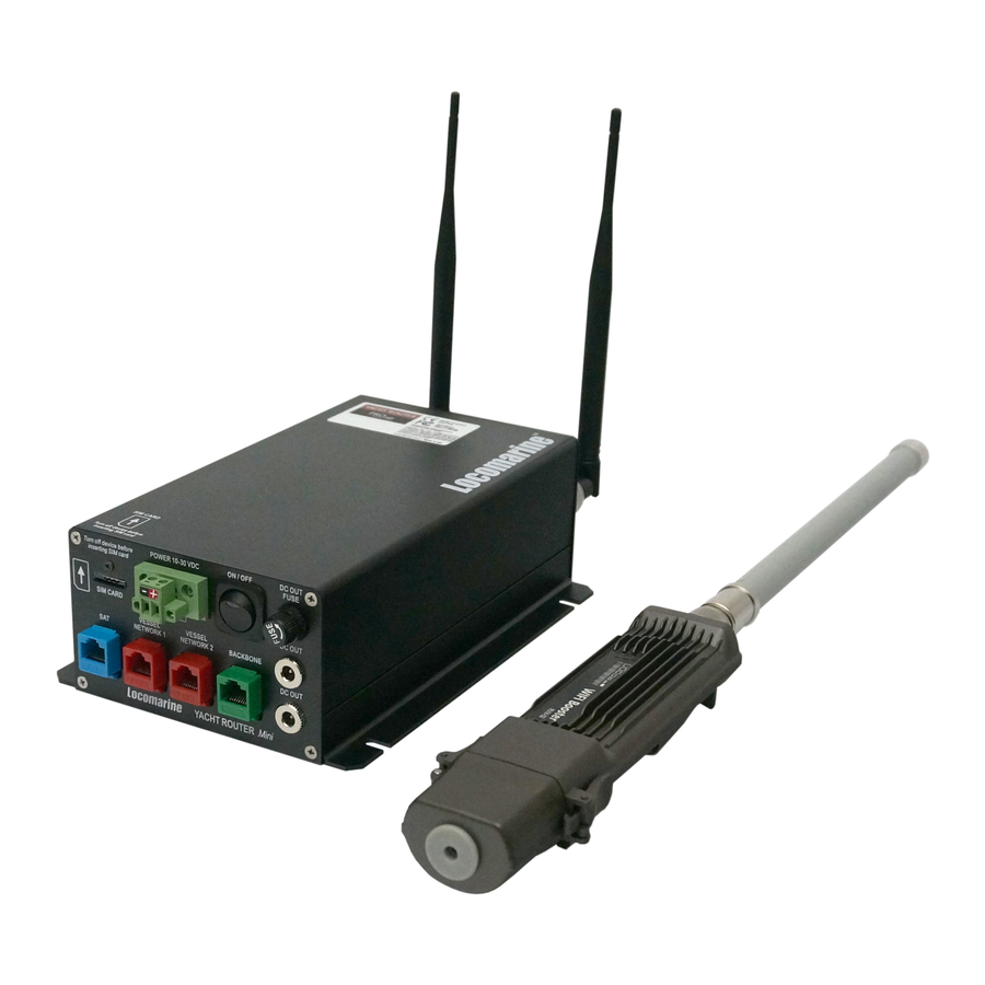
Page 11: Yacht Router Mini Introduction
YACHT ROUTER YACHT ROUTER MINI INTRODUCTION SIM card slot Fuse (1.5 A) that Mobile Vessel Networks DC power socket Power button Vessel Networks protects DC OUT WIFI antenna 1 antenna WIFI antenna 2 1 and 2. connector connector connector VESSEL NETWORK 1 and 2:... -
Page 12: Installation Instructions
YACHT ROUTER INSTALLATION INSTRUCTIONS Install Yacht Router Mini in a dry indoor space that will meet Operating environment range specifications (chapter 10.6 on page 9). Follow the installation procedure as specified in this chapter. WARNING: EXPOSURE TO RADIO FREQUENCY RADIATION! 63 CM MINIMUM DISTANCE HAS TO BE MAINTAINED BETWEEN THE SUPPLIED ANTENNA AND THE OCCUPATIONAL USER AND 142 CM TO GENERAL PUBLIC. -
Page 13: Connecting Vessel-To-Shore Wifi Booster
YACHT ROUTER 13.1. Connecting Vessel-to-Shore WIFI Booster WIFI Booster is an essential part of the Yacht Router. If WIFI Booster is not properly connected Yacht Router will not work correctly and you will receive a notification inside Control software. Yacht Router is Power-over-Ehternet device (PoE) and it uses single network cable (CAT5, CAT6 or similar) for data and power. If you are using CAT6 cable you can install WIFI Booster up to 100 meters away from the Yacht Router. - Page 14 YACHT ROUTER If you are using LAN cable with pre-terminated connectors splice one side of rubber gasket with a cutter as it is shown on the following photo. Once you slice the gasket, insert LAN cable and insert it as it is shown on the following photo.
-
Page 15: Connecting Antenna To Wifi Booster
YACHT ROUTER 13.2. Connecting antenna to WIFI Booster You can connect antenna directly to the WIFI Booster as it is shown on the following photo. You can also use antenna extension cable as it is shown on the following photo. -
Page 16: Connecting Wifi Booster To Yacht Router
YACHT ROUTER 13.3. Connecting WIFI Booster to Yacht Router To connect WIFI Booster to the Yacht Router you need to insert PoE injector (supplied within the package) as it is shown on the following photos. Plug LAN (RJ45) connector on PoE injector to any BACKBONE port on the Yacht Router. Plug DC connector on PoE injector to any DC OUT socket on the Yacht Router. -
Page 17: Connecting Wifi And Mobile Antennas To Yacht Router
YACHT ROUTER 13.4. Connecting WIFI and Mobile antennas to Yacht Router In the Yacht Router package you have received two black swivel antennas. Antenna marked with 4G is antenna for mobile networks and it must be connected to the con- nector marked as MOBILE ANTENNA. - Page 18 YACHT ROUTER Never place antennas on the same horizontal level. If you cannot avoid that position, minimum horizontal distance between antennas should be 1 meter. Use Antenna extension cables (N-type female/male) supplied with your system as it is shown on the following two photos.
-
Page 19: Connecting Power Supply And Inserting Sim Card To Yacht Router
YACHT ROUTER 13.5. Connecting power supply and inserting SIM card to Yacht Router Connect power supply cable and insert SIM card as it is shown on the following photo. IMPORTANT: Power cable consist of BLACK wire. Connect wire to BLACK positive (+) and wire to negative (ground -) power source on your vessel power supply system (battery). -
Page 20: Connecting Satellite Or Other Wan Source To Yacht Router Mini
YACHT ROUTER 13.6. Connecting satellite or other WAN source to Yacht Router Mini Yacht Router Mini is equipped with single WAN (Wide Area Network) port. It is blue RJ45 socket marked with SAT. If you want to connect your satellite communication devices like Inmarsat FleetBroadband, VSAT, Iridium or similar equipment connect it using LAN cable to this port. -
Page 21: Properly Connected Yacht Router Mini System
YACHT ROUTER 13.8. Properly connected Yacht Router Mini system Properly connected system should look like the one on the following photo. Once Yacht Router is properly connected you should proceed with software installation as it is described in User Manual which is delivered on same USB stick with Installation Manual. -
Page 22: Network Details
YACHT ROUTER NETWORK DETAILS Yacht Router Mini has reserved IP ranges that cannot be used by other connected equipment: Support network: 10.10.10.0/24 Reserved range: 10.80.0.0/12 Yacht Router Mini IP reservation details: Backbone Network: 10.80.0.0/16 Vessel Network 1: Gateway: 10.81.0.1 Free static range: 10.81.0.20 - 10.81.0.99 DHCP: 10.81.0.100 - 10.81.255.254... -
Page 23: How To Reconfigure Vessel Network Ports
HOW TO RECONFIGURE VESSEL NETWORK PORTS Each VESSEL NETWORK LAN port on Yacht Router can be reconfigured to become part of Vessel Network of your choice. For example, on Yacht Router Mini you might need more than one BACKBONE port. It is possible to reconfigure VESSEL NETWORK 1 or VESSEL NETWORK 2 to become BACKBONE port. Only BACKBONE and SAT ports cannot be reconfigured. If you need port reconfiguration please contact Locomarine Support or your local dealer. -
Page 24: Industry Canada Notice To Users
63 cm minimum distance has to be maintained between the antenna and the occupational user and 142 cm to general public. Under such configuration, the FCC radiation exposure limits set forth for a population/uncontrolled environment can be satisfied. List of approved antennas: Omni Directional (pole), model Locomarine WIFI 5 Omni Directional (pole), model Locomarine WIFI 6 Omni Directional (pole), model Locomarine MOB 5 ANTENNA INSTALLATION: antennas MUST NOT BE CO-LOCATED within 20 cm range to each other to satisfy FCC regulations.
Need help?
Do you have a question about the Mini and is the answer not in the manual?
Questions and answers