Table of Contents
Advertisement
Quick Links
Advertisement
Table of Contents

Subscribe to Our Youtube Channel
Summary of Contents for Cyrus Stereo 200
-
Page 2: Table Of Contents
IMPORTANT! ReAd befORe OPeRATINg ThIs equIPMeNT! ...1 Power supply: ................2 servicing: ...................2 Product service centres: ............2 fCC NOTICe* ................3 WelCOMe TO The WORld Of CyRus! ........4 Preparations for Installation ............4 Speaker detection..............4 INsTAllATION ................5 Key to the rear panel drawing ..........5 Placement ..................5... -
Page 3: Important! Read Before Operating This Equipment
Cyrus Stereo 200 User Instructions IMPORTANT! REAd bEfORE OPERATINg ThIS EqUIPMENT! CAUTION: The exclamation mark is to draw your ATTACHMENTS: Do not use attachments not recommended attention to important instructions and safety by the product manufacturer as they may cause hazards. -
Page 4: Power Supply
User Instructions Power supply: Servicing: The mains supply requirement for your Stereo 200 is marked Do not attempt to service this product yourself as opening on a label on the rear panel. Before connecting power, check or removing covers may expose you to dangerous voltage that this voltage is the same as your mains supply. -
Page 5: Fcc Notice
Cyrus Stereo 200 User Instructions fCC NOTICE* NOTE: This equipment has been tested and found to comply with the limits for a Class B digital device, pursuant to Part 15 of the FCC rules. These limits are designed to provide reasonable protection against harmful interference in a residential installation. -
Page 6: Welcome To The World Of Cyrus
• ferrite clamp Now is a good time to register your new Cyrus product. After removing these items, please retain the packaging. Registration takes only a few minutes, brings the added Install the amplifier in a well ventilated location away from benefit of a full two year factory warranty and adds you to sources of high temperature, dust or humidity. -
Page 7: Installation
Cyrus Stereo 200 User Instructions INSTAllATION SPEAKER SPEAKER RIGHT LEFT INPUT INPUT CHAIN INPUT MC-BUS WARNING: THIS APPLIANCE TRIGGER MUST BE EARTHED INPUT ATTENTION: CET APPAREIL DOIT ÊTRE BRANCHÉ À LA TERRE MADE IN ENGLAND Key to the rear panel drawing... -
Page 8: Placement
Phono (RCA) d and balanced input connectors b/e are cannot enter. available to link the Stereo 200 to a pre-amplifier, streamer or d/A converter etc. Connecting to the AC Mains Supply... -
Page 9: Connecting Loudspeakers
+ terminals. correct. Cable termination Connecting bare wire terminations Speaker cables for use with the Stereo 200 may be terminated • Unscrew the knobs on the four speaker terminals with spade tags, 4mm plugs or bare wire ends. -
Page 10: Chain Output
In the bi-amplified system illustration below, a preamplifier is connected to two Stereo 200 amplifiers, one to drive the speaker bass (LF) units, and one to drive the treble (HF) units. Phono input connections are shown. -
Page 11: Remote Power Control (Mc-Bus Or 12V Trigger)
Once the cable is available, connect it between the 12V example system connections below). Trigger input h on the back of the Stereo 200 and a 12V With MC-BUS established you can control the power function trigger output on the home Cinema receiver or other of the system from the front panel or remote control of the component that is controlling system power. -
Page 12: Operation
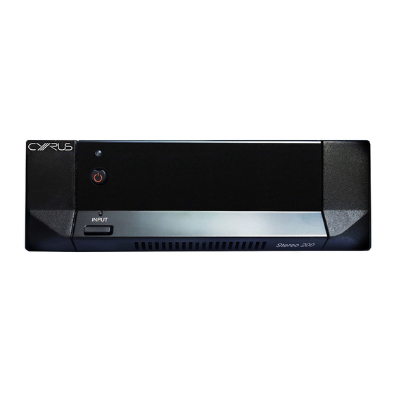
Cyrus Stereo 200 User Instructions OPERATION INPUT Stereo 200 Key to the front panel drawing Standby key Standby indicator Input indicator Input selector key... -
Page 13: Power Control
When power is first applied, the amplifier will initialise, then The INPuT Indicator c will glow red when the output of the set to Standby. Stereo 200 is muted. This occurs for a few seconds following Standby operation or if a temporary overload condition Power operation sequence arises. -
Page 14: Troubleshooting Guide
Cyrus Stereo 200 User Instructions TROUblEShOOTINg gUIdE If your Stereo 200 is not operating properly, disconnect Your amplifier has a unique fault indication system to help the power and check all connections using the notes in this you to diagnose problems. Fault condition messages will be handbook. -
Page 15: Specifications
(ref. 381mV RCA input, 775mV Balanced input.) This product should be handed over to a Cyrus reserves the right to change all specifications without notice. E & OE designated collection point to be recycled. Your cooperation in the correct disposal of this product will contribute to the effective usage of natural resources. - Page 16 Cyrus Audio Ltd., Ermine Business Park, Huntingdon, PE29 6XY, U.K.


Need help?
Do you have a question about the Stereo 200 and is the answer not in the manual?
Questions and answers