Table of Contents
Advertisement
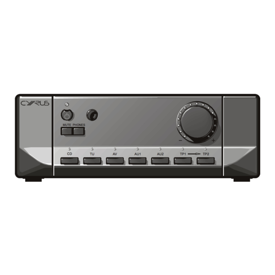
CYRUS 6 & CYRUS 8
INTEGRATED AMPLIFIER
SERVICE MANUAL
MUTE PHONES
CD
Continuous Power
Frequency Response
Damping Factor
Sensitivity
Input impedance
Output voltage
Channel Balance
Volume control accuracy
Dimensions
TU
AV
AU1
SPECIFICATIONS
Burst Power
Distortion
(50W)
S/N Ratio
(H x W x D)
Weight
Finish
AU2
TP1
TP2
70W/CH
(both driven into 8 Ohms)
110W/CH
(both driven into 4 Ohms)
340W
(IHF, one channel driven into 1 Ohm)
0.003%, 1kHz
(into 8 Ohms)
0.005%, 1kHz
(into 4 Ohms)
-3 dB, 0.2Hz and 85kHz
150
Line: 200mV
50kOhm
.
(RCA)
200mV
, 380mV
(Tape out)
101dBA
(ref. 50W)
±0.2dB
(0dB to -63dB)
±0.1dB
(0dB to -63dB)
73 x 215 x 360
, 2.8 x 8.4 x14.1
(mm)
5.5kg
Black/Silver
(Pre out)
(inches)
Jan 2006
Advertisement
Table of Contents

Related Manuals for Cyrus CYRUS 6


Summary of Contents for Cyrus CYRUS 6
-
Page 1: Service Manual
CYRUS 6 & CYRUS 8 INTEGRATED AMPLIFIER SERVICE MANUAL MUTE PHONES SPECIFICATIONS Continuous Power 70W/CH (both driven into 8 Ohms) 110W/CH (both driven into 4 Ohms) Burst Power 340W (IHF, one channel driven into 1 Ohm) Distortion 0.003%, 1kHz (into 8 Ohms) 0.005%, 1kHz... - Page 2 CYRUS 6 & 8 - Service Cautions These two symbols shown are displayed prominently on the Cyrus 8 base cover label. They indicate that the following cautions must be observed by all personnel- CAUTION: TO REDUCE THE RISK OF ELECTRICAL SHOCK, DO NOT REMOVE COVER OR BACK.
- Page 3 Cyrus 8 and Cyrus 6 variants The amplifier is available in two versions, the Cyrus 8 and the Cyrus 6. The Cyrus 8 is the higher specification unit with a larger capacity power supply (therefore increased power output) and extra features such as PSX-R connection.
- Page 4 CYRUS 6 & 8 – Block Diagram CONTROL 230VA MICRO CONTROLLER, DISPLAY AND EEPROM POWER SUPPLY 5V, +/-6VDC, +/-15V, +/-44VDC,+/- 42VDC MCBUS OVER TEMP PROTECTION UNDER VOLTAGE PROTECTION CONTROL PSU VOLTAGES CONTROL CONTROL CONTROL BI-WIRE SPEAKER DIGITALLY DIGITALLY DIGITALLY CONTROLLED...
- Page 5 The power supply for the main amplifier is 37VDC (Cyrus 6) or 43VDC (Cyrus 8), protected by fast blow fuses. In addition a regulated 34VDC (Cyrus 6) or 42VDC (Cyrus 8) is derived from a charge pump circuit and supplies the low current section of the power amplifiers.
- Page 6 CYRUS 6 & 8 Circuit Description power supply voltage supervisor for the control microprocessor. If the power supply voltage drops below 4.35V it will reset the control microprocessor. Jan 2006...
- Page 7 Pin 1 (Standby) This is an output from the Cyrus 8 to send a standby control message (logic 1, +5V) to the PSX- R, enabling the regulated power supplies of the PSX-R. Note that this pin will not change state if the Cyrus 8 detects a fault (See pin 5).
- Page 8 CYRUS 6 & 8 – Quiescent Current Quiescent current setting Switch off the power to the amplifier. Check that the amplifier is not set for PSX-R use. Connect mV meter to SK205 and no signal to input. Switch on the amplifier at the rear with nominal mains voltage: 230/115Vrms, and bring out of standby.
- Page 9 Standby. Selecting an input on the amplifier will now activate both the Cyrus 8 and the selected device (tuner or CD as connected). When the Cyrus 8 is set to Standby, all other components connected to the MCBus loop will also set to Standby.
- Page 10 CYRUS 6 & 8 – Replacing SMT Components Handling SMD resistors and capacitors are widely used in the Cyrus range of products. When handling SMD components, certain precautions should be observed- Handling SMD resistors and capacitors Always store SMD components in their original packaging or in a cool dry environment.
- Page 11 CYRUS 6 & 8 – Replacing SMT Components Keep the soldering temperature as low as possible. 260ºC is recommended for SMD rework. Most SMD components will withstand 260ºC for 5 to 10 seconds Use tin/lead/silver solder which has a lower melting point (about 179ºC). Tin/lead/silver solder paste or small gauge solder (26SWG) is recommended.
- Page 12 CYRUS 6 & 8 – Front Panel Parts Drawing de fg MUTE PHONES Front Panel parts Part Number Description AM-POWCP/ Standby knob trim AM-PLENS/ Power lens AM-LEMSM/02 Remote eye lens AM-FACIA/C6B Cyrus 6 front facia black AM-FACIA/C6S Cyrus 6 front facia silver...
- Page 13 CYRUS 6 & 8 – PCB parts list CYRUS 6 & 8 COMPONENT LIST RESISTORS R100 SMD 0805 NOT FITTED R101 SMD 0805 NOT FITTED R109 SMD 0805 4.7K MF 1/8W 1% R110 SMD 0805 100K MF 1/8W 1% R111 SMD 0805 4.7K...
- Page 14 CYRUS 6 & 8 – PCB parts list R159 SMD 0805 100K MF 1/8W 1% R164 SMD 0805 220R MF 1/8W 1% R165 SMD 0805 220R MF 1/8W 1% R201 SMD 0805 750R MF 1/8W 1% R202 SMD 0805 220R...
- Page 15 CYRUS 6 & 8 – PCB parts list R257 SMD 0805 MF 1/8W 1% R258 SMD 0805 3.9R MF 1/8W 1% R259 SMD 0805 3.9R MF 1/8W 1% R260 SMD 0805 8.2K MF 1/8W 1% R261 SMD 0805 8.2K MF 1/8W 1%...
- Page 16 CYRUS 6 & 8 – PCB parts list R411 SMD 0805 3.3K MF 1/8W 1% R412 SMD 0805 2.7K MF 1/8W 1% R413 SMD 0805 2.7K MF 1/8W 1% R414 SMD 0805 3.3K MF 1/8W 1% R415 SMD 0805 560R...
- Page 17 CYRUS 6 & 8 – PCB parts list R520 SMD 0805 100K MF 1/8W 1% R522 SMD 0805 100K MF 1/8W 1% R523 SMD 0805 100K MF 1/8W 1% R538 SMD 0805 330R MF 1/8W 1% R545 SMD 0805 330R...
- Page 18 CYRUS 6 & 8 – PCB parts list C114 SMD0805 100pF CP 50V 10% C115 SMD0805 10nF CP 50V 10% C116 SMD0805 33pF CP 50V 10% C117 RB.2/.2 22uF EL 50V 20% C118 RB.2/.2 22uF EL 50V 20% C119 RAD0.2...
- Page 19 CYRUS 6 & 8 – PCB parts list C232 SMD0805 4.7nF CP 50V 10% C233 SMD0805 4.7nF CP 50V 10% C300 RB.2/.2 22uF EL 50V 20% C301 RB.2/.3 100uF EL 50V 20% C302 RB.2/.3 100uF EL 50V 20% C303 RB.2/.4...
- Page 20 CYRUS 6 & 8 – PCB parts list C504 SMD0805 100nF CP 50V 10% C505 SMD0805 22pF CP 50V 10% C506 SMD0805 22pF CP 50V 10% C507 SMD0805 100nF CP 50V 10% C508 SMD0805 100nF CP 50V 10% C509 SMD0805...
- Page 21 CYRUS 6 & 8 – PCB parts list D310 SOT23 BZX84-C33 33V ZENER D311 SOT23 BZX84-C33 33V ZENER D312 DIODE_D1F 1SR154-400 1A Rectifier Diode D313 DIODE_D1F 1SR154-400 1A Rectifier Diode D400 RS2004M Rectifier Diode D401 DIODE_D1F 1SR154-400 1A Rectifier Diode...
-
Page 22: Integrated Circuits
CYRUS 6 & 8 – PCB parts list T200 SC74 IMT1A PNP/PNP Dual Transistor T201 SC74 IMT1A PNP/PNP Dual Transistor T202 SC74 IMT1A PNP/PNP Dual Transistor T203 SC74 IMX1 NPN/NPN Dual Transistor T204 SOT23 BC850C NPN Signal Transistor T205 SOT223 PZTA42T1 NPN HV Tran. - Page 23 CYRUS 6 & 8 – PCB parts list IC502 SO14 74HC86 Quad XOR IC503 SO14 74HC14 Schmitt Hex INV. IC505 SO16 74HC4094 8 bit shift register IC506 SO16 74HC4094 8 bit shift register IC507 SO16 74HC4094 8 bit shift register...
- Page 24 CYRUS 6 & 8 – PCB parts list Jan 2006...
- Page 25 CYRUS 6 & 8 – PCB parts list OTHER PARTS Cyrus 8 F6.3A Fuse – Cyrus 6 FS401 FUSE20MM F3.15A Cyrus 8 F6.3A Fuse – Cyrus 6 FS402 FUSE20MM F3.15A IR501 IR RECEIVER RE501 ROTARY ENCODER SW501 TACT Micro Switch 4.3mm SW502 TACT Micro Switch 9.5mm...
- Page 26 CYRUS 6 & 8 – PCB parts list Jan 2006...
- Page 27 T300 T302 (* Note: diodes D306 and D307 are short-circuited by R310 and R311 in the Cyrus 6, and will not need replacing) please note This change has been implemented during production since February 2003, from the following serial numbers:...
- Page 28 SUBJECT: Premature operation of the thermal protection circuit INTRODUCTION The thermal protection circuit of the Cyrus 6 and Cyrus 8 may activate early at too low a temperature, causing the amplifier to cut out. FAULT SYMPTOMS When playing music at higher levels, the amplifier may cut out. This is most likely to happen after a period of 10 to 20 minutes, when the heatsinks have warmed up.
Need help?
Do you have a question about the CYRUS 6 and is the answer not in the manual?
Questions and answers