Advertisement
Table of Contents
INSTALLATION INSTRUCTIONS FOR HERON 2.2
The Heron 2.2 is suitable for installation in most caravans & motorhomes. Installation in Commercial and
Industrial vehicles and equipment should be referred to AIRCOMMAND AUST for assessment of
suitability. The Heron System must be installed in accordance with national wiring regulations.
The capacity of the airconditioner to adequately cool or heat a van, is dependent on:
• The size of the van or vehicle.
• The thickness and quality of thermal insulation installed in the van.
• The expected outside or ambient conditions.
The Heron 2.2 is recommended for vans up to 5.2 m overall,
but assumes that wall and ceilings are insulated with a
minimum of 25 mm of insulation, wool or foam. The Heron 2.2
may be used in vans up to 7 metre provided the insulation is a
minimum 38mm thick and all windows are double insulated.
Windows should all have shades or curtains as a minimum.
If the van is to be used mainly in extreme conditions (40°C
plus), then be conservative, i.e. ensure the best insulation is
installed, consider double glazed windows, and size the
airconditioner down to 4.8 m maximum.
DESCRIPTION OF THE HERON 2.2 SYSTEM
The HERON 2.2 is a split system, utilizing a condenser set
(referred to throughout this text as a CON/SET) and an
airhandler (referred to as an A/H).
The Con/set is designed for installation beneath a bunk, settee,
or in the bottom of a floor cupboard. Refer fig. 1 for
dimensions.
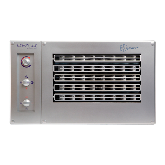
The A/H is designed for fitment into an overhead cupboard or
similar, and comes complete with facia and controls. See fig. 2.
The A/H and CON/SET are coupled by means of a pair of
refrigerant lines, and a control cable. The pipework is not
supplied with the unit, but a standard 5 m control cable is.
Before proceeding with the installation, consider a number of
important details that must be complied with in the following
description.
CHOOSING A POSITION FOR THE CON/SET
Generally, avoid installation on the left hand side (awning side), as the condenser set will discharge hot air
into this space.
Australia & UK (LHS of road) it is usual to install the con/set on the right hand side, either under a bunk,
settee or at the bottom of a floor cupboard. Conversly, continental Europe (RHS of road) the con/set should
be on the left hand side.
NOTE: Ensure that wherever the con/set is installed, reasonable access to the top of the unit is always
available, for service, and any shelving etc. above, must be easily removed. Also, the two line valves on
the back of the unit must be easily accessed.
The maximum length of pipework between the Con/set and the A/H is 5 metres. Installations exceeding this
may require extra refrigerant to be added to the system.
460
235
12
270
1
CONDENSER
440
Figure 1
AIRHANDLER A/H
220
390
FACIA
490
Figure 2
315
Advertisement
Table of Contents

Related Manuals for Aircommand HERON 2.2


Summary of Contents for Aircommand HERON 2.2
- Page 1 INSTALLATION INSTRUCTIONS FOR HERON 2.2 The Heron 2.2 is suitable for installation in most caravans & motorhomes. Installation in Commercial and Industrial vehicles and equipment should be referred to AIRCOMMAND AUST for assessment of suitability. The Heron System must be installed in accordance with national wiring regulations.
- Page 2 INSTALLING THE CONDENSER SET Marking out the floor Use the floor template as provided (or refer to fig. 3). Both, or either end of the con/set may be hard against a wall or panel, but the back of the unit must have sufficient clearance to allow easy access to the line valves (see fig.
- Page 3 PIPE INSTALLATION & CONTROL WIRING 90 mm min. The pipe work consists of a ” tube (liquid line), and a ” tube (return gas) running between the Con/set and the A/H. The ” line must be insulated with 10 x 10 mm foam rubber insulation.
- Page 4 Set up the paper template on the front panel of the cupboard, and Outline of Facia Cut out along this line accurately position it such that: A. The Facia panel will be centrally located. B. The right hand edge of the cutout is a minimum of 50 mm from right hand end of the cupboard.
-
Page 5: Power Supply
Figure I Note: The supply cord is designated Type F. If replacement is For 6.4Ø Tube, necessary it should be replaced by an Aircommand 1/3 H = 1 mm approved technician. For 9.5Ø Tube, 1/3 H = 1.5 mm... -
Page 6: Charging The System
CHARGING THE SYSTEM The system is charged with R22 in Austrualia / New Zealand or R407C in Europe, which is a prescribed refrigerant gas. Most states / countries will require the installer to have an appropriate license. The condenser set is factory precharged, but the Air handler and connecting pipework needs to be purged or evacuated of noncondensibles. - Page 7 INSTALL BITUMINOUS TAPE AROUND 9.5 FLARE NUT AT THE A/H. From the Installation kit provided, take the length of bituminous tape and wrap it around the flare nut and joining the foam rubber insulation already on the pipe. The purpose of this is to avoid formation of condensate, which may drip into the cupboard.
-
Page 8: Unit Specifications
OPERATING INSTRUCTIONS This appliance is not intended for use by young children or infirm persons without supervision. Young children should be supervised to ensure that they do not play with this appliance. This airconditioner may be used in cooling mode with outside temperatures from 18ºC to 48ºC, and inside temperatures from 18ºC to 30ºC. -
Page 10: Troubleshooting
TROUBLE SHOOTING Symptom Probable Cause Remedy Condenser set is noisy and Check that general pipework is Gently bend or pull away from vibrates not touching cabinet, lid, or panel etc chassis “Tipping” noise from Con/set Fan rotor touching inlet ring Ease motor retaining screws, and adjust “Tipping”...
Need help?
Do you have a question about the HERON 2.2 and is the answer not in the manual?
Questions and answers