Table of Contents
Advertisement
Copyright
This publication, including all photographs, illustrations and software, is protected
under international copyright laws, with all rights reserved. Neither this manual, nor
any of the material contained herein, may be reproduced without written consent of
the author.
Version 2.0e
Disclaimer
The information in this document is subject to change without notice. The manufac-
turer makes no representations or warranties with respect to the contents hereof
and specifically disclaims any implied warranties of merchantability or fitness for
any particular purpose. The manufacturer reserves the right to revise this publica-
tion and to make changes from time to time in the content hereof without obligation
of the manufacturer to notify any person of such revision or changes.
Trademark Recognition
Microsoft, MS-DOS and Windows are registered trademarks of Microsoft Corp.
MMX, Pentium, Pentium-II, Pentium-III, Celeron are registered trademarks of Intel
Corporation.
Other product names used in this manual are the properties of their respective owners
and are acknowledged.
Federal Communications Commission (FCC)
This equipment has been tested and found to comply with the limits for a Class B
digital device, pursuant to Part 15 of the FCC Rules. These limits are designed to
provide reasonable protection against harmful interference in a residential instal-
lation. This equipment generates, uses, and can radiate radio frequency energy and,
if not installed and used in accordance with the instructions, may cause harmful
interference to radio communications. However, there is no guarantee that interfer-
ence will not occur in a particular installation. If this equipment does cause harmful
interference to radio or television reception, which can be determined by turning
the equipment off and on, the user is encouraged to try to correct the interference by
one or more of the following measures:
Reorient or relocate the receiving antenna
•
Increase the separation between the equipment and the receiver
•
•
Connect the equipment onto an outlet on a circuit different from that to
which the receiver is connected
•
Consult the dealer or an experienced radio/TV technician for help
Shielded interconnect cables and a shielded AC power cable must be employed with
this equipment to ensure compliance with the pertinent RF emission limits govern-
ing this device. Changes or modifications not expressly approved by the system's
manufacturer could void the user's authority to operate the equipment.
B75H2-M3 USER MANUAL
Preface
Advertisement
Table of Contents

Related Manuals for ECS B75H2-M3


Summary of Contents for ECS B75H2-M3
- Page 1 Preface Copyright This publication, including all photographs, illustrations and software, is protected under international copyright laws, with all rights reserved. Neither this manual, nor any of the material contained herein, may be reproduced without written consent of the author. Version 2.0e Disclaimer The information in this document is subject to change without notice.
-
Page 2: Declaration Of Conformity
Declaration of Conformity This device complies with part 15 of the FCC rules. Operation is subject to the follow- ing conditions: • This device may not cause harmful interference. • This device must accept any interference received, including interference that may cause undesired operation. This device is in conformity with the following EC/EMC directives: Limits and methods of mesurement of radio disturbance char- EN 55022... -
Page 3: Table Of Contents
TABLE OF CONTENTS Preface Chapter 1 Introducing the Motherboard Introduction...................1 Pakage Contents..................1 Specifications..................2 Motherboard Components..............4 I/O Ports....................6 Chapter 2 Installing the Motherboard Safety Precautions................7 Installing the Motherboard in a Chassis........7 Checking Jumper Settings..............8 Installing Hardware................9 Installing the Processor............9 Installing the CPU Cooler............11 Installing Memory Modules...........12 Installing Add-on Cards............13 Connecting Optional Devices..........15... - Page 4 Chapter 4 Using the Motherboard Software Auto-installing under Windows XP/7/8........61 Running Setup...............61 Manual Installation................63 ECS Utility Software (Intelligent EZ Utility)........63 Chapter 5 Trouble Shooting Start up problems during assembly..........65 Start up problems after prolong use..........66 Maintenance and care tips..............66 Basic Troubleshooting Flowchart.............67...
-
Page 5: Introducing The Motherboard
Chapter 1 Introducing the Motherboard Introduction Thank you for choosing the B75H2-M3 motherboard. This motherboard is a high performance, enhanced function motherboard designed to support the LGA1155 ® ® ® ® ® socket for 2 Generation Intel Sandy/Ivy Bridge Processors. ®... -
Page 6: Specifications
Generation Intel Sandy/Ivy Bridge Processors ® • Supports New 22nm Intel Core micro-architecture • DMI 5.0GT/s Note: Please go to ECS website for the latest CPU support list. ® Chipset • Intel B75 Chipset Memory • Dual-channel DDR3 memory architecture •... - Page 7 1 x Parallel port header(LPT) System BIOS • AMI BIOS with 64Mb SPI Flash ROM - Supports ECS MIB III Utility - Supports Plug and Play, STR(S3)/STD(S4), Multi Boot - Supports Hardware Monitor - Supports ACPI 3.0 version & DMI...
-
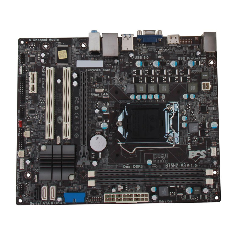
Page 8: Motherboard Components
Motherboard Components B75H2-M3 USER MANUAL... - Page 9 Table of Motherboard Components LABEL COMPONENTS 1. CPU Socket LGA1155 socket 2. CPU_FAN 4-pin CPU cooling fan connector 3. PWR_FAN 3-pin power cooling fan connector 4. DDR3_1~2 240-pin DDR3 Module slots 5. ATX_POWER Standard 24-pin ATX power connector 6. USB3F Front panel USB 3.0 header 7.
-
Page 10: I/O Ports
I/O Ports 1. PS/2 Mouse and PS/2 Keyboard combo connector Use this PS/2 port to connect a PS/2 mouse or a PS/2 keyboard. 2. USB 2.0 Ports Use the USB 2.0 ports to connect USB 2.0 devices. 3. HDMI Port DVI Port) You can connect the display device to the HDMI/DVI port. -
Page 11: Installing The Motherboard
Chapter 2 Installing the Motherboard 2-1. Safety Precautions Follow these safety precautions when installing the motherboard: • Wear a grounding strap attached to a grounded device to avoid damage from static electricity. • Discharge static electricity by touching the metal case of a safely grounded object before working on the motherboard. -
Page 12: Checking Jumper Settings
2-3. Checking Jumper Settings The following illustration shows the location of the motherboard jumpers. Pin 1 is labeled. To avoid the system instability after clearing CMOS, we recommend users to enter the main BIOS setting page to “Load Default Settings” and then “Save and Exit Setup”. -
Page 13: Installing Hardware
2-4. Installing Hardware 2-4-1. Installing the Processor • This motherboard has an LGA1155 socket. • When choosing a processor, consider the performance requirements of the system. Performance is based on the processor design, the clock speed and system bus frequency of the processor, and the quantity of internal cache memory and external cache memory. - Page 14 D. Rotate the load plate onto the package IHS (Intergraded Heat Spreader). Engage the load lever while pressing down lightly onto the load plate. Secure the load lever with the hook under retention tab. Then the cover will flick automatically. Please save and replace the cover onto the CPU socket if processor is re- moved.
-
Page 15: Installing The Cpu Cooler
2-4-2. Installing the CPU Cooler • Install the cooling fan in a well-lit work area so that you can clearly see the motherboard and processor socket. • Avoid using cooling fans with sharp edges in case the fan casing and the clips cause serious damage to the motherboard or its components. -
Page 16: Installing Memory Modules
2-4-3. Installing Memory Modules • This motherboard accommodates four memory modules. It can support two 240-pin DDR3 1600*/1333/1066. • Do not remove any memory module from its antistatic packaging until you are ready to install it on the motherboard. Handle the modules only by their edges. -
Page 17: Installing Add-On Cards
2-4-4. Installing Add-on Cards The slots on this motherboard are designed to hold expansion cards and connect them to the system bus. Expansion slots are a means of adding or enhancing the motherboard’s features and capabilities. With these efficient facilities, you can increase the motherboard’s capabilities by adding hardware that performs tasks that are not part of the basic system. - Page 18 Follow these instructions to install an add-on card: Remove a blanking plate from the system case corresponding to the slot you are going to use. Install the edge connector of the add-on card into the expansion slot. Ensure that the edge connector is correctly seated in the slot. Secure the metal bracket of the card to the system case with a screw.
-
Page 19: Connecting Optional Devices
2-4-5. Connecting Optional Devices Refer to the following for information on connecting the motherboard’s optional devices: Components Components USB3F SATA1 SATA2~4 CASE SPDIFO ME_UNLOCK F_AUDIO F_USB1~2 —— —— B75H2-M3 USER MANUAL... - Page 20 1. USB3F: Front Panel USB 3.0 header This Motherboard implements one USB 3.0 header supporting 2 extra front USB 3.0 ports, which delivers 5Gb/s transfer rate. Please make sure that the USB cable has the same pin assignment as indi- cated above.
- Page 21 4. CASE: Chassis Intrusion Detect Header This detects if the chassis cover has been removed. This function needs a chassis equipped with instrusion detection switch and needs to be enabled in BIOS. 5. ME_UNLOCK: ME Unlock Header B75H2-M3 USER MANUAL...
- Page 22 6. F_USB1~2: Front Panel USB 2.0 headers The motherboard has two USB 2.0 headers supporting four USB 2.0 ports. Addition- ally, some computer cases have USB ports at the front of the case. If you have this kind of case, use auxiliary USB connector to connect the front-mounted ports to the motherboard.
- Page 23 8. COM: Onboard serial port header Connect a serial port extension bracket to this header to add a serial port to your system. 9. LPT: Onboard parallel port Header This is a header that can be used to connect to the printer, scanner or other devices. B75H2-M3 USER MANUAL...
- Page 24 10. SPDIFO: SPDIF out header This is an optional header that provides an SPDIFO (Sony/Philips Digital Interface) output to digital multimedia device through optical fiber or coaxial connector. 11. F_AUDIO: Front Panel Audio Header The front panel audio header allows the user to install auxiliary front-oriented mi- crophone and line-out ports for easier access.
- Page 25 AC’ 97 Audio Configuration: To enable the front panel audio connector to sup- port AC97 Audio mode. If you use AC’ 97 Front Panel, please tick off the option of “ Disabled Front Panel Detect ”. If you use HD Audio Front Panel, please don’...
-
Page 26: Installing A Sata Hard Drive
2-4-6. Installing a SATA Hard Drive This section describes how to install a SATA Hard Drive. About SATA Connectors Your motherboard features four SATA connectors supporting a total of four drives. SATA refers to Serial ATA (Advanced Technology Attachment) is the standard interface for the IDE hard drives which are currently used in most PCs. -
Page 27: Connecting Case Components
2-4-7. Connecting Case Components After you have installed the motherboard into a case, you can begin connecting the motherboard components. Refer to the following: Components Components CPU_FAN SYS_FAN PWR_FAN ATX_Power ATX_12V F_PANEL 1, 2 & 5. CPU_FAN(CPU cooling FAN Power Connector), PWR_FAN(Power Cool- ing FAN Power Connector)&... - Page 28 3 & 7. ATX_POWER (ATX 24-pin Power Connector) & ATX12V (ATX 12V Power Connector) Connect the standard power supply connector to ATX_POWER. Connect the auxiliary case power supply connector to ATX12V. Connecting 24-pin power cable The ATX 24-pin connector allows you to connect to ATX v2.x power supply. With ATX v2.x power supply, users please note that when installing 24-pin power cable, the latches of power cable and the...
-
Page 29: Front Panel Header
4. Front Panel Header The front panel header (F_PANEL) provides a standard set of switch and LED headers commonly found on ATX or Micro ATX cases. Refer to the table below for information: Hard Drive Activity LED Connecting pins 1 and 3 to a front panel mounted LED provides visual indication that data is being read from or written to the hard drive. - Page 30 6. SPK: Speaker Connect the case speaker cable to SPK. This concludes Chapter 2. The next chapter covers the BIOS. B75H2-M3 USER MANUAL...
-
Page 31: Using Bios
Chapter 3 Using BIOS About the Setup Utility The computer uses the latest “American Megatrends Inc. ” BIOS with support for Windows Plug and Play. The CMOS chip on the motherboard contains the ROM setup instructions for configuring the motherboard BIOS. The BIOS (Basic Input and Output System) Setup Utility displays the system’s con- figuration status and provides you with options to set system parameters. -
Page 32: Resetting The Default Cmos Values
Press the delete key to access BIOS Setup Utility. Above image is for reference only, for details please refer to actual image. Resetting the Default CMOS Values When powering on for the first time, the POST screen may show a “CMOS Settings Wrong”... -
Page 33: Bios Navigation Keys
In this manual, default values are enclosed in parenthesis. Submenu items are denoted by a icon. The default BIOS setting for this motherboard apply for most conditions with optimum performance. We do not suggest users change the default values in the BIOS setup and take no responsibility to any damage caused by changing the BIOS settings. -
Page 34: Main Menu
Main Menu This menu shows the information of BIOS and enables you to set the system language, date and time. Main Advanced Chipset M.I.B III Boot Security Exit Choose the system default BIOS Information language System Language English System Date Thu 05/03/2012 System Time 00:00:56... -
Page 35: Advanced Menu
Advanced Menu The Advanced menu items allow you to change the settings for the CPU and other system. Main Advanced Chipset M.I.B III Boot Security Exit LAN Configuration Parameters LAN Configuration PC Health Status Power Management Setup ACPI Settings CPU Configuration SATA Configuration USB Configuration : Select Screen... -
Page 36: Lan Configuration
LAN Configuration The item in the menu shows the LAN-related information that the BIOS automatically detects. Main Advanced Chipset M.I.B III Boot Security Exit Enabled/Disabled Onboard LAN Configuration LAN 1 Controller Onboard LAN Controller Enabled Network stack Enabled Ipv4 PXE Support Enabled : Select Screen /Click: Select Item... -
Page 37: Pc Health Status
PC Health Status On motherboards support hardware monitoring, this item lets you monitor the parameters for critical voltages, temperatures and fan speeds. Main Advanced Chipset M.I.B III Boot Security Exit PC Health Status Smart Fan Function CPU Fan Speed 2872 RPM System Fan Speed 0 RPM Power Fan Speed... - Page 38 CPU/System/Power Smart Fan Control (Enabled) This item enables you to define the CPU/System/Power by smartly adjusting the CPU/System/Power Fan. When it is set at certain temperature, the CPU/System/ Power Fan PWM value will change accordingly. Smart Fan Mode (Normal) This item allows you to select the fan mode (Normal, Quiet, Silent, or Manual) for a better operation environment.
-
Page 39: Power Management Setup
Power Management Setup This page sets up some parameters for system power management operation. Main Advanced Chipset M.I.B III Boot Security Exit About Resume by Ring Power Management Setup Resume By RING Disabled Resume By PME Disabled Resume By USB (S3) Disabled Resume By PS2 KB (S3) Disabled... -
Page 40: Acpi Configuration
ACPI Configuration The item in the menu shows the highest ACPI sleep state when the system enters suspend. Main Advanced Chipset M.I.B III Boot Security Exit ACPI Settings Select the highest ACPI sleep state the system ACPI Sleep State S3 only (Suspend to ... will enter when the SUSPEND button is pressed. -
Page 41: Cpu Configuration
CPU Configuration The item in the menu shows the CPU. Main Advanced Chipset M.I.B III Boot Security Exit CPU Configuration Enabled for windows XPand Linux (OS optimized for Intel(R) Core(TM) i3-3220 CPU @ 3.30GHz Hyper-Threading EMT64 Supported Technology) and Disabled Processor Speed 3300 MHz for other OS (OS not... - Page 42 Limit CPUID Maximum (Disabled) Use this item to enable or disable the maximum CPUID value limit. Excute Disable Bit (Enabled) This item allows the processor to classify areas in memory by where application code can execute and where it cannot. When a malicious worm attempts to insert code in the buffer, the processor disables code execution, preventing damage or worm propagation.
-
Page 43: Sata Configuration
SATA Configuration Use this item to show the mode of serial-ATA configuration options. Main Advanced Chipset M.I.B III Boot Security Exit SATA Configuration Determines how SATA controller(s) operate. SATA Mode IDE Mode SATA Port1 Not Present : Select Screen /Click: Select Item SATA Port2 Enter/Dbl Click : Select Not Present... -
Page 44: Usb Configuration
USB Configuration Use this item to show the information of USB configuration. Main Advanced Chipset M.I.B III Boot Security Exit USB Support Parameters USB Configuration All USB Devices Enabled Legacy USB Support Enabled : Select Screen /Click: Select Item Enter/Dbl Click : Select +/- : Change Opt. -
Page 45: Super Io Configuration
Super IO Configuration Use this item to show the information of Super IO configuration. Main Advanced Chipset M.I.B III Boot Security Exit Set Parameters of Serial Super IO Configuration Port 0 (COMA) Super IO Chip IT8728 Serial Port 0 Configutation Parallel Port Configutation : Select Screen /Click: Select Item... - Page 46 Parallel Port Configuration Scroll to this item and press <Enter> to view the following screen: Main Advanced Chipset M.I.B III Boot Security Exit Enabled or Disabled Parallel Parallel Port Configuration Port (LPT/LPTE) Parallel Port Enabled Device Settings IO=378h; IRQ=5; DMA=3; Change Settings Auto : Select Screen...
-
Page 47: Trusted Computing
Trusted Computing Use this item to show the information of trusted computing configuration. Main Advanced Chipset M.I.B III Boot Security Exit Enable or Disable Bios TPM Configuration Support for security TPM Support Enabled device. O.S. will not show Security Device.TCG EFI Current TPM Status Information Protocol and INT1A No Security Device Found... - Page 48 Intel ME BIOS Extension Configuration Use this item to show the information of Intel ME BIOS Extension Configuration. Main Advanced Chipset M.I.B III Boot Security Exit Enabled/Disabled Intel(R) Intel ME BIOS Extension Configuration Disabled Active Management BIOS Hotkey Pressed Disabled Technology BIOS MEBx Selection Screen Disabled...
-
Page 49: Intel Smart Connect Technology
Intel(R) Smart Connect Technology Use this item to show the information of Intel(R) Smart Connect Technology. Main Advanced Chipset M.I.B III Boot Security Exit ISCT Configuration Enabled Enabled/Disabled ISCT Configuration ISCT Notification Control Enabled ISCT WLAN Power Control Enabled ISCT WWAN Power Control Enabled ISCT Sleep Duration Value Format Actual Time... -
Page 50: Chipset Menu
Chipset Menu The chipset menu items allow you to change the settings for the North Bridge chipset, South Bridge chipset and other system. Main Advanced Chipset M.I.B III Boot Security Exit System Agent Configuration System Agent (SA) PCH Configuration Parameters ME Configuration : Select Screen /Click: Select Item... - Page 51 PCH Configuration Scroll to this item and press <Enter> to view the following screen: Main Advanced Chipset M.I.B III Boot Security Exit PCH Configuration Select AC Power state when Power is re-applied after Restore AC Power Loss Power Off a power failure. Audio Configuration Azalia HD Audio Enabled...
- Page 52 ME Configuration Scroll to this item and press <Enter> to view the following screen: Main Advanced Chipset M.I.B III Boot Security Exit Management Engine Technology Configuration ME FW Version 8.1.0.1248 : Select Screen /Click: Select Item Enter/Dbl Click : Select +/- : Change Opt.
-
Page 53: Mb Intelligent Bios Iii) Menu
M.I.B III (MB Intelligent BIOS III) Menu This page enables you to set the clock speed and system bus for your system. The clock speed and system bus are determined by the kind of processor you have installed in your system. Main Advanced Chipset... - Page 54 Enhanced Intel SpeedStep Technology (Enabled) This item allows users to enable or disable the EIST (Enhanced Intel SpeedStep Tech- nology). Runtime Turbo Enable (Disabled) This item shows if CPU support Runtime Turbo. Over Clocking Extra Vol. (1/256 V) (0) This item allows you to control Extra CPU Voltage. IA Core Current Max (1/8 Amp) (896) Use this item to control CPU Current Limit.
- Page 55 Performance Memory Profiles (Automatic) This item enables you to set the Performance Memory Profile. XMP Profile 1/2 (Supported/Not Supported) These items show the information of Performance Memory Profile. Memory Timing Configuration This item shows the information of Memory Timing. CAS Latency (tCL) (9) This item determines the operation of DDR SDRAM memory CAS (column address strobe).
- Page 56 B.O.M.P Technology (Enabled) This item allows users to enable or disable B.O.M.P technology. This function can run safe setting to setup menu when system boot fail 3 times. Intel(R) Core(TM) i3-3220 CPU @ 3.30GHz This item shows the CPU information. Processor Speed (3300 MHz) This item shows the CPU speed.
-
Page 57: Boot Menu
Boot Menu This page enables you to set the keyboard NumLock state. Main Advanced Chipset M.I.B III Boot Security Exit Boot Configuration Windows 7 or other OS: Boot policy for Legacy OS Operation System Select Windows 7 or other OS Launch PXE OpROM Disabled Windows 8: Boot policy for... - Page 58 Hard Disk Drive/ CD/DVD ROM Drive/ USB/IDE Floppy Drive/ USB CD/DVD ROM Drive/ USB HardDisk Drive/ USB Flash Drive/ NETWORK Device Drive Priorities These items enable you to specify the sequence of loading the operating system. Press <Enter> to see the submenu. CSM parameters OpROM execution, boot options filter,etc.
-
Page 59: Security Menu
Security Menu This page enables you to set setup administrator password and user password. Main Advanced Chipset M.I.B III Boot Security Exit Administrator Password Status Not Install Secure Boot mode selector. User Password Status Not Install ‘Standard’ -fixed Secure boot policy, ‘Custom’ - changeable Image Administrator Password Execution policy and Secure... - Page 60 Image Execution Policy Scroll to this item to view the following screen: Main Advanced Chipset M.I.B III Boot Security Exit Internal FV Always Execute Image Execution Policy per Option ROM Deny Execute device path on Security Removable Media Deny Execute Violation.
- Page 61 Key Management Scroll to this item to view the following screen: Main Advanced Chipset M.I.B III Boot Security Exit Default Key Provisioning Disabled Force OEM default Secure Manage All Factory Keys (PK, KEK, DB, DBX) Boot Keys if System is in Install default Secure Boot keys Setup Mode.
-
Page 62: Exit Menu
Exit Menu This page enables you to exit system setup after saving or without saving the changes. Main Advanced Chipset M.I.B III Boot Security Exit Back to EZ Mode Go back to EZ Mode. Save Changes and Exit Discard Changes and Exit Save Changes and Reset Discard Changes and Reset : Select Screen... -
Page 63: Updating The Bios
Updating the BIOS You can download and install updated BIOS for this motherboard from the manufacturer’s Website. New BIOS provides support for new peripherals, improve- ments in performance, or fixes for known bugs. Install new BIOS as follows: If your motherboard has a BIOS protection jumper, change the setting to allow BIOS flashing. - Page 64 Memo B75H2-M3 USER MANUAL...
-
Page 65: Using The Motherboard Software
Click “Setup” Click the “ Utilities” button to select and button to select and software install ECS Intelligent installation program. Utility. Running Setup Follow these instructions to install device drivers and software for the motherboard: Click Setup. The installation program begins: The following screens are examples only. - Page 66 Click Next. The following screen appears: Check the box next to the items you want to install. The default options are recommended. Click Next to run the Installation Wizard. An item installation screen appears: Follow the instructions on the screen to install the items. Drivers and software are automatically installed in sequence.
-
Page 67: Manual Installation
ECS Utility Software (Intelligent EZ Utility) ECS Intelligent EZ Utility provides friendly interfaces under Windows O.S, which makes your computing more easily and conveniently. These software(s) are subject to change at anytime without prior notice. Please refer to the support disk for available software. - Page 68 Just select the one you prefer and start to download and install the drivers. eBLU ECS eBLU utility makes BIOS update faster and easier. eBLU will list the latest BIOS with a default check-mark. Click”install” button to install. Microsoft .NET Framework 3.5 is required.
-
Page 69: Trouble Shooting
Before calling for technical support or returning for warranty, this chapter may help to address some of the common questions using some basic troubleshooting tips. You may also log onto our ECS website for more information: http:// www.ecs.com.tw/ECSWebSite/Support/Support_FAQ.aspx?MenulD=49& childid=M 49&LanlD=0 a) System does not power up and the fans are not running. -
Page 70: Start Up Problems After Prolong Use
5. Check whether there is any bulked up electrolytic capacitor or abnormal component. Please logo onto our ECS website: http://www.ecs.com.tw/ECSWebSite/Support/ Technical_Support_List.aspx?MenuID=50&LanID=0 for more information. Maintenance and care tips Your computer, like any electrical appliance, requires proper care and maintenance. - Page 72 Memo B75H2-M3 USER MANUAL...
Need help?
Do you have a question about the B75H2-M3 and is the answer not in the manual?
Questions and answers