
Related Manuals for WIA Weldmatic Fabricator P135-2


Summary of Contents for WIA Weldmatic Fabricator P135-2
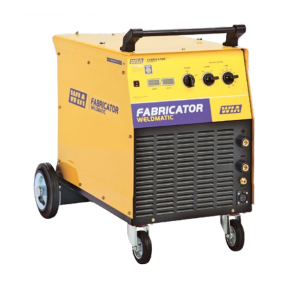
- Page 1 ® Weldmatic Fabricator [suits W64-0 wirefeeder] Operators Manual Weldmatic Fabricator MIG welder Model No. CP135-2, Iss A 02/12 CP135-40 Rev C...
- Page 2 Welding Industries of Australia An ITW Company Telephone: 1300 300 884 Facsimile: 1300 301 884 Email: Info@welding.com.au www.welding.com.au Quality Quality Reliability Reliability Performance Performance • • • •...
-
Page 3: Table Of Contents
Weldmatic Fabricator Contents Section General Information Page Safe Practices Introduction Receiving Specifications Controls Installation Normal Welding Sequence Basic Welding Information General Maintenance External Trouble Shooting Circuit Diagram Assembly and Parts Lists Warranty information Model No CP135-2, Iss A 02/12... -
Page 4: Safe Practices
Operators Manual Safe Practices When Using Read first Welding Equipment The information contained in this These notes are provided in the interests manual is set out to enable you to of improving operator safety. They should properly maintain your new equipment be considered only as a basic guide to Safe and ensure that you obtain maximum Working Habits. -
Page 5: Fire And Explosion Prevention
Weldmatic Fabricator Burn Protection coating is removed from the work surface, the area is well ventilated, or the operator The welding arc is intense and visibly bright. wears an air-supplied respirator. Its radiation can damage eyes, penetrate Work in a confined space only while it is light-weight clothing, reflect from light- being ventilated and, if necessary, while coloured surfaces, and burn the skin and... - Page 6 Operators Manual A person acting as Fire Watcher must be Shock Prevention standing by with suitable fire extinguishing Exposed conductors or other bare metal equipment during and for some time after in the welding circuit, or ungrounded welding or cutting if; electrically alive equipment can fatally shock •...
-
Page 7: Introduction
Weldmatic Fabricator 1 Introduction 2 Receiving Gas Metal Arc Welding (G.M.A.W.) is an arc Check the equipment received against the welding process where a consumable wire is shipping invoice to make sure the shipment fed by motor driven feed rolls to a welding is complete and undamaged. -
Page 8: Specifications
Operators Manual 3 Specifications Power Source Cooling Manufactured to Australian Standard Fan on demand, fan operates only as required to cool internal components. AS60974-1. Insulation Primary Voltage Class H, 140°C Rise. 415 Vac, 50 Hz Wirefeeder Circuit Breaker Rating Rated Primary Current 5 Amps 18 Amps Maximum Primary Current... -
Page 9: Controls
Weldmatic Fabricator 4 Power Source Controls Fig 1 Power Source Controls 1 On/Off Control 7 Wirefeeder Control Socket This switch provides mains power ON/OFF Connector for control cable from remote control. wirefeeder. 2 Fine Voltage Control 8 Ammeter This switch provides Fine adjustment of the This meter displays actual welding current output welding voltage over ten steps. -
Page 10: Installation
Operators Manual 5 Installation Connection to Electrical Mains Power Output Voltage Polarity Supply The design of the Weldmatic Fabricator allows selection of the output voltage polarity. NOTE. All electrical work shall only be undertaken by a qualified electrician. Positive Wire G.M.A.W. - Page 11 Weldmatic Fabricator Negative Wire Fitting Eye Bolts Some ‘self-shielded’ flux cored consumable Remove 12mm transport bolts and replace wires are operated with the work piece with supplied eye bolts and fibre washers. Positive and the consumable wire Negative. Centralise the internal nut as the eye bolt is Refer to the manufacturers data for the tightened.
-
Page 12: Normal Welding Sequence
Operators Manual 6 Normal Welding Sequence 7 Basic Welding Information Weld Start Choice of Shielding Gas Closing the welding gun switch initiates this The choice of shielding gas is largely sequence of events: determined by the consumable wire to be used. Many proprietary shielding gas •... - Page 13 Weldmatic Fabricator Establishing a Weld Setting Once the consumable wire type, wire size and shielding gas have been chosen, the two variables that are adjusted in order to obtain a the desired weld setting are; • Wirefeed speed, • Welding arc voltage. The wirefeed speed determines the welding current;...
-
Page 14: General Maintenance
Operators Manual 8 General Maintenance Gun Position Before removing the power For “down hand” fillet welding, the gun is source covers, ENSURE that the normally positioned as shown in Figure 6 equipment is disconnected from below with the nozzle end pointing in the the mains power supply. -
Page 15: External Trouble Shooting
1 Power source may have overheated. equipment should be returned to a WIA Service agent. Phone • The Weldmatic Fabricator welding 1300 300 884 for details of your power source incorporates an in- nearest service agent. - Page 16 Operators Manual Porosity in weld caused by lack of Unsatisfactory Welding Performance shielding gas and Results 1 Check that the correct gas flow rate has Erratic arc characteristics caused by been set (refer page 10) poor wirefeed 2 Check for leaks in the gas hose. Replace Erratic wirefeed is the MOST LIKELY cause if leaking of failure in all Gas Metal Arc Welding.
-
Page 17: Circuit Diagram
Weldmatic Fabricator 10 Circuit Diagrams - Power Source Fig 7 Power Source Circuit Diagram Model No CP135-2, Iss A 02/12... -
Page 18: Assembly And Parts Lists
Operators Manual 11 Assembly and Parts List - Weldmatic Fabricator Power Source 20 21 Fig 8 Weldmatic Fabricator Power Source Assembly Quality Reliability Performance • •... - Page 19 Weldmatic Fabricator Item # Part # Description WHL002 Wheel, Rubber, Castor PAN099 Base Panel AM235-0/2 Wheel, Rubber, Fixed PAN043 Front Panel PAN101 Side Panel (left) E0024 Circuit Breaker, 5 Amp PAN100 Top Panel Not shown M0019 Eye Bolt E0032 Switch, Coarse, 3 position E0033 Switch, Fine, 10 position E0031...
-
Page 20: Warranty Information
Effective 1st January 2012 • The Product not having been altered, tampered with or otherwise dealt with Welding Industries of Australia (WIA) by any person in a manner other than warrants to the original retail purchaser as intended in respect of the relevant that the Weldmatic welding machine Product;... - Page 21 Weldmatic Fabricator Notes Model No CP135-2, Iss A 02/12...
- Page 22 Operators Manual Notes Quality Reliability Performance • •...
- Page 23 Weldmatic Fabricator Notes Model No CP135-2, Iss A 02/12...
Need help?
Do you have a question about the Weldmatic Fabricator P135-2 and is the answer not in the manual?
Questions and answers