Table of Contents
Advertisement
Quick Links
Advertisement
Table of Contents

Subscribe to Our Youtube Channel
Related Manuals for Audison Prima AP5.9 bit


Summary of Contents for Audison Prima AP5.9 bit
- Page 1 AP5.9 USER’S MANUAL rev. 1.0 a...
-
Page 2: Table Of Contents
10.3 ACP6 - 6 RCA ADAPTER CABLE ..........................54 10.4 APL 2 - AP4 D / AP1 D LINK CABLE ..........................54 10.5 APK 3 - AUDISON PRIMA TOWER KIT 3 ........................55 10.6 DRC DIGITAL REMOTE CONTROL ..........................55 10.7 ECK DRC - CABLE EXTENSION KIT ..........................55 10.8 OP 1.5 TOSLINK OPTICAL CABLE 1,5 m / 59.05 in. -
Page 3: Product Description / Precautions
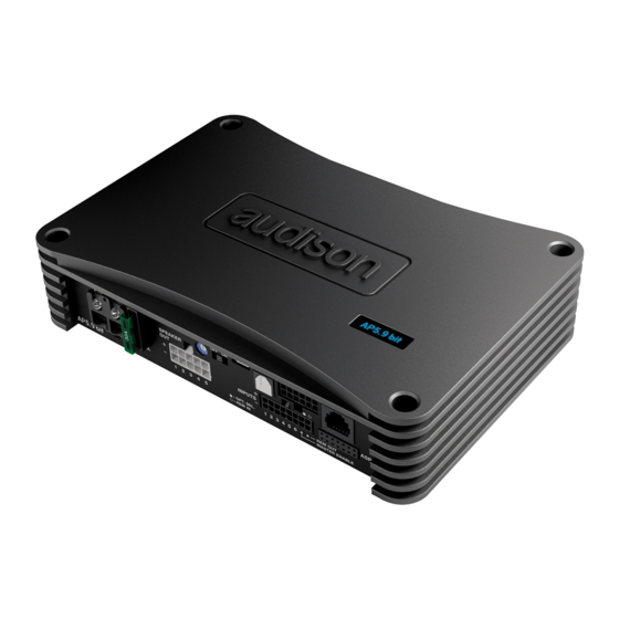
USER’S MANUAL AP5.9 bit / 1. Product descriPtion / Precautions The AP5.9 bit is a 5-channel amplifier with a 32-bit, 147-MHz digital signal processor (DSP) and 24-bit Analog-Digital and Digital-Analog converters, essential to optimize the acoustic performance of your Car Audio entertainment system. -
Page 4: Ap5.9 Bit And Drc Installation
USER’S MANUAL AP5.9 bit / 3. AP5.9 bit and drc instaLLation External Size 198 mm / 7.8 in POWER - 12V USB OPTICAL IN PRESETS UPGRADE DSP OUT OFF ON INPUTS 1 2 3 4 5 6 REM OUT MASTER ENABLE How to mount Mounting Size 178 mm / 7 in. -
Page 5: Connection Panel Description
USER’S MANUAL AP5.9 bit / 4. connection PaneLs - descriPtion POWER - 12V USB OPTICAL IN DSP OUT PRESETS UPGRADE OFF ON INPUTS 1 2 3 4 5 6 REM OUT MASTER ENABLE PoWer. + Power (11-15 VDC): connection terminal for AP5.9 bit power supply positive pole. The jack accepts a stripped cable up to 15mm/0.6"... -
Page 6: Inputs / Rem In-Out
USER’S MANUAL AP5.9 bit / inPuts / reM in-out. AP5.9 bit comes with a 16 pole multipolar connector to manage the input signals, REM IN/REM OUT connections and the control functions for the auxiliary inputs. 10 mm / 0.39 in. 200 mm / 7.87 in. -
Page 7: Asp Automatic Speaker Presence
USER’S MANUAL AP5.9 bit / asP autoMatic sPeaKer Presence Input for ASP module if using signals coming from OEM sources. This module simulates the load of the OEM factory system speakers, allowing proper interface allowing proper interfacing between the source amplified outputs and the AP5.9 bit analog inputs. -
Page 8: Optical In
The AP5.9 bit comes with a 12-pin connector to link 4 analog signals in the DSP to an Audison AP4 D amplifier or any 4-channel amplifier (see example 2). The standard product comes with a cable that can be connected to the AP4 D standard input cable by linking the relays to the inputs, respecting the colors indicated (see example 1). -
Page 9: Drc
12: blue/white MUTE N. A. 5: orange SUB + 11: orange/black SUB - 3. Audison AP5.9 bit + Audison AP4 D with connection through APL 2 AP4 D POWER - 12V USB OPTICAL IN UPGRADE DSP OUT PRESETS OFF ON... -
Page 10: Usb
USER’S MANUAL AP5.9 bit / usB. USB (micro) connection to connect the product to a PC in order to manage the functions using AP5.9 bit software. The connection is USB 1.1/2.0/3.0 compatible. uPGrade oFF-on. Switch ON allows the product to be updated in BOOT LOADER mode. (see sec. -
Page 11: Connections
USER’S MANUAL AP5.9 bit / 5. connections POWER SUPPLY AND REMOTE TURN ON HEX KEY 2,5 mm POWER - 12V USB OPTICAL IN DSP OUT PRESETS UPGRADE OFF ON 15 mm / 0.6 in. INPUTS 8 AWG Max 1 2 3 4 5 6 REM OUT MASTER ENABLE EXTERNAL AMPLIFIER... -
Page 12: Input Signals
USER’S MANUAL AP5.9 bit / INPUT SIGNALS 1. SPEAKER IN HI-LEVEL FRONT + REAR 2. SPEAKER IN HI-LEVEL FRONT WOOFER + FRONT TW + REAR POWER - 12V POWER - 12V POWER - 12V USB OPTICAL IN POWER - 12V USB OPTICAL IN DSP OUT DSP OUT... -
Page 13: Digital Optical In Input Signals
1 2 3 4 5 6 1 2 3 4 5 6 REM OUT REM OUT MASTER ENABLE MASTER ENABLE USER’S MANUAL AP5.9 bit / 7. MASTER PRE IN FRONT + REAR + AUXILIARY STEREO SOURCE 8. AUX IN L/R POWER - 12V USB OPTICAL IN PRESETS... -
Page 14: Output Signals
USER’S MANUAL AP5.9 bit / OUTPUT SIGNALS POWER - 12V USB OPTICAL IN PRESETS UPGRADE DSP OUT OFF ON INPUTS 1 2 3 4 5 6 REM OUT MASTER ENABLE White OUT 1+ 1 white out 5 + White/Black OUT 1- 7 white/black out 5 - 2 gray... -
Page 15: Preset 0: Default: 3 Way Active Front + Rear
USER’S MANUAL AP5.9 bit / 5.4.1 PRESET DEFAULT: 3 WAY ACTIVE FRONT + REAR LEFT RIGHT FRONT FRONT LEFT RIGHT FRONT FRONT sUBWOOFER POWER - 12V USB OPTICAL IN DSP OUT PRESETS UPGRADE OFF ON INPUTS 1 2 3 4 5 6 REM OUT MASTER ENABLE INPUT CONFIGURATION:... -
Page 16: Preset 1: 2 Way Active Front + 2 Passive Rear + Subwoofer
USER’S MANUAL AP5.9 bit / 5.4.2 PRESET 1: 2 WAY ACTIVE FRONT + 2 WAY PASSIVE REAR + SUBWOOFER FRONT FRONT LEFT RIGHT REAR REAR LEFT RIGHT sUBWOOFER POWER - 12V USB OPTICAL IN PRESETS UPGRADE DSP OUT OFF ON INPUTS 1 2 3 4 5 6 REM OUT... -
Page 17: Preset 2: 3 Way Active Front + Subwoofer
USER’S MANUAL AP5.9 bit / 5.4.3 PRESET 2: 3 WAY ACTIVE FRONT + SUBWOOFER LEFT RIGHT FRONT FRONT LEFT RIGHT FRONT FRONT sUBWOOFER POWER - 12V USB OPTICAL IN DSP OUT PRESETS UPGRADE OFF ON INPUTS 1 2 3 4 5 6 REM OUT MASTER ENABLE INPUT CONFIGURATION:... -
Page 18: Preset 3: Front + Rear + Subwoofer
USER’S MANUAL AP5.9 bit / 5.4.4 PRESET 3: FRONT + REAR + SUBWOOFER Mid-Hi Mid-Hi LEFT RIGHT FRONT FRONT LEFT RIGHT FRONT FRONT sUBWOOFER POWER - 12V USB OPTICAL IN PRESETS UPGRADE DSP OUT OFF ON INPUTS 1 2 3 4 5 6 REM OUT MASTER ENABLE INPUT CONFIGURATION:... -
Page 19: Preset 4: 2 Way Active Front + Rear + Subwoofer
USER’S MANUAL AP5.9 bit / 5.4.5 PRESET 4: 2 WAY ACTIVE FRONT + REAR + SUB POWER - 12V SENSITIVITY PRE IN IN A IN B SPK IN 1 2 3 4 APL 2 (optional) LEFT RIGHT FRONT FRONT LEFT RIGHT FRONT FRONT... -
Page 20: Preset 5: 3 Way Active Front + Rear + Subwoofer
USER’S MANUAL AP5.9 bit / 5.4.6 PRESET 5: 3 WAY ACTIVE FRONT + REAR + SUBWOOFER POWER - 12V SENSITIVITY PRE IN IN A IN B SPK IN 1 2 3 4 APL 2 (optional) LEFT RIGHT FRONT FRONT LEFT RIGHT FRONT FRONT... -
Page 21: Preset 6: 2 Way Active Front + Rear + Subwoofer
USER’S MANUAL AP5.9 bit / 5.4.7 PRESET 6: 2 WAY ACTIVE FRONT + REAR + SUBWOOFER POWER - 12V SENSITIVITY PRE IN IN A IN B SPK IN 1 2 3 4 APL 2 (optional) LEFT RIGHT FRONT FRONT LEFT RIGHT FRONT FRONT... -
Page 22: Preset 7: 2 Way Active Front + Rear + 2 Way Center Channel + Subwoofer
USER’S MANUAL AP5.9 bit / 5.4.8 PRESET 7: 2 WAY ACTIVE FRONT + REAR + 2 WAY CENTER CHANNEL + SUBWOOFER POWER - 12V SENSITIVITY PRE IN IN A IN B SPK IN 1 2 3 4 APL 2 (optional) CENTER CENTER LEFT... -
Page 23: Personal Computer And Digital Remote Control (Drc)
USER’S MANUAL AP5.9 bit / PERSONAL COMPUTER E DIGITAL REMOTE CONTROL (DRC) 1. Connecting AP5.9 bit to the PC DRC IN DRC/ACLink cable (provied) USB cable DRC (optional) (provided) -
Page 24: Guide For Installing/Uninstalling Prima Software And Drivers
USER’S MANUAL AP5.9 bit / 6. Guide For instaLLinG/uninstaLLinG Prima soFtWare and driVers GUIDED PROCEDURE FOR PC SOFTWARE INSTALLATION Insert the "AP5.9 bit Setup CD 1.0" in the drive on the PC you wish to use. Windows XP: access My Computer from the Windows START menu; Windows Vista: access Computer from the Windows START menu;... - Page 25 USER’S MANUAL AP5.9 bit / Windows XP: select NEXT to continue with the installation or CANCEL to interrupt it; Windows Vista: select NEXT to continue with the installation or CANCEL to interrupt it; Windows 7: select NEXT to continue with the installation or CANCEL to interrupt it; Windows 8: select NEXT to continue with the installation or CANCEL to interrupt it;...
-
Page 26: Guided Procedure For Driver Installation
USER’S MANUAL AP5.9 bit / Windows XP: follow and complete the installation procedure and click FINISH at the end of the installation; Windows Vista: follow and complete the installation procedure and click FINISH at the end of the installation; Windows 7: follow and complete the installation procedure and click FINISH at the end of the installation;... -
Page 27: Uninstalling Ap5.9 Bit Software
USER’S MANUAL AP5.9 bit / The peripheral device has been installed correctly and is ready for use. Remark: AP5.9 bit uses the HID drivers already built into Windows. For this reason, they are not included on the CD and will always install automatically. -
Page 28: How To Set Up Ap 8.9 Bit With A Pc Ap5.9 Bit With A Pc
USER’S MANUAL AP5.9 bit / 7. HoW to set uP aP 8.9 Bit WitH a Pc AP5.9 BIT WitH a Pc OFFLINE MODE OFFLINE mode can be used to analyze the software without connecting AP5.9 bit to the PC to become familiar with the numerous functions of the processor. -
Page 29: Target Mode
USER’S MANUAL AP5.9 bit / TARGET MODE In order to configure the inputs, amplified and pre-amplified power outputs, EQ and time delays for AP5.9 bit, it must be interfaced with the PC. When you get to this point you must already be aware of what type of system you intend to set up. - Page 30 USER’S MANUAL AP5.9 bit / 5. Input Configuration Any of the input channels on AP5.9 bit can be given the name corresponding to the signal coming from the source. Choose one of the following input configurations: - (1) F + R + AUX : controls Front stereo + Rear stereo + AUX input. It is possible to select from the drop-down menu which input sections to use to drive the subwoofer in the audio system.
- Page 31 (see sec. 8.1 bit Tune Advanced Manual). Head units output level instrument check The maximum output voltage and maximum undistorted level can be measured using the Audison bit Tune SOURCE CHECK tool (see sec. 7.1 bit Tune Advanced Manual)
- Page 32 USER’S MANUAL AP5.9 bit / 7. De-equalization. De-equalization of the OEM source, operation not required and not necessary if using low level inputs (Pre out). During the high level input configuration procedure, this function can be used to maximize use of the OEM head units, even if they were equalized to adapt best to the acoustics of the car they are installed in.
- Page 33 USER’S MANUAL AP5.9 bit / 9. Speaker Connection Setup. The speakers present in the system can be activated by simply clicking on them. The software assumes that if the Left tweeter, midrange or woofer are selected, the Right ones are also activated. Once the software is started, this choice will affect the crossover type and frequencies with Default settings.
- Page 34 USER’S MANUAL AP5.9 bit / 10. Output Configurations. The AP5.9 bit features 5 output channels. In this specific step of the procedure, you can assign any signal to one of the output channels, taking into account, however, the diversity of the available power outputs (see section 5.4.1) Ex.: The 2-way front can be run as:...
-
Page 35: Adjusting Acoustic Reproduction
USER’S MANUAL AP5.9 bit / ADJUSTING ACOUSTIC REPRODUCTION The following paragraphs describe the functions to adjust the system and its acoustic fine tuning. WarninG: When exploring the functions, do not change the parameters on AP5.9 bit. Take your time to get familiar with the possibilities the software offers. -
Page 36: File Main Menu
USER’S MANUAL AP5.9 bit / 7.3.2 FILE MAIN MENU By clicking on the File tab, a drop-down menu appears with the entries shown in the image: Load: it loads the entire AP5.9 bit configuration from a previously saved file (e.g.: “AP5.9 bit setup1.aps”). This function is present in both TARGET mode and in OFF LlNE mode. -
Page 37: Settings Main Menu
USER’S MANUAL AP5.9 bit / 7.3.4 SETTINGS MAIN MENU By clicking on this item, a drop-down menu appears with the entries shown in the image: I/O Configuration Wizard: Sets up the system, and puts AP5.9 bit in the conditions needed to be able to perform this operation (see sec. - Page 38 USER’S MANUAL AP5.9 bit / Options: By clicking on this item, a drop-down menu appears with the entries shown in the image: Signals: Lets you set how AP5.9 bit is turned on through: • Turn ON by SPEAKER DC (ART): When Enabled is selected, AP5.9 bit can be turned on through the amplified output (BTL) of a source connected to the inputs FL-FR-RL-RR.
- Page 39 USER’S MANUAL AP5.9 bit / Master priority: - MASTER ENABLE attenuation: sets the signal level for the master input when enabled from the terminal “MASTER ENABLE”. You can choose the activation levels between 0 dB and -18 dB - Muted Head Unit Enable: sets automatic selection of the OPTICAL/AUX inputs when the head unit connected to the MASTER input is turned off or set to MUTE (volume 0).
-
Page 40: Device Main Menu
USER’S MANUAL AP5.9 bit / 7.3.5 DEVICE MAIN MENU By clicking on this item, a drop-down menu appears with the entries shown in the image: Synchronize: This function synchronizes the PC with AP5.9 bit and vice versa due to communication losses caused by the device shutting down or for other reasons. -
Page 41: Help Main Menu
URL www.audisonbitdrive.eu will automatically start, offering the possibility to check the product manual online. 4) Diagnostic: this function is to use exclusively if requested by the Audison authorized service centre. It generates a file named “xxxxxxxxxxx.dng” that is saved on the PC desktop, to diagnose the product. -
Page 42: Select Channel
USER’S MANUAL AP5.9 bit / If you wish to check the electrical response of the Rear system together with the Subwoofer, you must clear the Front system selection. However, the software will only let you operate on a single channel and will show the message “EDIT”... - Page 43 USER’S MANUAL AP5.9 bit / In STANDARD mode: STANDARD MODE Depending on the speaker or speaker system selected during FILTER configuration, a suitable type of filter will be available. TYPE -> Full Range Low Pass High Pass Band Pass Tweeter E.g.: For the Front Woofer, only Low Pass or Band Pass will Midrange Woofer...
-
Page 44: Set Distance And Delay
USER’S MANUAL AP5.9 bit / 6. Filter slope - Hi-P Slope 12/24 dB/Oct. (Linkwitz) 6/12/18/24dB/Oct (Butterworth) - Lo-P Slope 12/24 dB/Oct. (Linkwitz) 6/12/18/24 dB/Oct (Butterworth) When starting the AP5.9 bit software, it offers Linkwitz with 12 dB/Oct. slope. E.g.: If you select Band Pass as the filter type, the same slope will be applied to both the hi-pass and low-pass as the default slope, but they can also be unbound. - Page 45 USER’S MANUAL AP5.9 bit / Preliminary remarks Fine set and Phase delay Delay assignment according to distance calculation is theoretical. Small variations must be applied due to small errors in distance measurement, back-wave reflections inside the car and, primarily, the speaker phase problem. Two speakers reproducing two frequency areas that are close to each other (e.g.: Woofer and Midrange) will simultaneously reproduce the same frequencies in their crossing area, at a attenuated level.
- Page 46 USER’S MANUAL AP5.9 bit / 5. Once the time delay settings are complete, start the musical reproduction and use the Fine Set box, moving the values up or down (except for the subwoofer since it is the farthest speaker) to fine tune the system for optimal sound.
-
Page 47: Parametric Equalizer
USER’S MANUAL AP5.9 bit / 7.3.12 PARAMETRIC EQUALIZER The AP5.9 bit software provides an equalizer, that can be managed from a maximum of 10 graphic control points which automatically place a maximum of 10 parametric equalization points. The quantity of graphic control points used doesn’t match the parametric poles quantity, which is determined by the adapting software. -
Page 48: Output Level
USER’S MANUAL AP5.9 bit / 7.3.13 OUTPUT LEVEL This section shows the settings related to the output levels of AP5.9 bit channels. The description of the points shown in the figure is given below. 1. Using one of the sliders for the output channels, you can adjust the output level (-40÷0 dB) for each channel. The sliders are enabled based on the output configuration. -
Page 49: Troubleshooting
USER’S MANUAL AP5.9 bit / 8. trouBLesHootinG SYNCHRONIZATION WITH A PC 1. AP5.9 bit operating problems If, when calibrating the system with AP5.9 bit connected to a laptop there are operating problems, try disconnecting the laptop power supply cable. With the laptop working on battery power you avoid a possible voltage difference in the USB ground between the vehicle (AP5.9 bit) and the ground (PC). -
Page 50: Firmware Upgrade
USER’S MANUAL AP5.9 bit / FIRMWARE UPGRADE If there are product UPGRADES available online, proceed as follows: - Save the previous setup (if you wish to consult it in OFFLINE mode); - Disconnect the "Speaker out" and "Sub out" AP5.9 bit on. - Set the product upgrade switch to the "ON"... - Page 51 USER’S MANUAL AP5.9 bit / 9. When successfully completed, a notification window will appear. In order to be able to use AP5.9 bit again, you must close the program on the PC and turn off AP5.9 bit. POWER - 12V PRESETS UPGRADE OPTICAL IN...
-
Page 52: Drc - Digital Remote Control (Optional)
USER’S MANUAL AP5.9 bit / 9. drc - diGitaL reMote controL (oPtionaL) The DRC is AP5.9 bit remote control system. It is a microprocessor digital system that can also remotely control and monitor any amplifiers equipped with the AC Link bus control. When first turned on, the display will show the Firmware version installed on the DRC. -
Page 53: Sel Button Functions
75 degrees Celsius. It indicates activation of the amplifier thermal protection due to overloaded outputs. It indicates activation of amplifier thermal protection due to battery voltage exceeding 16 VDC. It indicates an internal fault. You should contact an authorized Audison service centre. -
Page 54: Accessories
USER’S MANUAL AP5.9 bit / 10. accessories 10.1 ASP - AUTOMATIC SPEAKER PRESENCE ASP is indispensable when installing AP5.9 bit with some OEM sources requiring, only at the initial turn-on instant, a resistive load impedance at the outputs to detect the speakers’ presence. In case there is no load, the source disables the outputs, usually only for the Rear section. -
Page 55: Apk 3 - Audison Prima Tower Kit 3
AP5.9 bit / 10.5 APTK 3 - AUDISON PRIMA TOWER KIT 3 With the APTK 3 (Audison Prima Tower Kit 3) installation system, up to 3 AP amplifiers can be stacked in order to save space without them overheating. 10.6... -
Page 56: Op 4.5 Toslink Optical Cable 4,5 M / 177.16 In
USER’S MANUAL AP5.9 bit / 10.9 OP 4.5 TOSLINK OPTICAL CABLE 4,5 M / 177.16 IN. Optical cable with TOSLINK terminations for S/PDIF digital audio signals. Cable length 4.5 m / 177.16 in. 10.10 STA - F/F SOCKET TOSLINK ADAPTER Optical adapter to extend optical cables with TOSLINK connectors. -
Page 57: Technical Specifications
Acoustic Preset N.2 DSP Memory, DRC selectable CONTROL CONNECTIONS From / to personal computer 1 x micro USB-B To Audison Electronics DRC controls For module: Automatic Speaker Presence Optical / AUX select 12V control for Optical In / AUX enable... - Page 59 PART OF ELETTROMEDIA 62018 Potenza Picena (MC) Italy T +39 0733 870 870 - F +39 0733 870 880 www.elettromedia.it...
Need help?
Do you have a question about the Prima AP5.9 bit and is the answer not in the manual?
Questions and answers