Table of Contents
Advertisement
Quick Links
Download this manual
See also:
User Manual
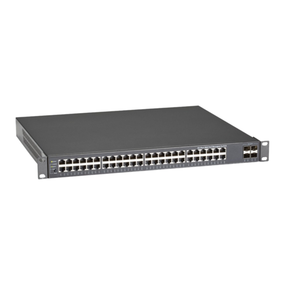
Gigabit PoE+ Ethernet Managed Switch Eco
Installation and Getting Started Guide
• LPB5028A has (20) 10/100/1000BASE-T access ports, (4) 100/1G copper/
fiber combo ports with dual-speed SFP slots, and (4) 10 Gigabit SFP+
uplink ports with dual-speed (1G/10G).
• LPB5052A has (48) 10/100/1000BASE-T access ports, and (4) 10 Gigabit
SFP+ uplink ports with dual-speed (1G/10G).
Order toll-free in the U.S.: Call 877-877-BBOX (outside U.S. call 724-746-5500)
Customer
FREE technical support 24 hours a day, 7 days a week: Call 724-746-5500 or fax 724-746-0746
Support
Mailing address: Black Box Corporation, 1000 Park Drive, Lawrence, PA 15055-1018
Information
Web site: www.blackbox.com • E-mail: info@blackbox.com
LPB5028A
LPB5052A
Advertisement
Table of Contents

Related Manuals for Black Box LPB5028A


Summary of Contents for Black Box LPB5028A
- Page 1 LPB5052A Gigabit PoE+ Ethernet Managed Switch Eco Installation and Getting Started Guide • LPB5028A has (20) 10/100/1000BASE-T access ports, (4) 100/1G copper/ fiber combo ports with dual-speed SFP slots, and (4) 10 Gigabit SFP+ uplink ports with dual-speed (1G/10G). • LPB5052A has (48) 10/100/1000BASE-T access ports, and (4) 10 Gigabit SFP+ uplink ports with dual-speed (1G/10G).
- Page 2 Disclaimer: Black Box Network Services shall not be liable for damages of any kind, including, but not limited to, punitive, consequential or cost of cover damages, resulting from any errors in the product information or specifications set forth in this document and Black Box Network Services may revise this document at any time without notice.
- Page 3 FCC and IC RFI Statements Federal Communications Commission and Industry Canada Radio Frequency Interference Statements This equipment generates, uses, and can radiate radio-frequency energy, and if not installed and used properly, that is, in strict accordance with the manufacturer’s instructions, may cause inter ference to radio communication. It has been tested and found to comply with the limits for a Class A computing device in accordance with the specifications in Subpart B of Part 15 of FCC rules, which are designed to provide reasonable protection against such interference when the equipment is operated in a commercial environment.
- Page 4 NOM Statement Instrucciones de Seguridad (Normas Oficiales Mexicanas Electrical Safety Statement) 1. Todas las instrucciones de seguridad y operación deberán ser leídas antes de que el aparato eléctrico sea operado. 2. Las instrucciones de seguridad y operación deberán ser guardadas para referencia futura. 3.
-
Page 5: About This Guide
To download the Gigabit PoE+ Ethernet Managed Switch Eco user manual from the Web site: 1. Go to www.blackbox.com 2. Enter the part number (LPB5028A or LPB5052A) in the search box: 3. Click on the “Resources” tab on the product page, and select the document you wish to download. -
Page 6: Table Of Contents
Table of Contents Contents 1. Overview ....................................8 1.1 Introduction ..................................8 1.2 Switch Architecture ................................9 1.3 Network Management Options ............................9 2. Hardware Description ................................10 2.1 1000BASE-T Ports ................................10 2.2 SFP Transceiver Slots .................................10 2.3 Port and System LEDs ..............................10 2.4 Power Supply Socket ................................11 2.5 Mode Status LEDs ................................11 3. - Page 7 Table of Contents 7.3.7 Adjusting Existing Category 5 Cabling to Run 1000BASE-T ................... 30 7.3.8 Fiber Standards ............................... 30 8. Specifications...................................31 Glossary ....................................33 724-746-5500 | blackbox.com Page 7...
-
Page 8: Overview
Two models are available: • Gigabit PoE+ Ethernet Managed Switch Eco – 24-Port (product code LPB5028A). This model has (20) 10/100/1000BASE0-T access ports, (4) copper/fiber combo ports with dual-speed SFP slots, and (4) 10 Gigabit SFP+ uplink ports with dual speed (1G/10G). -
Page 9: Switch Architecture
To download the Gigabit PoE+ Ethernet Managed Switch Eco user manual from the Web site: 1. Go to www.blackbox.com 2. Enter the part number (LPB5028A or LPB5052A) in the search box: 3. Click on the “Resources” tab on the product page, and select the document you wish to download. -
Page 10: Hardware Description
2. Hardware Description 2.1 1000BASE-T Ports The LPB5028A switch has (20) 1000BASE-T RJ-45 ports and (4) copper/fiber combo ports with dual-speed SFP slots, and the LPB5052A switch has (48) 1000BASE-T RJ-45 ports. All RJ-45 ports support automatic MDI/MDI-X operation, auto-negotiation and IEEE 802.3x auto-negotiation of flow control, so the optimum data rate and transmission can be selected automatically. -
Page 11: Power Supply Socket
Chapter 2: Hardware Description Table 2-3. System Status LED. Condition Status System LED Green, OFF Lights when power is on and the switch is ready. 2.4 Power Supply Socket The power socket uses an AC power cord and is located on the rear panel of the switch. See Figure 1-2. 2.5 Mode Status LEDs The Gigabit PoE+ Ethernet Managed Switch Eco has a mode switch. -
Page 12: Network Planning
3.2 Application Examples The Gigabit PoE+ Ethernet Managed Switch Eco LPB5028A has 24 Gigabit Ethernet twisted-pair ports with auto MDI-X and 4 slots for removable SFP modules that support LC and BiDi-LC fiberoptic modules. The LPB5052A has 48 Gigabit Ethernet twisted- pair ports with auto MDI-X and 4 SFP module slots. - Page 13 Chapter 3: Network Planning Gigabit PoE+ Ethernet Managed Switch Eco (LPB5052A) Printer AP server Figure 3-2. Peer-to-peer network connection. Gigabit PoE+ Ethernet Managed Switch Eco (LPB5052A) Internet Router 8-port switch Switch 10-port switch Sales Research and Development (R&D) Figure 3-3. Office network connection. 724-746-5500 | blackbox.com Page 13...
-
Page 14: Installing The Switch
1000BASE-T operation. Check the following criteria against the current installation of your network: • Cable type: Use unshielded twisted pair (UTP) or shielded twisted pair (STP) cable with RJ-45 connectors. Black Box recommends Category 5 or Category 5e with maximum length of 328 feet (100 meters) for 100BASE-TX, and Category 5e or 6 with maximum length of 328 feet (100 meters) for 1000BASE-T. -
Page 15: What's Included
• AC power cord • RS-232 DB9 to DB9 Console Cable To download the getting started and installation guide (this document) and the user manual from the Black Box Web site: 1. Go to www.blackbox.com 2. Enter the part number (LPB5028A or LPB5052A) in the search box: 3. -
Page 16: Desktop Or Shelf Mounting
Chapter 4: Installing the Switch Step 2. Mount the device in the rack (via the included rackmount kit), using four rackmounting screws (not provided). Be sure to secure the lower rackmounting screws first to prevent the brackets from bending from the weight of the switch. Figure 4-4. -
Page 17: Installing An Optional Sfp Transceiver
Chapter 4: Installing the Switch Step 2. Set the device on a flat surface near an AC power source, making sure there are at least two inches of space on all sides for proper air flow. Step 3. If installing a single switch only, go to Section 4.6, Connecting to a Power Source, at the end of this Chapter. Step 4. -
Page 18: Connecting To A Power Source
Chapter 4: Installing the Switch To install an SFP transceiver, follow these steps: Step 1. Consider network and cabling requirements to select an appropriate SFP transceiver type. Step 2. Insert the transceiver with the optical connector facing outward and the slot connector facing down. Note that SFP transceivers are keyed so they can only be installed in one orientation. -
Page 19: Operation Of Web-Based Management
Chapter 4: Installing the Switch Table 4-2. Serial cable wiring. Function Mnemonic Pin Carrier Receive Data Transmit Data Data Terminal Ready Signal Ground Data Set Ready Request to Send Clear to Send NOTE: No other pins are used. Figure 4-9. Plug in the console port. The Gigabit PoE+ Ethernet Managed Switch Eco’s terminal DB9 console port default values are listed below: The serial port’s configuration requirements are as follows: •... - Page 20 Chapter 4: Installing the Switch Figure 4-10. Windows security screen. NOTE: If you need to re-configure a function or parameter, refer the detail in the User Guide. Or you could access the Switch and click “help” under the web GUI and a help screen will pop-up to teach you how to set the parameters. 724-746-5500 | blackbox.com Page 20...
-
Page 21: Making Network Connections
Chapter 5: Making Network Connections 5. Making Network Connections 5.1 Connecting Network Devices You can connect the switch to 10-, 100- or 1000-Mbps network cards in PCs and servers, as well as to other switches and hubs. You can also connect the switch to remote devices using optional SFP transceivers. 5.2 Twisted-Pair Devices Each device requires an unshielded twisted-pair (UTP) cable with RJ-45 connectors at both ends. -
Page 22: Fiber Optic Sfp Devices
Chapter 5: Making Network Connections Figure 5-1. Network wiring connections. 5.3 Fiber Optic SFP Devices An optional Gigabit SFP transceiver can be used for a backbone connection between switches, or for connecting to a high-speed server. Each single-mode fiber port requires 9/125 micron single-mode fiber optic cable with an LC connector at both ends. Each multimode fiber optic port requires 50-/125- or 62.5-/125-micron multimode fiber optic cabling with an LC connector at both ends. -
Page 23: Connectivity Rules
Chapter 5: Making Network Connections Figure 5-2. Making fiber port connections. Step 4. As a connection is made, check the Link LED on the switch corresponding to the port to be sure that the connection is valid. The fiber optic ports operate at 1 Gbps. The maximum length for fiber optic cable operating at Gigabit speed will depend on the fiber type as listed under 1000 Mbps Gigabit Ethernet Collision Domain in Section 5.4. - Page 24 Chapter 5: Making Network Connections Table 5-3. Maximum 1000BASE-LX/LHX/XD/ZX Gigabit Fiber cable length. Fiber Size Fiber Bandwidth Maximum Cable Length Connector 9/125 micron single-mode fiber 1310 nm 6.2 miles (10 km) 9/125 micron single-mode fiber 1550 nm 18.64 miles (30 km) 31.06 miles (50 km) Table 5-4.
-
Page 25: Cable Labeling And Connection Records
Chapter 6: Cable Labeling and Connection Records 6. Cable Labeling and Connection Records When planning a network installation, it is essential to label the opposing ends of cables and to record where each cable is connected. This will allow users to easily locate interconnected devices, isolate faults, and change your topology easily. To best manage the physical implementations of your network, follow these guidelines: •... -
Page 26: Troubleshooting
Chapter 7: Troubleshooting 7. Troubleshooting 7.1 Basic Troubleshooting Tips Most problems are caused by the following situations. Check for these items first when starting your troubleshooting: Connecting to devices that have a fixed full duplex configuration. The RJ-45 ports are configured as “Auto,” that is, when connecting to the attached devices, the switch will operate in one of two ways to determine the link speed and the communication mode (half duplex or full duplex): •... -
Page 27: Power And Cooling Problems
Chapter 7: Troubleshooting Table 7-1. Troubleshooting chart. Symptom Action System LED is • Check connections between the switch, the power cord, and the wall outlet. • Contact your dealer for assistance. Link LED is Off • Verify that the switch and attached device are powered on.• Be sure the cable is plugged into the switch and corresponding device. -
Page 28: 10Base-T/100Base-Tx Pin Assigments
Chapter 7: Troubleshooting 7.3.2 10BASE-T/100BASE-TX Pin Assignments Use unshielded twisted-pair (UTP) or shielded twisted-pair (STP) cable for RJ-45 connections: 100-ohm Category 3 or better cable for 10 Mbps connections, or 100-ohm Category 5 or better cable for 100 Mbps connections. Also be sure that the length of any twisted-pair connection does not exceed 328 feet (100 meters). -
Page 29: Crossover Wiring
Chapter 7: Troubleshooting 7.3.4 Crossover Wiring If the twisted-pair cable is to join two ports and either both ports are labeled with an “X” (MDI-X) or neither port is labeled with an “X” (MDI), a crossover must be implemented in the wiring. (When auto-negotiation is enabled for any RJ-45 port on this switch, you can use either straight-through or crossover cable to connect to any device type.) You must connect all four wire pairs as shown in the following diagram to support Gigabit Ethernet. -
Page 30: Cable Testing For Existing Category 5 Cable
Chapter 7: Troubleshooting 7.3.6 Cable Testing for Existing Category 5 Cable Installed Category 5 cabling must pass tests for Attenuation, Near-End Crosstalk (NEXT), and Far-End Crosstalk (FEXT). This cable testing information is specified in the ANSI/TIA/EIA-TSB-67 standard. Additionally, cables must also pass test parameters for Return Loss and Equal-Level Far-End Crosstalk (ELFEXT). -
Page 31: Specifications
Buffer Architecture 4096 bytes on-chip frame buffer Network Interface Ports 1–24 (LPB5028A) or Ports 1–48 (LPB5052A): RJ-45 connector, auto MDI/X 10BASE-T: RJ-45 (100-ohm, UTP cable; Category 3 or better); 100BASE-TX: RJ-45 (100-ohm, UTP cable; Category 5 or better); 1000BASE-T: RJ-45 (100-ohm, UTP or STP cable; Category 5, 5e, or 6) *Maximum Cable Length = 328 ft (100 m) Ports 24–28 (LPB5028A) or 48–52 (LPB5052A): 1G/10G SFP ports... - Page 32 Chapter 10: Specifications Switch Features (continued) Approvals Emissions: EN55022 (CISPR 22) Class A EN 61000-3; FCC Class A; CE Mark; Immunity: EN 61000-4-2/3/4/5/6/8/11; EN 55024 Standards IEEE 802.3 => 10Base-T Ethernet (Twisted-pair Copper); IEEE 802.3u => 100Base-TX Ethernet (Twisted-pair Copper); IEEE 802.3ab =>...
-
Page 33: Glossary
Glossary Glossary 10BASE-T: IEEE 802.3 specification for 10 Mbps Ethernet over two pairs of Category 3, 4, or 5 UTP cable. 100BASE-TX: IEEE 802.3u specification for 100 Mbps Ethernet over two pairs of Category 5 UTP cable. 1000BASE-LH: Specification for long-haul Gigabit Ethernet over two strands of 9/125 micron core fiber cable. 1000BASE-LX IEEE 802.3z: Specification for Gigabit Ethernet over two strands of 50/125, 62.5/125 or 9/125 micron core fiber cable. - Page 34 Glossary Media Access Control (MAC): A portion of the networking protocol that governs access to the transmission medium, facilitating the exchange of data between network nodes. MIB: An acronym for Management Information Base. It is a set of database objects that contains information about the device. Modal Bandwidth: Bandwidth for multimode fiber is referred to as modal bandwidth because it varies with the modal field (or core diameter) of the fiber.
- Page 35 NOTES 724-746-5500 | blackbox.com Page 35...
- Page 36 About Black Box Black Box provides an extensive range of networking and infrastructure products. You’ll find everything from cabinets and racks and power and surge protection products to media converters and Ethernet switches all supported by free, live 24/7 Tech support available in 60 seconds or less.
Need help?
Do you have a question about the LPB5028A and is the answer not in the manual?
Questions and answers