Table of Contents
Advertisement
User Manual
Installation and Operation
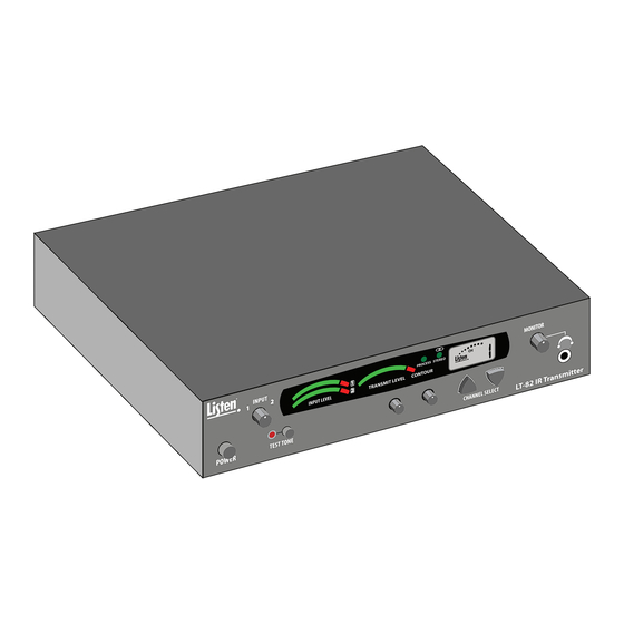
LT-82 Stationary IR Transmitter
LA-140 Stationary IR Radiator
© 2015 Listen Technologies Corporation
®
All Rights Reserved
For further details regarding use, adjustment, or programming of your Listen Technologies products visit
our website at www.listentech.com/support-manuals or contact us at +1.801.233.8992 or 1.800.330.0891.
l
1
Advertisement
Table of Contents

Related Manuals for Listen LT-82


Summary of Contents for Listen LT-82
-
Page 1: Installation And Operation
LT-82 Stationary IR Transmitter LA-140 Stationary IR Radiator © 2015 Listen Technologies Corporation ® All Rights Reserved For further details regarding use, adjustment, or programming of your Listen Technologies products visit our website at www.listentech.com/support-manuals or contact us at +1.801.233.8992 or 1.800.330.0891. -
Page 2: Table Of Contents
Stationary Infrared Table of Contents Design Guide Infrared Technology Overview System Overview Designing a System Design Tools LT-82 Stationary IR Transmitter Specifications Block Diagram Quick Reference Page Setup and Operating Instructions Accessories for LT-82 LA-140 IR Radiator Specifications Quick Reference Page... -
Page 3: Infrared Technology Overview
This is because the IR signal is being reflected in many different directions, increasing coverage. • Listen Technologies systems use higher modulation frequencies that make the system less susceptible to light interference from fluorescent lights and other sources. However, the system is not immune from interference from sources that create IR light such as sunlight and plasma displays. -
Page 4: System Overview
The radiator is powered from the power supply at the transmitter. This power supply can supply enough power for the LT-82 and up to two LA-140 radiators. If you need more than two radia- tors, you will need more power supplies. -
Page 5: System Overview
System Overview Multiple Channel System A multiple channel system consists of two to four LT-82 transmitters and one or more radiators. The diagram below shows such a system with two radiators. The radiators are powered from the power supply from the first transmitter. - Page 6 Each LT-82 transmitter used can power two LA-140 radiators Each LT-82 transmitter used can power up to two LA-140 radiators. If you design a system that requires more radiators than the transmitters can power, you need to order additional LA-205 power supplies. Each LA-205 can power up to two LA-140 Radiators.
-
Page 7: Designing A System
Designing a System Determine the number of audio channels You will need to order one LT-82 transmitter for each audio channel. The Listen system can deliver up to four audio channels simultaneously. Determine the room size and shape You should either measure the room or use the architect’s plans to obtain this information. - Page 8 Designing a System Horizontal Polar Pattern Single Channel System Vertical Polar Pattern Single Channel System...
- Page 9 Designing a System It is a good idea to provide over-lapping coverage (like in a sprinkling system) of the signal whenever possible to ensure that the signal does not have drop outs. In addition, you should provide special radiator coverage for shaded areas such as under a balcony or in the front of a room where the front mounted radiators do not provide enough coverage.
- Page 10 Designing a System If there is an area within a room (such as under a balcony) that is shielded from the main radiation pattern, you will need to provide additional radiator(s) to cover this area.
- Page 11 Radiator Mounting Angle The mounting system for Listen Technologies LA-140 radiators allow you to mount the radiator in 15 degree increments. The best angle depends on the shape of the room and the orientation of the radiator to the seats...
- Page 12 Designing a System Determine the number of radiators required Determine the number of radiators required based on the size and shape of the room. Based on step two, it is recommended that you draw the room out indicating the location of each radiator in the room and cable runs from the transmitter(s) and power supplies (if any) to the radiator.
- Page 13 Designing a System Complete the system layout worksheet Complete the system layout worksheet for Power and RF cable lengths, delay compensation, required number of power supplies, and height and angle of radiators. Refer to the system layout worksheet example below.
- Page 14 Draw a connecting line from the power supply output Draw a connecting line from the power supply output of the LT-82 transmitter(s) and the LA-205 power supplies to each of the radiators. Keep in mind that each transmitter and power supply can power up to two LA-140 radiators.
- Page 15 RF cable for multiple channel installation interconnections. You do not need to order this cable. Transmitter Rack Mounting Fill in the number of rack mounting kits required. One rack mount kit can mount two LT-82 transmitters. Radiators Fill in the number of each type of radiator required. Each radiator comes with mounting brackets for most...
- Page 16 From the System Layout Worksheet, insert the cable lengths for the preassembled coaxial RF cables (LA-391) and CAT-5 power cables (LA-393). Other Accessories For US customers, Listen Technologies offers the ADA Compliance Signage Kit (LA-304). This aids in complying with US ADA regulations.
- Page 18 System Layout Worksheet...
-
Page 21: Stationary Ir Transmitter
System Materials Worksheet Stationary IR Transmitter Power Euro Cord Transmitters Part LT-82-01 LT-82-02 LT-82-03 Number Quantity Universal Rack Mount Kit (Mounts two LT-82 units) Part Transmitter Rack LA-326 Number Mounting Quantity Stationary IR Radiator Color Grey White Part Radiators LA-140-GY... - Page 22 LT-82 Package Contents • LT-82 IR Transmitter • LA-205 Power Supply • LA-89 IR Interconnection Cable • IR System Design Guide and User’s Manual • LT-82 Quick Reference Card LT-82 IR Transmitter LA-89 IR Interconnection Cable LA-205 Power Supply Listen Configurations •...
-
Page 23: Specifications
The device shall have an audio processor that is capable of automatic gain control and limiting. The transmitter shall provide power for up to two radiators over CAT-5 cable. The LT-82 is specified. -
Page 24: Block Diagram
LT-82 Block Diagram POWER 3.5MM Stereo CHANNEL SELECT HEADPHONE Universal Power Supply 115/230VAC LA-205 Volume 50/60hz 30VDC, 1.5A (provided) Down Power Supply CPU Module Transmit Level Automatic Terminal Meter Listen LCD Display Overload CAT5 Backlit Protection DC Out Compression Ratio... -
Page 25: Quick Reference Page
Input 2 mixed audio outputs Power Outputs: Can be used to power up to two radiators Channel Display: Displays what channel the LT-82 is currently on RF output indicator: Indicates transmitter is outputting RF Program Mode: Indicates the unit is in program mode... -
Page 26: Setup And Operating Instructions
Remove outer packaging and plastic cover. Verify all components are present and no physical damage has occurred to the product. Mount LT-82(s) in Rack (if desired) If rack mounting the transmitter(s), install the optional rack mount kit (part LA-326) according to the instructions included with the kit. - Page 27 Power Output to the radiator Power Input with CAT-5 cable. NOTE: A maximum of two radiators can be powered by each LT-82. It is important not to exceed powering more than two radiators per transmitter or external power supply.
- Page 28 LT-82 Setup and Operating Instructions Select Operating Channel Select the operating channel Select the operating channel (1-4). For single channel systems any channel can be used. In multi-channel systems each transmitter must be on a different channel. Down Button Channel select buttons...
- Page 29 LT-82 Setup and Operating Instructions Connect Audio Inputs The LT-82 has two audio input options: Input 1 and Input 2. Input 1 is a balanced connection using either an XLR or 1/4” phono connector. Input 2 has two unbalanced mixing phono connectors. Use Input 1 if you are using a microphone or if you have a balanced connection such as from a professional audio mixer (you can also use Input 1 for unbalanced connections).
- Page 30 Process mode is used for Audio Gain Control (AGC). With the process mode enabled, the LT-82 will automatically adjust for inconsistent signal input levels by raising or lowering the signal level accordingly to provide a consistent sound output level. This feature should be used in applications where a consistent sound level is important and the input levels vary substantially.
-
Page 31: Accessories For
Accessories for LT-82 Accessories LA-326 Universal Rack Mounting Kit Will mount up to two LT-82 units LA-112 LA-70 RG-58 50 Ohm Coaxial Cable CAT-5 Cable Specify length Specify length LA-115 LA-127 LA-391 RG-58 BNC to RG-58 BNC Connector RG-58/50 Ohm Coaxial Cable... - Page 32 Coaxial RG-58 (25 feet) Universal Bracket CAT-5 (25 feet) Tilt Bolt Hollow Wall Anchors with Screws Tilt Arm “A” Tilt Arm “B” Universal Stand Nut Wall Box Plate Mounting Screws Wall Box Plate Listen Configurations • LA-140-GY (grey) • LA-140-WH (white)
-
Page 33: Specifications
The radiator shall come in a white or grey color and shall include all of the mounting hardware capable of mounting the radiator on a wall, on a ceiling, in a corner, on a desk, on a mic stand, or on a tripod. The Listen LA-140 is specified. Specifications... - Page 34 Default: ON Delay Compensation Switch: Adjust the amount of signal delay from the radiator here. In single Listen Mode (SW2): If using a LA-140 Radia- radiator systems the position of tor with another manufacturer’s transmit- Termination Switch: If there is no...
-
Page 35: Connect Power
RF Signal on coaxial cable Connect Power Each radiator must be supplied DC power via CAT-5 cable. One LT-82 Transmitter can power up to two radiators, also up to two radiators can be powered using an “IR Extended Power Supply” (Listen part number LA-205). - Page 36 LA-140 Setup and Operating Instructions Set Delay Compensation Switch Single Radiator Systems The position of the delay compensation switch does not matter in single radiator systems. Multiple Radiator Systems It is necessary to select the correct delay compensation switch setting for each radiator to ensure that each radiator transmits the same signal at exactly the same time in an overlapping ,multiple radiator system.
-
Page 37: Led Indications
LA-140 Setup and Operating Instructions Listen Mode Switch (SW2) If using a Listen LT-82 Transmitter with the Listen LA-140 Radiator leave this switch in the “ON” position. If you are using the Listen LA-140 Radiator with another manufacturer’s transmitter/modulator set this switch to the “OFF”... -
Page 38: Mounting Your Radiator
LA-140 – Mounting your Radiator Overview There are several different configurations that the radiator can be mounted in. All of them except for the “Dual Radiator Mounting Configurations” can be accomplished using the mounting hardware included with the LA-140 IR Radiator Kit (the LA-342 Dual Mounting Bracket is not included with the kit but is required for mounting two radiators side-by-side). - Page 39 LA-140 – Mounting your Radiator Wall Box Mounting The wall box mount is a preferred mounting option for the LA-140 IR Radiator. The wall box mount allows secure mounting of the radiator as well as for allowing the necessary cables to be placed inside the wall. Pieces Used: •...
- Page 40 LA-140 – Mounting your Radiator Pull CAT-5 and Coaxial cables through (if necessary) Pull CAT-5 and Coaxial cables through hole in Wall Box Plate Determine correct angle Determine correct angle setting to use for the radiator, see page 11 of designing a system. Attach Radiator to Wall Box Plate Attach Radiator to Wall Box Plate using Tilt Arm “A”...
- Page 41 LA-140 – Mounting your Radiator Hollow Wall Mounting A hollow wall installation is not as preferrable as a wall box installation but can be done without problems. The hollow wall installation still requires the Wall Box Plate to be used. Pieces Used: •...
- Page 42 LA-140 – Mounting your Radiator Attach Tilt Arm “B” Attach Tilt Arm “B” to Swing Arm of radiator (swing arm comes attached to rear of radiator) using included Mounting Hard- ware Screws. Any of the seven holes in Swing Arm can be used for this. Pull CAT-5 and Coaxial cables through (if necessary) Pull CAT-5 and Coaxial cables through hole in Wall Box Plate.
- Page 43 LA-140 – Mounting your Radiator Attach Safety Mounting Cable The radiator has a safety cable attached to the top of the swing arm. This cable must be attached to a secure base to prevent the radiator from falling in the event of a mounting hardware component failing. Possible injury to persons and damage to the radiator is prevented by securely attaching this cable to a base.
- Page 44 LA-140 – Mounting your Radiator Corner Mounting The radiator is mounted in the corner of a room with or without a wall box available for this use. A wall box must be at least four inches from the corner if using for this install. Pieces Used: •...
- Page 45 LA-140 – Mounting your Radiator Attach Corner Mount Bracket Attach Corner Mount Bracket to Wall Box Plate using included Mounting Harware Screws. Use all four available holes to ensure a secure attachment. Attach Tilt Arm “A” Attach Tilt Arm “A” to Corner Mount Bracket. Determine correct placement of Tilt Arm “A” by holding Radiator up to Corner Mount Bracket and determining desired position in corner.
- Page 46 LA-140 – Mounting your Radiator Pull CAT-5 and Coaxial cables through Pull CAT-5 and Coaxial cables through hole in Wall Box Plate (if necessary). Determine correct angle Determine correct angle setting to use for the radiator, see page 11 of designing a system. Attach Radiator to Corner Mount Bracket Attach Radiator to Corner Mount Bracket using Tilt Arm “A”...
- Page 47 LA-140 – Mounting your Radiator Attach Safety Mounting Cable The radiator has a safety cable attached to the top of the swing arm. This cable must be attached to a secure base to prevent the radiator from falling in the event of a mounting hardware component failing. Possible injury to persons and damage to the radiator is prevented by securely attaching this cable to a base.
- Page 48 LA-140 – Mounting your Radiator Ceiling Mounting Description: Radiator is mounted on the ceiling with or without a wall box available for this use. Pieces Used: • Wall Box Plate • Hollow Wall Mounting Screws (if attaching to wall box) or Hollow Wall Anchors with Screws (if attached to hollow wall) •...
- Page 49 LA-140 – Mounting your Radiator Attach Tilt Arm “A” Attach Tilt Arm “A” to Wall Box Plate. Attach Tilt Arm “A” in such a manner that it sits across Wall Box Plate using Mounting Hardware Screws, not up and down on plate. Attach Tilt Arm “B”...
- Page 50 LA-140 – Mounting your Radiator Attach Radiator to Wall Box Plate using Tilt Arm “A” and Tilt Arm “B” Attach Radiator to Wall Box Plate using Tilt Arm “A” and Tilt Arm “B.” Use the Tilt Bolt to fasten the tilt arms together. ATTENTION: Note the angle measurements on Tilt Arm “B”...
- Page 51 LA-140 – Mounting your Radiator Desk/Table Mounting Radiator is mounted to a support bracket that can be set on any flat surface. This is a flexible and non-permanent mounting strategy. Pieces Used: • Universal Bracket Universal Bracket • Tilt Arm “A” Tilt Bolt •...
- Page 52 LA-140 – Mounting your Radiator Determine correct angle Determine correct angle setting to use for the radiator, see page 11 of designing a system. Attach Radiator to Desk/Mic Stand Attach Radiator to Desk/Mic Stand using Tilt Arm “A” and Tilt Arm “B.” Use the Tilt Bolt to fasten the tilt arms together. ATTENTION: Note the angle measurements on Tilt Arm “B”...
- Page 53 LA-140 – Mounting your Radiator Microphone Stand Mounting Radiator is mounted on a standard microphone stand. Pieces Used: • Universal Bracket Universal Bracket Tilt Bolt • Universal Stand Nut Universal Stand Nut • Tilt Arm “A” • Tilt Arm “B” •...
- Page 54 LA-140 – Mounting your Radiator Determine correct angle setting Determine correct angle setting to use for the radiator, see page 11 of designing a system. Attach Radiator to Desk/Mic Stand Attach Radiator to Desk/Mic Stand using Tilt Arm “A” and Tilt Arm “B.” Use the Tilt Bolt to fasten the tilt arms together.
- Page 55 LA-140 – Mounting your Radiator Tripod Stand Mounting Radiator is mounted on a tripod stand. If Listen part number LA-337 is used the radiator can be mounted up to nine feet high. Pieces Used: Universal Bracket • Universal Stand Nut...
- Page 56 LA-140 – Mounting your Radiator Attach Tilt Arm “B” Attach Tilt Arm “B” to Swing Arm of radiator (swing arm comes attached to rear of radiator) using included mounting hardware screws. The bottom hole in Swing Arm must be used for this install. Determine correct angle Determine correct angle setting to use for the radiator, see page 11 of designing a system.
- Page 57 Dual Radiator Mounting It is possible to mount two Listen LA-140 Radiators either side by side or on top of each other using the LA-342 Dual Radiator Mounting Bracket (sold separately). The mounting strategy is very similar to all of the previous scenerios except you will be working with two radiators connected together.
-
Page 58: Accessories For La-140
CAT-5 Cable are using more than two LA-140 -includes RG-58 coaxial cable and CAT-5 cable to specify length radiators per LT-82 transmitter or if you interconnect the two radiators wish to remote power the radiator(s). LA-127 LA-115... -
Page 59: Troubleshooting
Troubleshooting Troubleshooting I believe my radiator has power but none of the LEDs on the front are on. SW1 has been turned OFF. Turn this switch to the ON position for verification of power and carrier. My radiator is not radiating a signal. If there is no audio at the transmitter for 30 minutes, the radiator(s) will stop radiating to conserve the life of the radiator diodes. -
Page 60: Frequently Asked Questions
Frequently Asked Questions Frequently Asked Questions How many radiators can an LT-82 power? Up to two radiators can be powered using an LT-82. You must use an external power supply (LA-205) for more radiators. How many radiators can an LA-205 power? Up to two radiators can be powered using an LA-205 external power supply. - Page 61 Utah. In the first ninety days after purchase, any defective product will be replaced with a new unit. After 90 days, Listen will, at its own discretion either repair or replace transmitters and receivers with a new unit or a unit of similar type and condition. Product that is not covered under warranty shall be repaired or replaced with a unit of similar type and condition based on a flat fee.
- Page 62 Listen Technologies Corporation 14912 Heritage Crest Way Bluffdale, Utah 84065-4818, U.S.A. +1.801.233.8992 +1.800.330.0891 North America +1.801.233.8995 www.listentech.com Printed in the United States of America © 2015 Listen Technologies Corporation All Rights Reserved 20150709 ®...
Need help?
Do you have a question about the LT-82 and is the answer not in the manual?
Questions and answers