Table of Contents
Advertisement
Quick Links
Download this manual
See also:
User Manual
Advertisement
Table of Contents

Related Manuals for Abus TVAC80020B


Summary of Contents for Abus TVAC80020B
- Page 1 TVAC80020B User guide Version 08/2012 Original user guide in English. Retain for future reference!
- Page 2 ABUS Security-Center GmbH is not liable or responsible for direct or indirect damage resulting from the equipment, performance and use of this product. No forms of guarantee are accepted for the contents of this...
- Page 3 English Explanation of symbols The triangular high voltage symbol is used to warn of the risk of injury or health hazards (e.g. caused by electric shock). The triangular warning symbol indicates important notes in these operating instructions which must be observed. This symbol indicates special tips and notes on the operation of the unit.
- Page 4 English Wireless transmission The wireless range depends on a variety of environmental factors. The local conditions at the installation site may have a negative impact on the range. When there are no obstructions between the receiver and transmitter, a range of up to 150m is possible, but this range will be considerably less within buildings. The following environmental conditions compromise both the range as well as the frame rate: Mobile communication masts, high-tension pylons, electrical wires, ceilings and walls, devices with the same or an adjacent wireless frequency.
-
Page 5: Table Of Contents
English Contents 1. Intended use ......................... 6 2. Scope of delivery ......................6 3. Features and functions ....................6 4. Device description ....................... 7 Guide to the front of the monitor ..................7 Guide to the rear of the monitor ..................8 Guide to the connections on the monitor ............... -
Page 6: Intended Use
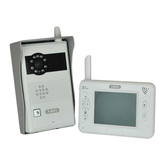
English 1. Intended use Digital wireless video intercom system, comprised of a weatherproof housing and a 3.5" LCD monitor, each with a hands-free speaker and power supply unit. You can install the system next to your door bell and connect it to your door opener. The compact 3.5" LCD color monitor is portable, meaning you do not have to walk to the intercom. -
Page 7: Device Description
English 4. Device description 4.1 Guide to the front of the monitor Display of the current charge level: Red: Battery low Battery status display Green: Charging Off: Battery fully charged Device status display Blue: Switch device on PWR / REC Off: Switch device off Flashes 3x per sec.:... -
Page 8: Guide To The Rear Of The Monitor
English 4.2 Guide to the rear of the monitor Antenna Stand 4.3 Guide to the connections on the monitor Power supply 5 VDC / 1 A (DC, 14.5 x 4.8 mm) Output for displaying the screen image on a different device AV output using an RCA cable (not included) SD card slot... -
Page 9: Guide To The Door Station
English 4.4 Guide to the door station Antenna Infrared LED Photo sensor Loudspeaker Microphone Lens Housing for attachment Bell button When the bell button is pressed, the monitor is activated. To connect the door station to the monitor, the pairing Pairing button button must be pressed. -
Page 10: Guide To The Cable Connections
English 4.5 Guide to the cable connections Cable lug with connecting cable for the door opener Cable lug contacts For connection to a door opener already installed Stripped cable ends For connection to the terminal block in the door station Round socket with connecting cable for power supply unit Connected to the connecting cable for the power supply Round socket... -
Page 11: Installation
English 5. Installation 5.1 Installation the door station To install the door station, please proceed as described in the following: Preparation Please remove the rear cover of the door station and insert 6 AA batteries. Make sure the polarity is correct. -
Page 12: Assembling The Door Station
Æ TVAC80020 More Information: www.abus.com 5.2 Assembling the door station Use the door bracket to help you find a suitable place for installation. Use the drill holes to mark the surface, and drill the holes. Insert the wall plugs provided before attaching the bracket using the screws. -
Page 13: Installing The Monitor
English 5.3 Installing the monitor Connect the power supply unit to the monitor. Switch the device on. To do so, press the power button. You can now connect the monitor to the door station. To do so, please proceed as follows: When the menu item “Camera set up”... -
Page 14: Operation
English 6. Operation To switch the monitor ON / OFF, press and hold the power button for at least 2 seconds. After each start, the monitor will switch to the live cast, selecting the last viewing settings. If the symbol is displayed, then the SD card was identified correctly by the monitor and is functioning properly. -
Page 15: Main Menu
English 6.2 Main menu Press the MENU button to enter the main menu. You can navigate between the individual menu items using the arrow buttons. Important: Please note: The symbols will be hidden automatically after being displayed for 10 seconds You can choose between the following: Camera settings: Camera brightness... -
Page 16: Camera Settings
English 6.3 Camera settings Camera brightness To change the camera brightness level, press the OK button which appears under the menu item “Camera brightness”. A selection bar with settings from 0 to 9 appears. Settings can be changed using the ◄► buttons, and be confirmed by pressing the OK button. -
Page 17: Event List
English SD Card Overwrite = SD card circular buffer Use the ◄► buttons to activate the SD card circular buffer (ON) or to deactivate it (OFF). Confirm your selection by pressing the OK button. The circular buffer is activated by default. Important: When the memory capacity is reached, the monitor will continue to record, and will delete the oldest recordings on the... -
Page 18: System Settings
English 6.6 System settings Time setting = settings for date and time Press the ► button to toggle between year/month/day/hour/minute. Use the ▲▼ buttons to adjust the values. Confirm your input by pressing the OK button. Software version This indicates the version of the software being used by the door station and the monitor. -
Page 19: Maintenance And Cleaning
English 7. Maintenance and cleaning 7.1 Maintenance Examine the technical safety of the product regularly, e.g. check the housing for damage. If it seems that it may no longer be possible to operate the device safety, stop using the product and protect it from unintentional use. -
Page 20: Technical Data
English 9. Technical data Model number Door station 3.5" LCD monitor Frequency 2.4 GHz Modulation GFSK Transmission power 13dBm Sensitivity -75dBm Wireless range 150 m* DC voltage supply 15V DC / 1.5 A 5V DC / 1 A Power consumption Max.
Need help?
Do you have a question about the TVAC80020B and is the answer not in the manual?
Questions and answers