Table of Contents
Advertisement
Advertisement
Table of Contents

Related Manuals for Xray T1


Summary of Contents for Xray T1
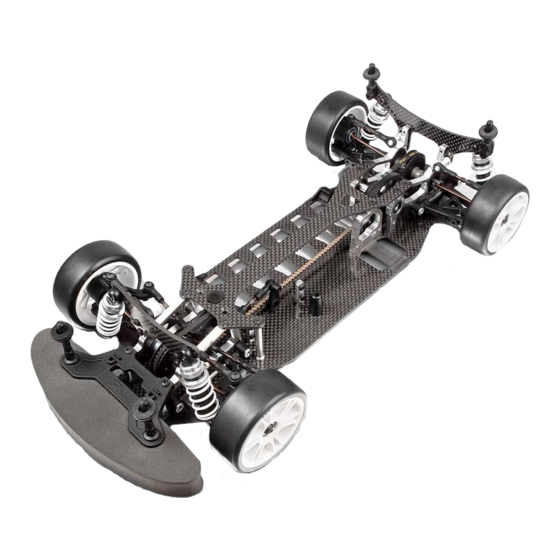
- Page 2 XRAY T1 Factory Kit 2005 The new XRAY T1 Factory Kit '05 (T1FK'05) is the 5th generation of Many new and updated features are present on the T1FK'05 to XRAY's extremely successful T1 family of 1/10-scale on -road electric optimize performance, while reducing unnecessary weight and touring cars.
-
Page 3: Table Of Contents
ALU SUSP . ADJUSTABLE BULKHEADS T1FK'05 (4) The XRAY T1FK'05 comes partially pre-assembled. Before starting assembly, disassemble the chassis parts, noting the position and orientation of the parts, particularly the bulkheads. Keep the parts, including the screw hardware, close at hand. In the assembly steps that follow, each section begins with a parts list. Parts indicated... - Page 4 CARBIDE BALL-BEARING AXIAL F3-8 3 x 8 x 3.5 30 5082 DIFF WASHER 17x23x1 (2) 93 0508 BALL-BEARING MR85ZZ 5x8x2.5 (2) 30 5102 XRAY MULTI-DIFF™ T1FK'05 96 3030 CONE WASHER ST 3x8x0.5 (10) 30 5131 INNER DRIVESHAFT ADAPTER - T1FK'05 - SPRING STEEL (2) 96 6080...
-
Page 5: Ball Differential & Front Multi-Diff
™ BALL DIFFERENTIAL & FRONT MULTI-DIFF The ball differential is pre-assembled at the factory. ˜ Follow these steps if you need to clean or rebuild the ball differential. 930508 1. Hold the short diff shaft with the installed pulley facing up. Place a #930508 (BB 5x8) BB 5x8 ™... -
Page 6: Rear Transmission
2. REAR TRANSMISSION 965050 981210 305575 305002 305442 941015 302040 302070 302074 302080 940509 902312 305431 309319 902305 307312 305516 901408 305784 302032 305787 (OPTION) 940610 305790 (OPTION) 302070 902310 901308 303159 301112 302040 302002 309319 302032 904306 904306 30 2032 ALU NUT FOR SUSP . -
Page 7: Front
REAR TRANSMISSION 1. Attach #305784 spur gear to #305516 layshaft with three #902305 (SH M3x5) screws. — 981210 ™ P 2x10 2. Press a #981210 (P 2x10) pin into the layshaft hole closest to the spur gear. – 3. Slide a 20T pulley onto the layshaft, and seat it over the pin. 4. -
Page 8: Rear Suspension
3. REAR SUSPENSION 902308 902306 303093 303031 303220 902310 302615 307454 302662 303350 941015 967100 305240 305230 941015 307320 305311 901305 305321 981210 30 2615 ADJ. TURNBUCKLE L/R 30 MM - SPRING STEEL (2) 30 7320 REAR PIVOT PIN FOR C-HUB - SPRING STEEL (2) 30 2662 BALL JOINT 5 MM - OPEN (6) 30 7454... - Page 9 REAR SUSPENSION Install both rear uprights by performing the following steps. DETAIL 1. Place the driveshaft plastic cap into the diff outdrive slot. 901305 Insert the rear upright into the end of the rear lower arm as SB M3x5 shown. Align the hole in the bottom of the rear upright and —...
-
Page 10: Front Transmission
BALL DIFF. WITH LABYRINTH COVERS™ - (FACTORY KIT) 90 1408 HEX SCREW SB M4x8 (10) 30 5102 XRAY MULTI-DIFF ™ T1FK'05 (SET) 90 2310 HEX SCREW SH M3x10 (10) 30 5431 HIGH-PERFORMANCE KEVLAR DRIVE BELT FRONT 3 x 507 MM 1. -
Page 11: Front Transmission
FRONT TRANSMISSION The left and right front lower arms are mirror images. 1. Thread a #901408 (SB M4x8) downstop adjustment screw into the 901408 innermost hole at the rear of each front lower arm, closest to the pivot pin SB M4x8 –... -
Page 12: Front Suspension
5. FRONT SUSPENSION 302284 302260 303220 303240 302096 902310 902312 307454 302282 302290 960030 307220 302630 902312 902310 302662 901304 902306 967100 941015 305230 302250 941015 305240 305321 981210 305311 30 2096 SHOCK TOWER FRONT - FACTORY KIT 30 5321 DRIVE SHAFT - 51 MM - SPRING STEEL - (FACTORY KIT) (2) 30 2250 COMPOSITE STEERING BLOCK RIGHT FOR C-HUB SUSP . -
Page 13: Front
FRONT SUSPENSION TO INSTALL A SNAP RING: TO REMOVE A SNAP RING: Place the hex portion of the wheel axle flat on a table. Place the hex portion of the wheel axle flat Put one end of the snap ring into the groove on the on a table. -
Page 14: Upper Deck T1Fk'05 - Cnc Machined
6. STEERING 904306 301164 306510 904306 902310 307454 902312 302551 302662 930407 307454 902310 307454 302662 302580 302615 302502 or 302582 302502 302611 902312 302662 307454 902312 FACTORY PRE-ASSEMBLED 30 2502 CENTRAL SERVO SAVER T1FK'05 (SET) 90 2310 HEX SCREW SH M3x10 (10) 30 2551 SERVO SAVER PLASTIC COVER - ECCENTRIC (2) 90 2312... -
Page 15: Steering
STEERING 1. Attach the left and right steering rods to the servo saver. — Pass a #902312 (SH M3x12) screw upward through the following parts: • #307454 pivot ball • steering rod inner ball joint (on long end) 902312 Thread the screw into the inner hole on the bottom of the servo saver. SERVO LINK SH M3x12 Tighten until the pivot ball snaps into the ball joint, and then tighten the... - Page 16 SILICONE O-RING 3.1x1.6 (10) Properly functioning shocks are very important to the performance of your car. This XRAY shock set contains parts to build four externally-adjustable or non-adjustable shocks. Both adjustable and non-adjustable shocks feature XRAY's unique keying system that positively locks the pistons to the shock rods.
-
Page 17: Shock Absorbers
SHOCK ABSORBERS 1. Insert the larger #970050 (O 5x1) O-ring onto the shock body, until it seats around the shock body extension. 2. Lubricate the small #971031 (O 3.1x1.6) O-ring with a drop or two of shock oil. Taking care not to rip or damage the O-ring, ˜... -
Page 18: Rear Assembly
98 1210 PIN 2x10 (10) 90 2306 HEX SCREW SH M3x6 (10) 90 2308 HEX SCREW SH M3x8 (10) 30 8300 XRAY SHOCK ABSORBER-SET 4-STEP (2) Assemble TWO rear body posts by performing the following ™ steps. ˜ 902308 SH M3x8 1. -
Page 19: Front Assembly
HEX SCREW SFH M3x10 - SILVER (10) 98 1210 PIN 2x10 (10) 30 8300 XRAY SHOCK ABSORBER-SET 4-STEP (2) 1. Place a #960030 (N M3) nut into the hex recess atop the #301200 lower bumper. 960030 2. Place the lower bumper onto the front of the chassis. -
Page 20: Final Assembly
9. FINAL ASSEMBLY NOT INCLUDED 303050 902306 904306 NOT INCLUDED 902308 FROM SERVO NOT INCLUDED 306200 904306 904306 30 3050 CENTRAL MOTOR MOUNT 90 2306 HEX SCREW SH M3x6 (10) 30 5716~34 PINION GEAR ALU HARD COATED 48T (OPTION) 90 2308 HEX SCREW SH M3x8 (10) 30 6200 ALU SERVO MOUNT (2) -
Page 21: Accessory Assembly
ACCESSORY ASSEMBLY NOT INCLUDED TAPE 306131 NOT INCLUDED NOT INCLUDED 306310 306300 NOT INCLUDED 309400 TIRES & INSERTS NOT INCLUDED 803001 309310 904306 904308 30 6131 SET OF BATTERY BACKSTOPS T1FK'05 30 9400 BODY CLIP (8) 30 6162 6-CELL BATTERY STRAP T1FK'05 (OPTION) 80 3001 HUDY 24 MM WHEELS STARBURST - WHITE (4) 30 6300... - Page 22 ACCESSORY ASSEMBLY The XRAY T1FK'05 is a competition racecar, and therefore does not come supplied with tires and inserts. Check with racers at tracks you attend to determine the best tire/insert combinations. To install rubber tires and inserts on the supplied wheels, —...
- Page 23 - In places where children and people gather XRAY guarantees this model kit to be free from defects in both material and - In residential districts and parks workmanship. The total monetary value under warranty will in no case exceed the - In limited indoor spaces cost of the original kit purchased.
- Page 24 XRAY MODEL RACING CARS XRAY MODEL RACING CARS XRAY MODEL RACING CARS P .O.BOX 103 P .O.BOX 103 P .O.BOX 103 911 50 TREN 911 50 TRENČÍ ČÍN 911 50 TRENČÍN SLOVAKIA, EUROPE SLOVAKIA, EUROPE SLOVAKIA, EUROPE PHONE: ++421 905 402724...
Need help?
Do you have a question about the T1 and is the answer not in the manual?
Questions and answers