Dell PowerConnect 2808 User Manual
Webmanaged gigabit ethernet switches
Hide thumbs
Also See for PowerConnect 2808:
- Getting started manual (260 pages) ,
- Release notes (6 pages) ,
- User manual (186 pages)

Related Manuals for Dell PowerConnect 2808


Summary of Contents for Dell PowerConnect 2808
-
Page 1: User Guide
Dell™ PowerConnect™ 28xx Systems User Guide w w w . d e l l . c o m | s u p p o r t . d e l l . c o m... - Page 2 Trademarks used in this text: Dell, Dell OpenManage, the DELL logo, Inspiron, Dell Precision, Dimension, OptiPlex, PowerConnect, PowerApp, PowerVault, Axim, DellNet, and Latitude are trademarks of Dell Inc. Microsoft and Windows are either trademarks or registered trademarks of Microsoft Corporation in the United States and/or other countries.
-
Page 3: Table Of Contents
......PowerConnect 2808 ...... - Page 4 Power Connectors ....... Internal Power Supply Connector ....3 Installing the PowerConnect Device .
- Page 5 ........5 Using Dell OpenManage Switch Administrator .
- Page 6 Defining SNMP Parameters ......Defining SNMP Global Parameters ....Defining Communities .
- Page 7 Configuring VLANs ......Defining VLAN Members ..... . . VLAN Port Membership Table .
- Page 8 Using the CLI ....... . Command Mode Overview ..... . User EXEC Mode .
-
Page 9: Introduction
Introduction This User’s Guide contains the information needed for installing, configuring and maintaining the PowerConnect 2808, PowerConnect 2816, PowerConnect 2824, and PowerConnect 2848 Web- managed Gigabit Ethernet switches. The PowerConnect 28xx switches can be used to connect workstations and other network devices, such as: •... -
Page 10: Powerconnect 2824
The following figure illustrates the PowerConnect 2848 front panel. Figure 1-4. PowerConnect 2848 Front Panel The PowerConnect 2848 supports the following ports: • 48 Gigabit Ethernet copper ports • 4 SFP combo ports (1000BASE-SX or 1000BASE-LX) Dell PowerConnect 28xx Systems User Guide... -
Page 11: Summary Of Powerconnect Models
On half-duplex links, the receiving port prevents buffer overflows by occupying the link so that it is unavailable for additional incoming traffic. The user may enable or disable this feature on a per-port basis. The default status on all ports is set to OFF. Dell PowerConnect 28xx Systems User Guide... - Page 12 Cable analysis is available on Copper Cables (10BASE-T/100BASE-T/1000BASE-T), and is only done when the link is down. When the system initiates a cable-testing operation, upon explicit user action, the following parameters are detected: • Cable Type and Status • Cable Length • Fault-Distance Dell PowerConnect 28xx Systems User Guide...
-
Page 13: Mac Address Supported Features
MAC Address Supported Features MAC Address Capacity Support The PowerConnect 2808, 2816, 2824 switches support a total of 8K MAC addresses, and the PowerConnect 2848 supports a total of 16K MAC addresses. Auto-Learning MAC Addresses The switch enables MAC address auto-learning from incoming packets. The MAC addresses are stored in the Bridging Table. -
Page 14: Vlan Supported Features
The PowerConnect 28xx switches support up to eight aggregated links. Each of the eight aggregated links may be defined with up to eight member ports to form a single Link Aggregated Group (LAG). The benefits of this facility are: • Fault tolerance protection from physical link disruption Dell PowerConnect 28xx Systems User Guide... -
Page 15: Spanning Tree Protocol Features
Rapid Spanning Tree (RSTP) detects uses of network topologies to enable faster convergence, without creating forwarding loops. STP Root Guard Root guard restricts the interface from functioning as the root port for the switch Dell PowerConnect 28xx Systems User Guide... -
Page 16: Class Of Service (Cos) Features
The switches support one RMON group for Ethernet statistics. The system provides a means to collect the statistics defined in RMON and to view the results, using the Web management interface in the system. Dell PowerConnect 28xx Systems User Guide... -
Page 17: Hardware Description
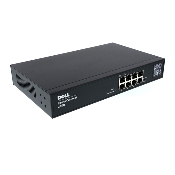
Switch Port Configurations PowerConnect 28xx Front and Back Panel Port Description The Dell™ PowerConnect™ 28xx switches use 10/100/1000BASE-T ports on the front panel for connecting to a network. The Gigabit Ethernet ports can operate at 10, 100 or 1000 Mbps. These ports support auto- negotiation, duplex mode (Half or Full duplex), and flow control. - Page 18 Figure 2-2. PowerConnect 2808 Back Panel Figure 2-3. PowerConnect 2816 Front Panel On the front panel there are 16 ports which are numbered 1 to 16, top down and left to right. On each port there are LEDs to indicate the port status.
- Page 19 For more information about management modes and transitioning between them, see "Management Modes" on page 49. Dell PowerConnect 28xx Systems User Guide...
- Page 20 The Fan LED indicates the device fan operations status, and the Power LED on the front panel indicates whether the device is powered on or not. A Mode push- Dell PowerConnect 28xx Systems User Guide...
-
Page 21: Physical Dimensions
Fans are provided on the side panel. The back panel contains an AC Power Supply Interface. The following figure illustrates the back panel of the PowerConnect 2848 device. Figure 2-8. PowerConnect 2848 Back Panel Physical Dimensions The PowerConnect 2808 switch has the following physical dimensions: • Height — 43.2 mm (1.7008 in.) •... -
Page 22: Power Led
10/100/1000BASE-T Port LEDs Each 10/100/1000BASE-T port has two LEDs. Speed/Link/Activity is indicated on the left LED and the duplex mode is indicated on the right LED. The following figure illustrates the RJ-45 10/100/1000BASE-T LEDs. Dell PowerConnect 28xx Systems User Guide... -
Page 23: Managed Mode Button
"Management Modes" on page 49. Switch Ventilation Fan The PowerConnect 2848 switch has three fans and the PowerConnect 2824 switch has one fan for system ventilation. The PowerConnect 2808 and PowerConnect 2816 devices have no internal fans. Dell PowerConnect 28xx Systems User Guide... -
Page 24: Cables, Port Connections, And Pinout Information
The RJ-45 pin number allocation for the 10/100/1000BASE-T ports is listed in the following table. Table 2-7. RJ-45 Pin Number Allocation for 10/100/ 1000BASE-T Ethernet Port Pin No Function TxRx 1+ TxRx 1- TxRx 2+ TxRx 2- TxRx 3+ Dell PowerConnect 28xx Systems User Guide... -
Page 25: Sfp Ports
Receiver ground (common with transmitter ground) Receiver ground (common with transmitter ground) Receiver ground (common with transmitter ground) Receiver inverted data out; AC coupled. Receiver non-inverted data out; AC coupled. Receiver ground (common with transmitter ground) Dell PowerConnect 28xx Systems User Guide... -
Page 26: Power Connectors
The PowerConnect 28xx supports a single internal power supply to provide power for switching operations. The internal power supply supports input voltages between 100 and 240 VAC. The AC power connector is located on the back panel of the switch. Dell PowerConnect 28xx Systems User Guide... -
Page 27: Installing The Powerconnect Device
Do not install the device in an environment where the operating ambient temperature might exceed 45ºC (113ºF). • Ensure that the airflow around the front, sides, and back of the device is not restricted. Dell PowerConnect 28xx Systems User Guide... -
Page 28: Site Requirements
1 Place the box on a clean flat surface. 2 Open the box or remove the box top. 3 Carefully remove the device from the package and place it on a secure, stable and clean surface. 4 Remove all packing material. Dell PowerConnect 28xx Systems User Guide... -
Page 29: Mounting The Device
1 Place the supplied rack-mounting bracket on one side of the device ensuring the mounting holes on the device line up to the mounting holes on the rack mounting bracket. The following figure illustrates where to mount the brackets. Dell PowerConnect 28xx Systems User Guide... -
Page 30: Installing On A Flat Surface
2 Set the device on a flat surface, while leaving 2 inches (5.08 cm) on each side and 5 inches (12.7 cm) at the back. 3 Ensure that the device has proper ventilation. Dell PowerConnect 28xx Systems User Guide... -
Page 31: Installing On A Wall
3 Insert the supplied screws into the rack-mounting holes and tighten with a screwdriver. 4 Repeat the process for the wall-mounting bracket on the other side of the device. 5 Place the device on the wall in the location where the device is being installed. Dell PowerConnect 28xx Systems User Guide... - Page 32 7 On the marked locations, drill the holes and place all plugs (not provided) in the holes. 8 Secure the device to the wall with screws (not provided). Ensure that the ventilation holes are not obstructed. Figure 3-3. Mounting Device on a Wall Dell PowerConnect 28xx Systems User Guide...
-
Page 33: Connecting The Device
1 Connect the supplied RS-232 crossover cable to the terminal running VT100 terminal emulation software. 2 Ensure that the terminal emulation software is set as follows: Select the appropriate serial port (serial port 1 or serial port 2) to connect to the console. Dell PowerConnect 28xx Systems User Guide... -
Page 34: Connecting A Device To A Power Supply
1 Connect the supplied standard AC power cable to the AC connector on the back panel. 2 Do not connect the power cable to a grounded AC outlet at this time. Connect the device to a power source in the steps detailed in Starting and Configuring the Device. Dell PowerConnect 28xx Systems User Guide... -
Page 35: Port Connections, Cables, And Pinout Information
(switch or hub) to another. Both the straight through and crossover cables are category 5. After a port is connected, its LINK indication LED is lit. Dell PowerConnect 28xx Systems User Guide... - Page 36 The RJ-45pin number allocation for the 10/100/1000BaseT ports is listed in the table following. Table 3-2. RJ-45 Pin Number Allocation for 10/100/1000BaseT Ethernet Port Pin No Function TxRx 1+ TxRx 1- TxRx 2+ TxRx 2- TxRx 3+ TxRx 3- TxRx 4+ TxRx 4- Dell PowerConnect 28xx Systems User Guide...
-
Page 37: Port Default Settings
It can be enabled per port. The back pressure mechanism prevents the transmitting side from transmitting additional traffic temporarily. The receiving side may occupy a link so it becomes unavailable for additional traffic. Dell PowerConnect 28xx Systems User Guide... -
Page 38: Switching Port Default Settings
Port speed and mode 10/100/1000BaseT copper: auto-negotiation full duplex Port forwarding state Enabled Port tagging No tagging Flow Control Back Pressure Off (disabled on ingress) MDIX (not user-configurable) On (relevant to coppers ports only) Dell PowerConnect 28xx Systems User Guide... -
Page 39: Starting And Configuring The Device
NOTE: Before proceeding, read the release notes for this product. The release notes can be downloaded from http://support.dell.com. It is recommended that you obtain the most recent revision of the user documentation from the Dell support website at http://support.dell.com. NOTE: If the device is to be used as an unmanaged switch, there is no need for a terminal connection. -
Page 40: Management Modes
Managed Mode — In this mode: – Switch can be managed through the web interface. – Managed Mode LED is ON. – Device uses the saved running configuration (if it exists) or the default configuration. Dell PowerConnect 28xx Systems User Guide... - Page 41 Managed Mode LED is OFF. – Return to Managed mode by pressing the Mode button on the device for up to 7 seconds. All modes are maintained throughout power cycles. The Managed Mode LED shows the current mode. Dell PowerConnect 28xx Systems User Guide...
-
Page 42: Transitioning Between Modes
Note the following points: • The Managed Mode LED designates whether the management interface is active on the switch. The LED is ON only in the Managed mode, and OFF in Secure and Unmanaged modes. Dell PowerConnect 28xx Systems User Guide... - Page 43 IP address using the following page: Figure 4-3. Restore Saved Configuration – Local Configuration — No saved configuration is loaded. – Server IP Address/File Name — Loads a previously saved configuration. Dell PowerConnect 28xx Systems User Guide...
-
Page 44: Booting The Device - Managed Mode
Through the Set-up wizard, as described below. NOTE: The initial simple configuration uses the following assumptions: The PowerConnect device was never configured before, and is in the same state as when you received it. • Dell PowerConnect 28xx Systems User Guide... - Page 45 Default Gateway IP address The Setup Wizard displays the following information: Welcome to Dell Easy Setup Wizard. The Setup Wizard guides you through the initial switch configuration, and gets you up and running as quickly as possible. You can skip the setup wizard, and enter CLI mode to manually configure the switch.
- Page 46 [Privilege Level 15] to this account. You can use Dell Network Manager or CLI to change this setting, and to add additional management systems. For more information on adding management systems, see the user documentation.
- Page 47 IP address you use to access the Telnet, Web interface, or SNMP interface for the switch. To setup an IP address: Please enter the IP address of the device (A.B.C.D):10.6.22.100 Please enter the IP subnet mask (A.B.C.D or nn):[255.255.255.224] Dell PowerConnect 28xx Systems User Guide...
-
Page 48: Initial Configuration Through The Web
Configuring SNMP management interface. Configuring user account..Configuring IP and subnet..Thank you for using Dell Easy Setup Wizard. Initial Configuration Through the Web The administrator can choose to perform device configuration via the web management instead of through the Set-up wizard. -
Page 49: Retrieving An Ip Address From A Dhcp Server
When using the DHCP protocol to retrieve an IP address, the device acts as a DHCP client. When the device is reset, the DHCP command is saved in the configuration file, but not the IP address. Dell PowerConnect 28xx Systems User Guide... -
Page 50: Startup Menu
2 When the auto-boot message appears, press <Enter> to get the Startup menu. The Startup menu procedures can be done using the ASCII terminal or Windows HyperTerminal. Download Software Erase Flash File Password Recovery Procedure Dell PowerConnect 28xx Systems User Guide... -
Page 51: Software Download
2 Press Y . The following message is displayed. Write Flash file name (Up to 8 characters, Enter for none.):config File config (if present) will be erased after system initialization ======== Press Enter To Continue ======== Dell PowerConnect 28xx Systems User Guide... -
Page 52: Password Recovery
Exclamation symbols indicate that a copying process is in progress. Each symbol (!) corresponds to 512 bytes transferred successfully. A period indicates that the copying process is timed out. Many periods in a row indicate that the copying process failed. Dell PowerConnect 28xx Systems User Guide... - Page 53 4 Enter the reload command. The following message is displayed: console# reload This command will reset the whole system and disconnect your current session. Do you want to continue (y/n) [n]? 5 Enter y . The device reboots. Dell PowerConnect 28xx Systems User Guide...
-
Page 54: Using Dell Openmanage Switch Administrator
Device View — Located on the right side of the home page, the device view provides an information or table area, and configuration instructions. Figure 5-1. Switch Administrator Components Table 5-1 lists the interface components with their corresponding numbers. Dell PowerConnect 28xx Systems User Guide... -
Page 55: Using The Switch Administrator Buttons
The information buttons provide access to information about the device and access to Dell Support. For more information, see "Information Buttons." The components list contains a list of the feature components. -
Page 56: Device Management Buttons
The device can be managed via web interface only in Managed mode. For more information about management modes, see "Management Modes" on page 51. 4 Click OK. The Dell PowerConnect OpenManage™ Switch Administrator home page opens. Access Levels When you login to the device, you are automatically assigned one of the following modes, based upon... - Page 57 Monitor — This is a read-only mode where you can see a subset of the interface pages, but you cannot edit them. For more information about setting the access level, see ("Defining the Local User Databases" on page 68). Dell PowerConnect 28xx Systems User Guide...
-
Page 58: Configuring System Information
The Asset page contains parameters for configuring general device information, including the system name, location, and contact, the system MAC Address, System Object ID, date, time, and System Up Time. To open the Asset page, click System General Asset in the tree view. Dell PowerConnect 28xx Systems User Guide... - Page 59 System Up Time — Specifies the amount of time since the last device reset. The system time is displayed in the following format: Days, Hours, Minutes and Seconds. For example,. Defining System Information: 1 Open the Asset page. 2 Define the relevant fields. Dell PowerConnect 28xx Systems User Guide...
-
Page 60: Viewing The Versions Page
Figure 6-3. Versions Software Version — The current software version running on the device. • • Boot Version — The current Boot version running on the device. • Hardware Version — The current hardware version. Dell PowerConnect 28xx Systems User Guide... -
Page 61: Resetting The Device
3 Click OK. The device is reset. After the device is reset, a prompt for a user name and password displays. 4 Enter a user name and password to reconnect to the Web Interface. Dell PowerConnect 28xx Systems User Guide... -
Page 62: Entering Secure Mode
Secure Mode in the tree view. Figure 6-5. Secure Mode Entering Secure Mode 1 Open the Secure Mode page. 2 Click Secure. A confirmation message displays. 3 Click OK. The device enters Secure mode. Dell PowerConnect 28xx Systems User Guide... -
Page 63: Defining Device Ip Addresses
Setting static IP Interface parameters: 1 Open the IP Interface Parameters page 2 Set the IP Address, Subnet Mask and Default Gateway. 3 Click Apply Changes. The static interface parameters are set and the device is updated. Dell PowerConnect 28xx Systems User Guide... -
Page 64: Running Cable Diagnostics
Test Result — The cable test results. Possible values are: – No Cable — – Open Cable — cable is connected on only one side. – Short Cable — OK — The cable passed the test. Dell PowerConnect 28xx Systems User Guide... -
Page 65: Viewing Optical Transceiver Diagnostics
The Optical Transceiver Diagnostics page contains fields for performing tests on Fiber Optic cables. Optical transceiver diagnostics can be performed only when the link is present. To open the Optical Transceiver Diagnostics page, click SystemDiagnostics Optical Transceiver Diagnostics in the tree view. Dell PowerConnect 28xx Systems User Guide... - Page 66 2 Click Show All. • The test is run and the Virtual Cable Test Results Table opens. Clicking Show All opens the Optical Transceiver Diagnostics Table. The Optical Transceiver Diagnostics Table contains the following columns: Dell PowerConnect 28xx Systems User Guide...
- Page 67 Data Ready — The transceiver has archived power up and data is ready. • N/A — Not Available, N/S - Not Supported, W - Warning, E - Error. Fiber Optic analysis feature works only on SFPs that support the digital diagnostic standard SFF-4872. Dell PowerConnect 28xx Systems User Guide...
-
Page 68: Managing Device Security
Remove — Removes users from the User Name list, when selected. Assigning Access Rights to a User: 1 Open the Local User Database page. 2 Select a user in the User Name field. 3 Define the fields. Dell PowerConnect 28xx Systems User Guide... - Page 69 The new user is defined, and the device is updated. Displaying the Local User Table: 1 Open the Local User Database page. 2 Click Show All. The Local User Table opens: Figure 6-11. Local User Table Dell PowerConnect 28xx Systems User Guide...
-
Page 70: Configuring Radius Global Parameters
IP Address — The list of Authentication Server IP addresses. Priority (0-65535) — Specifies the server priority. The possible values are 0-65535, where 0 is the • highest value. This is used to configure the order in which servers are queried. Dell PowerConnect 28xx Systems User Guide... - Page 71 2 Define the fields. 3 Click Apply Changes. The RADIUS setting are updated to the device. Adding a RADIUS Server: 1 Open the RADIUS Settings page. 2 Click Add. The Add RADIUS Server page opens: Dell PowerConnect 28xx Systems User Guide...
- Page 72 The Show all RADIUS Servers page opens: Figure 6-14. Show all RADIUS Servers Modifying the RADIUS Server Settings: 1 Open the RADIUS Settings page. 2 Click Show All. The RADIUS Servers List page opens. Dell PowerConnect 28xx Systems User Guide...
-
Page 73: Defining Snmp Parameters
Access rights to the SNMP agents are controlled by access strings. To communicate with the device, the Embedded Web Server submits a valid community string for authentication. To open the SNMP page, click System SNMP in the tree view. This section contains information for managing the SNMP configuration. Dell PowerConnect 28xx Systems User Guide... -
Page 74: Defining Snmp Global Parameters
3 Click Apply Changes. SNMP notifications are enabled, and the device is updated. Enabling Authentication Notifications 1 Open the SNMP Global Parameters page. 2 Select Enable in the Authentication Notifications field. 3 Click Apply Changes. Dell PowerConnect 28xx Systems User Guide... -
Page 75: Defining Communities
SNMP Admin — The management access is read-write for all MIBs, including the community table. • Remove — Removes a community, when selected. Defining a New Community 1 Open the SNMP Community page. 2 Click Add. The Add SNMP Community page opens: Dell PowerConnect 28xx Systems User Guide... - Page 76 1 Open the SNMP Community page. 2 Click Show All. The Community Table opens: Figure 6-18. Community Table Deleting Communities 1 Open the Community Table page. 2 Click Show All. The Community Table opens. Dell PowerConnect 28xx Systems User Guide...
-
Page 77: Defining Snmp Notification Recipients
Notification Version — Determines the trap type. The possible field values are: – SNMPv1 — SNMP Version 1 traps are sent. – SNMPv2 — SNMP Version 2 traps are sent. • Remove Notification Recipient — When checked, removes selected notification recipients. Dell PowerConnect 28xx Systems User Guide... - Page 78 The Notification Recipients Tables page opens: Figure 6-20. Notification Recipients Tables Deleting Notification Recipients 1 Open Notification Recipients page. 2 Click Show All. The Notification Recipients Tables page opens. 3 Select a notification recipient. Dell PowerConnect 28xx Systems User Guide...
-
Page 79: Managing Files
The File Download From Server page contains fields for downloading system image and Configuration files from the TFTP server or HTTP client to the device. To open the File Download From Server page, click System File Management File Download in the tree view. Dell PowerConnect 28xx Systems User Guide... - Page 80 Destination File Name— The destination file to which the file is downloaded. The possible field values are: – Software Image — Downloads the software image file. Boot Code — Downloads the boot file. – Dell PowerConnect 28xx Systems User Guide...
-
Page 81: Uploading Files
The File Upload to Server page contains fields for uploading the Configuration file from the device to the TFTP server. To open the File Upload to Server page, click System File Management File Upload in the tree view. Figure 6-22. File Upload to Server Dell PowerConnect 28xx Systems User Guide... -
Page 82: Restoring Default Settings
Restore Configuration Factory Defaults — Sets the device settings to their factory default values. • Restoring Default Settings 1 Open the Restore Defaults page. 2 Check the Restore Configuration Factory Defaults checkbox. 3 Click Apply Changes. The settings are restored. Dell PowerConnect 28xx Systems User Guide... -
Page 83: Defining Dhcp Server Settings
DHCP Server assumes (with a high probability) that the address is not in use and assigns the address to the requesting client. To open the DHCP Server Properties page, click System DHCP Server DHCP Server Properties in the tree view. Dell PowerConnect 28xx Systems User Guide... - Page 84 3 Optionally, select Enable in the DHCP Ping field to enable ping globally. 4 Define the number of ping retries in the DHCP Ping Retries field, or click Use Default to select the default number of two retries. Dell PowerConnect 28xx Systems User Guide...
-
Page 85: Defining Network Pool
The total lease duration is 4294967295 seconds, i.e. 49710.2696 days. Thus a lease of 49710 days, 0 hours, 0 minutes and 0 seconds is a legal value, while a lease of 49710 days, 23 hours, 59 minutes and 59 seconds results in an Out of Range alert. Dell PowerConnect 28xx Systems User Guide... -
Page 86: Excluding Addresses
By default, the DHCP Server assumes that all pool addresses may be assigned to DHCP clients. The user can specify IP addresses that must not be used. These addresses are referred to as excluded addresses. A single IP address or a range of IP addresses can be excluded. Dell PowerConnect 28xx Systems User Guide... - Page 87 The Add Excluded page opens: Figure 6-27. Add Excluded 3 Define the relevant fields. 4 Click Apply Changes. The address is excluded, and the device is updated. Deleting Excluded Addresses 1 Open the Excluded Addresses page. Dell PowerConnect 28xx Systems User Guide...
-
Page 88: Manually Allocating Ip Addresses (Static Hosts)
Client Name — Specifies the name of the client, using a standard set of ASCII characters. The client name must not include the domain name. The range is up to 32 characters. • Default Router — Specifies the default router for the DHCP static host. Dell PowerConnect 28xx Systems User Guide... - Page 89 File Name — Specifies the name of the file that is used as a boot image. The file name may contain up to 128 characters. Adding a new Static Host 1 Open the Static Hosts page. 2 Click Add. The Add Static Host page opens: Dell PowerConnect 28xx Systems User Guide...
- Page 90 The static host is added, and the device is updated. Displaying Static Hosts Tables 1 Open the Static Hosts page. 2 Click Show All. The Static Hosts Table page opens: Figure 6-30. Static Hosts Table Dell PowerConnect 28xx Systems User Guide...
-
Page 91: Address Binding
Dynamic allocation — A network device obtains a leased IP address for a specified period of time. The IP address is revoked at the end of this period and the switch must request another IP address. Dell PowerConnect 28xx Systems User Guide... -
Page 92: Defining Advanced Settings
After Reset — The future (after reset) value. • Jumbo Frames — Enables or disables the Jumbo Frames feature. Jumbo Frames enable the transportation of identical data in fewer frames. This ensures less overhead, lower processing time, and fewer interrupts. Dell PowerConnect 28xx Systems User Guide... -
Page 93: Configuring Device Switching
Voice over IP does not require authentication, while data traffic requires authentication. VLANs for which authorization is not required can be defined. Unauthenticated VLANs are available to users, even if the ports attached to the VLAN are defined as authorized. Dell PowerConnect 28xx Systems User Guide... -
Page 94: Configuring Port Based Authentication
– Enable — Enables port based authentication on the device. – Disable — Disables port based authentication on the device. • Authentication Method — The Authentication method used. The possible field values are: Dell PowerConnect 28xx Systems User Guide... - Page 95 The field default is 2 retries. Displaying the Port Based Authentication Table 1 Display the Port Based Authentication page. 2 Click Show All. The Port Based Authentication Table opens: Dell PowerConnect 28xx Systems User Guide...
- Page 96 5 Select the Copy to check box to define the interfaces to which the Port based authentication parameters are copied. 6 Click Apply Changes. The parameters are copied to the selected port in the Port Based Authentication Table, and the device is updated. Dell PowerConnect 28xx Systems User Guide...
-
Page 97: Configuring Advanced Port Based Authentication
Shutdown — Discards the packet from any unlearned source and locks the port. Ports remain locked until they are activated, or the device is reset. • Traps — Enables or disables sending traps to the host if a violation occurs. Dell PowerConnect 28xx Systems User Guide... - Page 98 MAC address is not the client (supplicant) MAC address. Displaying the Multiple Hosts Table 1 Open the Multiple Hosts page. 2 Click Show All. The Multiple Hosts Table opens: Figure 7-4. Multiple Hosts Table Dell PowerConnect 28xx Systems User Guide...
-
Page 99: Authenticating Users
None — The user was not authenticated. • MAC Address — The client (supplicant) MAC address. Displaying the Authenticated Users Table 1 Open the Add User Name page. 2 Click Show All. The Authenticated Users Table opens: Dell PowerConnect 28xx Systems User Guide... - Page 100 Figure 7-6. Authenticated Users Table Dell PowerConnect 28xx Systems User Guide...
-
Page 101: Configuring Ports
Admin Status — Enables or disables traffic forwarding through the port. The new port status is displayed in the Current Port Status field. Current Port Status — Specifies whether the port is currently operational or non-operational. • • Operational Status — The port operational status. Possible field values are: Dell PowerConnect 28xx Systems User Guide... - Page 102 Auto — Used to automatically detect the cable type. – MDI (Media Dependent Interface) — Used for end stations. – MDIX (Media Dependent Interface with Crossover) — Used for hubs and switches. Current MDI/MDIX— The currently configured device MDI/MDIX settings. • Dell PowerConnect 28xx Systems User Guide...
-
Page 103: Aggregating Ports
For example, load balancing may distribute the incoming packets evenly to all servers, or redirect the packets to the next available server. Load Balancing is configured on the "LAG Configuration" on page 104 page. Dell PowerConnect 28xx Systems User Guide... - Page 104 Layer 2-3 — Enables load balancing based on static and dynamic MAC addresses, and source and destination IP addresses. • LAG — The LAG number. • LAG Mode — Indicates that the LAG mode is static. Dell PowerConnect 28xx Systems User Guide...
- Page 105 The LAG parameters are saved to the device. Modifying LAG Parameters 1 Open the LAG Configuration page. 2 Select a LAG in the LAG field. 3 Modify the fields. 4 Click Apply Changes. The LAG parameters are saved to the device. Dell PowerConnect 28xx Systems User Guide...
-
Page 106: Configuring Green Ethernet
The short-reach method is only for a link established at 1 Gigabyte, and is not compatible with Fast Ethernet. To open the Green Ethernet Configuration page, click Switch Ports Green Ethernet Configuration in the tree view. Dell PowerConnect 28xx Systems User Guide... - Page 107 The Green Ethernet Ports Table includes the following port energy saving information: • Port — Indicates the port. • Energy-Detect — The status of the Energy-Detect mode on the link: – Admin — Whether the Energy-Detect has been enabled for the port. Dell PowerConnect 28xx Systems User Guide...
-
Page 108: Enabling Storm Control
The Storm Control page provides fields for enabling and configuring Storm Control. To open the Storm Control page, click Switch Ports Storm Control in the tree view. Dell PowerConnect 28xx Systems User Guide... - Page 109 3 Define the fields. 4 Click Apply Changes. The Storm Control is enabled on the device. Displaying the Storm Control Table 1 Open the Storm Control page. 2 Click Show All. The Storm Control Table opens: Dell PowerConnect 28xx Systems User Guide...
-
Page 110: Defining Port Mirroring Sessions
Destination ports cannot be a LAG member. • IP interfaces are not configured on the port. • GVRP is not enabled on the port. • The port is not a VLAN member. • Only one destination port can be defined. Dell PowerConnect 28xx Systems User Guide... - Page 111 1 Open the Port Mirroring page. 2 Click Add. The Add Source Port page opens. 3 Select the destination port from the Destination Port drop-down menu. 4 Select the source port from the Source Port drop-down menu. Dell PowerConnect 28xx Systems User Guide...
-
Page 112: Configuring Address Tables
Dynamic Address list. The Current Address Table contains dynamic address parameters by which packets are directly forwarded to the ports. To open the Dynamic Address Table, click Switch Address Table Dynamic Addresses Table in the tree view. Dell PowerConnect 28xx Systems User Guide... - Page 113 Address Table Sort Key — Specifies the means by which the Dynamic Address Table is sorted. Redefining the Aging Time 1 Open the Dynamic Address Table. 2 Define the Aging Time field. 3 Click Apply Changes. The aging time is modified, and the device is updated. Dell PowerConnect 28xx Systems User Guide...
-
Page 114: Configuring The Spanning Tree Protocol
The STP Global Settings page contains parameters for enabling and configuring STP operation on the device. To open the STP Global Settings page, click Switch Spanning Tree Global Settings in the tree view. Dell PowerConnect 28xx Systems User Guide... - Page 115 Port Cost Default Values — Determines the Spanning Tree default path cost method. The possible field values are: – Short — Specifies 1 through 65535 range for port path costs. This is the default value. – Long — Specifies 1 through 200000000 range for port path costs. Dell PowerConnect 28xx Systems User Guide...
- Page 116 STP is enabled on the device. Modifying STP Global Parameters 1 Open the STP Global Settings page. 2 Define the fields in the dialog. 3 Click Apply Changes. The STP parameters are modified, and the device is updated. Dell PowerConnect 28xx Systems User Guide...
-
Page 117: Defining Stp Port Settings
STP protocol to converge. STP convergence can take 30-60 seconds in large networks. • Root Guard — When checked, prevents devices outside the network core from being assigned the spanning tree root. Dell PowerConnect 28xx Systems User Guide... - Page 118 Fast Ethernet - 200000 – Gigabit Ethernet - 20000 The default values for short path costs (short path costs are the default) are: – Ethernet - 100 – Fast Ethernet - 19 – Gigabit Ethernet - 4 Dell PowerConnect 28xx Systems User Guide...
- Page 119 3 Click Apply Changes. The STP port parameters are modified, and the device is updated. Displaying the STP Port Table 1 Open the STP Port Settings page. 2 Click Show All. The STP Port Table opens. Dell PowerConnect 28xx Systems User Guide...
-
Page 120: Defining Stp Lag Settings
STP protocol to converge. STP convergence can take 30-60 seconds in large networks. • Root Guard — When checked, prevents devices outside the network core from being assigned the spanning tree root. Dell PowerConnect 28xx Systems User Guide... - Page 121 Designated Port ID — The port priority and interface number of the designated port. • Designated Cost — The cost of the designated bridge. • Forward Transitions — The number of times the LAG State has changed from the Blocking state to a Forwarding state. Dell PowerConnect 28xx Systems User Guide...
-
Page 122: Configuring Rapid Spanning Tree
• Discarding • Forwarding Rapid Spanning Tree is enabled on the STP Global Settings page. To open the Rapid Spanning Tree (RSTP) page, click Switch Spanning Tree Rapid Spanning Tree in the tree view. Dell PowerConnect 28xx Systems User Guide... - Page 123 Fast Link is enabled for a port, the port is automatically placed in the forwarding state. Enabling RSTP 1 Open the Rapid Spanning Tree (RSTP) page. 2 Define the Point-to-Point Admin, Point-to-Point Oper, and the Activate Protocol Migration fields. Dell PowerConnect 28xx Systems User Guide...
-
Page 124: Configuring Vlans
PVID. If no other value is configured the default VLAN PVID is used. VLAN number 1 is the default VLAN, and cannot be deleted from the system. To open the VLAN Membership page, click Switch VLAN VLAN Membership in the tree view. Dell PowerConnect 28xx Systems User Guide... - Page 125 Unauthorized Users — Enables or disables unauthorized users from accessing a VLAN. • Remove VLAN — When selected, removes the VLAN from the VLAN Membership Table. Adding New VLANs 1 Open the VLAN Membership page. 2 Click Add. The Create New VLAN page opens. Dell PowerConnect 28xx Systems User Guide...
-
Page 126: Vlan Port Membership Table
VLAN membership by toggling through the Port Control settings. Ports can have the following values: Table 7-1. VLAN Port Membership Table Port Control Definition The interface is a member of a VLAN. All packets forwarded by the interface are tagged. The packets contain VLAN information. Dell PowerConnect 28xx Systems User Guide... - Page 127 2 Click the VLAN ID or VLAN Name option button and select a VLAN from the drop-down menu. 3 Select the Remove VLAN check box. 4 Click Apply Changes. The selected VLAN is deleted, and the device is updated. Dell PowerConnect 28xx Systems User Guide...
-
Page 128: Defining Vlan Ports Settings
1 Open the VLAN Port Settings page. 2 Select the port to which settings need to be assigned from the Port drop-down menu. 3 Complete the remaining fields on the page 4 Click Apply Changes. Dell PowerConnect 28xx Systems User Guide... -
Page 129: Defining Vlan Lag Settings
LAGs. Untagged packets entering the device are tagged with the LAGs ID specified by the PVID. To open the VLAN LAG Setting page, click Switch VLAN LAG Settings in the tree view. Dell PowerConnect 28xx Systems User Guide... - Page 130 3 Click Apply Changes. The VLAN LAG parameters are defined, and the device is updated. Displaying the VLAN LAG Table 1 Open the VLAN LAG Setting page. 2 Click Show All. The VLAN LAG Table opens. Dell PowerConnect 28xx Systems User Guide...
-
Page 131: Aggregating Ports
Aggregated Link only if they are the same port type. When ports are removed from an Aggregated Links, the ports revert to the original port settings. To open the Link Aggregation page, click Switch Link Aggregation in the tree view. Dell PowerConnect 28xx Systems User Guide... -
Page 132: Defining Lag Membership
L2 switch receiving a single packet addressed to a specific Multicast address. Multicast forwarding creates copies of the packet, and transmits the packets to the relevant ports. To open the Multicast Support page, click Switch Multicast Support in the tree view. Dell PowerConnect 28xx Systems User Guide... -
Page 133: Defining Multicast Global Parameters
Enabling Bridge Multicast Filtering on the Device 1 Open the Multicast Global Parameters page. 2 Select Enable in the Bridge Multicast Filtering field. 3 Click Apply Changes. Bridge Multicast is enabled on the device. Dell PowerConnect 28xx Systems User Guide... -
Page 134: Adding Bridge Multicast Address Members
• Remove — When selected, removes a Bridge Multicast address. Ports — Port that can be added to a Multicast service. • • LAGs — LAGs that can be added to a Multicast service. Dell PowerConnect 28xx Systems User Guide... - Page 135 3 Define the VLAN ID and New Bridge Multicast Address fields. 4 Toggle a port to S to join the port to the selected Multicast group. 5 Toggle a port to F to forbid adding specific Multicast addresses to a specific port. Dell PowerConnect 28xx Systems User Guide...
-
Page 136: Assigning Multicast Forward All Parameters
Multicast router/switch. Once IGMP Snooping is enabled, Multicast packets are forwarded to the appropriate port or VLAN. To open the Bridge Multicast Forward All page, click Switch Multicast Support Bridge Multicast Forward All page in the tree view. Dell PowerConnect 28xx Systems User Guide... - Page 137 Definition The port/LAG is excluded from this Multicast group. Attaches the port to the Multicast router or switch as a static port. Blank The port is not attached to a Multicast router or switch. Dell PowerConnect 28xx Systems User Guide...
- Page 138 2 Define the VLAN ID field. 3 Select a port in the LAGs table, and assign the LAG a value. 4 Click Apply Changes. The LAG is attached to the Multicast router or switch. Dell PowerConnect 28xx Systems User Guide...
-
Page 139: Igmp Snooping
Leave Timeout (0-2147483647) — Time, in seconds, after a port leave message is received before the entry is aged out. User-defined enables a user-definable timeout period, and Immediate Leave specifies an immediate timeout period. The default timeout is 10 seconds. Dell PowerConnect 28xx Systems User Guide... - Page 140 5 Click Apply Changes. IGMP snooping is enabled on the device. Displaying the IGMP Snooping Table 1 Open the IGMP Snooping. 2 Click Show All. The IGMP Snooping Table opens. Figure 7-31. IGMP Snooping Table Dell PowerConnect 28xx Systems User Guide...
-
Page 141: Viewing Statistics
Interface — Specifies the port or LAG for which statistics are displayed. • Refresh Rate — Amount of time that passes before the statistics are refreshed. • — Number of dropped that have occurred on the interface since the device was last refreshed. Dell PowerConnect 28xx Systems User Guide... -
Page 142: Viewing Charts
The CPU Utilization page contains information about the system’s CPU utilization and percentage of CPU resources consumed by The range of the utilization reading is from 0 to 100%. To open the CPU Utilization page, click Statistics/RMON Charts CPU Utilization in the tree view. Dell PowerConnect 28xx Systems User Guide... - Page 143 Figure 8-2. CPU Utilization The CPU Utilization page contains the following information: • Refresh Rate — Amount of time that passes before the statisticsare refreshed. Dell PowerConnect 28xx Systems User Guide...
-
Page 144: Configuring Quality Of Service
Packets arriving untagged are assigned a default VPT that is set on a per port basis. The assigned VPT is used to map the packet to the output queue and as the egress VPT. Dell PowerConnect 28xx Systems User Guide... - Page 145 By default, all values are set as Strict Priority. Queue weight values can be assigned in any order using WRR, and WRR values can be assigned system-wide. Best effort traffic is always assigned to the first queue. Dell PowerConnect 28xx Systems User Guide...
-
Page 146: Defining Cos Global Parameters
CoS (802.1P) — The output queue assignment is determined by the IEEE802.1p VLAN priority tag (VPT) or by the default VPT assigned to a port. – DSCP — The output queue assignment is determined by the DSCP field. Enabling Quality of Service: Dell PowerConnect 28xx Systems User Guide... -
Page 147: Defining Qos Interface Settings
Trust mode configured on the device globally. • Set Default CoS For Incoming Traffic To — Sets the default CoS value . The CoS tag values are 0–7. The default value is 0. Dell PowerConnect 28xx Systems User Guide... -
Page 148: Defining Queue Settings
The QoS Queue Settings page contains fields for configuring the scheduling method by which the queues are maintained. To open the QoS Queue Settings page click Quality of ServiceCoS Global Parameters Queue Settings in the tree view. Figure 9-4. QoS Queue Settings Dell PowerConnect 28xx Systems User Guide... - Page 149 WRR Percentage — The WRR percentage of each queue. Defining the Queue Settings 1 Open the QoS Queue Settings page. 2 Define the fields. 3 Click Apply Changes. The queue settings are defined, and the device is updated. Dell PowerConnect 28xx Systems User Guide...
-
Page 150: Mapping Cos Values To Queues
1 Open the CoS to Queue Mapping Table page. 2 Select a CoS entry. 3 Define the queue number in the Queue field. 4 Click Apply Changes. The CoS value is mapped to a queue, and the device is updated. Dell PowerConnect 28xx Systems User Guide... -
Page 151: Mapping Dscp Values To Queues
2 Select a value in the DSCP In column. 3 Define the Queue fields. 4 Click Apply Changes. The DSCP is overwritten, and the value is assigned to a forwarding queue. Restoring default values: Dell PowerConnect 28xx Systems User Guide... - Page 152 1 Open the DSCP to Queue page. 2 Check the Restore Defaults checkbox. 3 Click Apply Changes. The default values are restored. Dell PowerConnect 28xx Systems User Guide...
-
Page 153: A Managing The Device Using The Cli
The device supports up to four simultaneous Telnet sessions. All CLI commands can be used over a telnet session. To start a Telnet session: 1 Select Start > Run. The Run window opens. Dell PowerConnect 28xx Systems User Guide... -
Page 154: Using The Cli
The user EXEC commands permit connecting to remote devices, changing terminal settings on a temporary basis, performing basic tests, and listing system information. To list the user EXEC commands, enter a question mark at the command prompt. Dell PowerConnect 28xx Systems User Guide... -
Page 155: Privileged Exec Mode
To list the Global Configuration commands, enter a question mark at the command prompt. To return from Global Configuration mode to Privileged EXEC mode, type the exit command or use the <Ctrl><Z> command. Dell PowerConnect 28xx Systems User Guide... -
Page 156: Interface Configuration Mode
Console (config-if)# Port Channel Mode The Port Channel mode contains commands for configuring Link Aggregation Groups (LAG). The following is an example of the Port Channel mode prompt: Console (config)# interface port-channel 1 Console (config-if)# Dell PowerConnect 28xx Systems User Guide... -
Page 157: Cli Commands
The entire copying process may take several minutes and differs from protocol to protocol and from network to network. If the egress interface is not specified, the default interface will be selected. Specifying interface zone=0 is equal to not defining an egress interface. Dell PowerConnect 28xx Systems User Guide... -
Page 158: Command: Debug-Mode
Command: do To execute an EXEC-level command from global configuration mode or any configuration submode, use the do command in any configuration mode. command Syntax Description command — The EXEC command to be executed. Dell PowerConnect 28xx Systems User Guide... -
Page 159: Command: End
Syntax Description This command has no arguments or key words Command Mode All configuration modes Default value This command has no default setting. Examples Console(config-if)# exit Console(config)# exit Dell PowerConnect 28xx Systems User Guide... -
Page 160: Command: Exit (Exec)
This command has no default setting. Command: interface ethernet To configure an interface type and enter interface configuration mode, use the interface ethernet global configuration command. interface ethernet interface Syntax Description interface port • — The full syntax is: Dell PowerConnect 28xx Systems User Guide... -
Page 161: Command: Interface Port-Channel
Example Console (config)# interface port-channel 1 Console (config-if)# Command: interface vlan To configure a vlan type and enter interface configuration mode, use the interface vlan global configuration command. vlan-id interface vlan Dell PowerConnect 28xx Systems User Guide... -
Page 162: Command: Ip Address
—Specifies the number of bits that comprise the IP address prefix. The prefix length must be preceded by a forward slash (/). • default-gateway ip-address —Specifies the default gateway IP address. Parameters range ip-address • — Valid IP address mask • —Valid mask Dell PowerConnect 28xx Systems User Guide... -
Page 163: Command: Ping
— Timeout in milliseconds to wait for each reply, from 50 to 65535 milliseconds. The default is 2000 milliseconds. Parameters range hostname • — 1 - 158 characters (Max label size: 63) packet_size • — IPv4: 56 - 1472 Dell PowerConnect 28xx Systems User Guide... - Page 164 ----10.1.1.1 PING Statistics---- 4 packets transmitted, 4 packets received, 0% packet loss round-trip (ms) min/avg/max = 7/8/11 Console> ping yahoo.com Pinging yahoo.com [66.218.71.198] with 64 bytes of data: 64 bytes from 10.1.1.1: icmp_seq=0. time=11 ms Dell PowerConnect 28xx Systems User Guide...
-
Page 165: Command: Show Tech-Support Command
The show tech-support command output is continuous; it does not display one screen at a time. To interrupt the output, press Esc. If you specify the config keyword, the show tech-support command displays the output of the following commands: show clock show system show version Dell PowerConnect 28xx Systems User Guide... -
Page 166: Command: Snmp-Server Community
[ro | rw | su] [ community ipv4-address no snmp-server community Syntax Description community • — Community string that acts like a password and permits access to the SNMP protocol. • ro — Specifies read-only access (Default) Dell PowerConnect 28xx Systems User Guide... -
Page 167: Command: Username
— Specifies the user level. If not specified the privilege level is 1. • encrypted — Encrypted password you enter, copied from another device configuration. Parameters range name • — 1 - 20 characters. password • — 1 - 159 • level — 1 - 15 Dell PowerConnect 28xx Systems User Guide... - Page 168 Default No user is defined. Command modes Global Configuration Example Console (config)# username bob password lee privilege 15 Dell PowerConnect 28xx Systems User Guide...
-
Page 169: Glossary
Glossary This glossary contains key technical words of interest. Auto-negotiation Access Mode Allows 10/100 Mpbs or 10/100/1000 Mbps Ethernet ports to establish for the following features: Specifies the method by which user access is granted to the system. • Duplex/ Half Duplex Mode Access Profiles •... - Page 170 Baud Broadcasting The number of signaling elements transmitted each A method of transmitting packets to all ports on a second. network. Best Effort Broadcast Storm Traffic is assigned to the lowest priority queue, and An excessive amount of broadcast messages packet delivery is not guaranteed.
- Page 171 • Half Duplex Mode — Permits asynchronous communication. Only one party can transmit Command Line Interface . A set of line commands information at a time. used to configure the system. Dynamic VLAN Assignment (DVA) Communities Allows automatic assignment of users to VLANs Specifies a group of users which retains the same during the RADIUS server authentication.
- Page 172 FIFO First In First Out. A queuing process where the first packet in the queue is the first packet out of the Head of Line . Packets are queued. Packets at the packet. head of the queue are forwarded before packets at the end of the line.
- Page 173 IEEE 802.1p Prioritizes network traffic at the data-link/MAC sublayer. Link Aggregated Group . Aggregates ports or VLANs into a single virtual port or VLAN. IEEE 802.1Q Defining LAG For more information on LAGs, see Defines the operation of VLAN Bridges that permit Membership the definition, operation, and administration of VLANs within Bridged LAN infrastructures.
- Page 174 MAC Address Learning Management Information Base MAC Address Learning characterizes a learning . MIBs contain bridge, in which the packet’s source MAC address is information describing specific aspects of network recorded. Packets destined for that address are components. forwarded only to the bridge interface on which that Multicast address is located.
- Page 175 Protocol Data Unit. A data unit specified in a layer protocol consisting of protocol control information Quality of Service. QoS allows network managers to and layer user data. decide how and what network traffic is forwarded according to priorities, application types, and source PING and destination addresses.
- Page 176 Running Configuration File Spanning Tree Protocol Contains all Startup file commands, as well as all Prevents loops in network traffic. The Spanning Tree commands entered during the current session. After Protocol (STP) provides tree topography for any the device is powered down or rebooted, all arrangement of bridges.
- Page 177 Telnet Teletype Network Protocol. A network protocol used on the Internet or local area networks to provide Wide Area Networks . Networks that cover a large bidirectional interactive communications. Enables geographical area. system users to log in and use resources on remote Wildcard Mask networks.
-
Page 179: Index
Index Numerics Community table, 75 Firmware, 80 CoS, 147 Flow Control, 37 802.1d, 15 FTP, 172 Defining device Access mode, 75 information, 58 GARP, 172 Address Resolution Device installation, 30 Protocol, 169 GARP VLAN Registration Device view, 54 Protocol, 172 Aggregated link, 131 DHCP, 15 GBIC, 172... - Page 180 IEEE 802.1Q, 173 Master Election/Topology Discovery Algorithm, 174 IGMP, 173 QoS, 147, 175 MD5, 174 Image File, 79, 173 Quality of Service, 144, 175 MDI, 12, 102, 174 Ingress, 173 Queue, 148 MDI/MDIX, 37 Interface mode, 156 MDIX, 12, 102, 174 Internetwork Packet Exchange, 173 MDU, 174...
- Page 181 TFTP, 177 Web management system icons, 55 Time Domain Reflectometry, 64 Weighted Round Robin, 148 Tree view, 54 Width, 21 Trivial File Transfer Protocol, 177 Trunk Configuration Page, 104 Trust, 147 UDP, 177 Understanding the interface, 54 Uploading files, 81 User Data Protocol, 177 Virtual Local Area Networks, 177...
- Page 183 • Updated all LAG properties to (up to )8 members per LAG and (up to ) 8 LAGs per device. (from Gil Shevach). 0.2.1.5 15-Nov-09 Gina / Ezriel Took out part four in system_components.gif. Dell PowerConnect 28xx Systems User Guide...
- Page 184 Dell PowerConnect 28xx Systems User Guide...
Need help?
Do you have a question about the PowerConnect 2808 and is the answer not in the manual?
Questions and answers