Subscribe to Our Youtube Channel
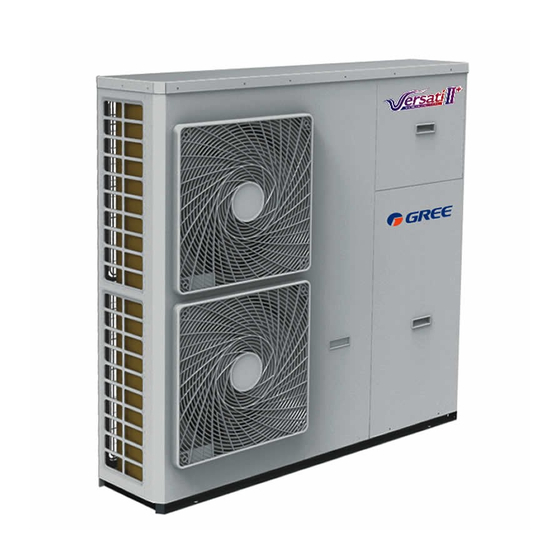
Summary of Contents for Gree Versati II+
- Page 1 Change for life Air-to-water Heat Pump Monobloc Versati Test Operation & Troubleshooting & Maintenance GREE ELECTRIC APPLIANCES, INC.OF ZHUHAI...
-
Page 2: Table Of Contents
CONTENTS 1 Trial Run �������������������������������������������������������������������������������������������������� 1 1.1 Check for Wiring ......................1 1.2 Check for the Water System ..................1 1.3 Check for the Communication System ............... 1 1.4 Trial Run ........................1 2 Error Code List ���������������������������������������������������������������������������������������� 1 3 Flow Chart Of Troubleshooting ������������������������������������������������������������� 3 3.1 Comp High-pressure Protection E1 ................ -
Page 3: Trial Run
When there is any error, solve it according to the troubleshooting flowchart covered in this manual. However, if the troubleshooting flowchart is still unhelpful, please contact GREE sales agent. 2 Error Code List No�... - Page 4 Test Operation & Troubleshooting & Maintenance High pressure protection High pressure Low pressure protection Low pressure High discharge protection Hi-discharge Refrigerant loss protection Refri-loss Heat pump-water pump protection HP-pump Solar kit-water pump protection SL-pump Swimming pool-water pump protection Swimming-pump Incorrect capacity DIP switch setting Capacity DIP Communication error between indoor and outdoor unit ODU-IDU Com.
-
Page 5: Flow Chart Of Troubleshooting
Test Operation & Troubleshooting & Maintenance Desynchronizing Desynchronize Compressor stalling Comp. stalling Communication error drive-main com. Radiator or IPM or PFC module overtemperature Overtemp.-mod. Radiator or IPM or PFC module temperature sensor error T-mod. sensor Charging circuit error Charge circuit Incorrect AC voltage input AC voltage Drive board temperature sensor error... -
Page 6: Comp Low-Pressure Protection E3
Test Operation & Troubleshooting & Maintenance 3�2 Comp Low- pressure Protection E3 Comp Low-pressure Protection E3 Replace comp Check if comp low-pressure switch low- pressure or rewire is broken or the wiring is loose. Check the fans Check if the fans stop running or reverse Repair the leakage of system pipe and add refrigerant Check if the system has leaked... -
Page 7: Overload Protection Of Compressor Or Driver Error
Test Operation & Troubleshooting & Maintenance 3�4 Overload Protection of Compressor or Driver Error Comp Overload Protection Check if the AC Replace the AC contactor contactor is damaged Adjust the Check if the compressor compressor wiring wiring is correct Contact the power Check if the voltage is normal supply company Recharge suitable... -
Page 8: Temperature Sensor Error
Test Operation & Troubleshooting & Maintenance 3�6 Temperature Sensor Error Temperature Sensor Error Check if the plug Check the orientation on temperature sensor is correctly of plug and socket connected to the socket. Check if the resistance of Replace the temperature sensor is correct. -
Page 9: Capacity Switch Error (Code:"C5")
Test Operation & Troubleshooting & Maintenance 3�8 Capacity Switch Error (Code:"C5") Communication Malfunction E6 Check if the communication Communication line of the unit is connected Malfunction E6 Communication Measure if the Communication Malfunction E6 line is through Check if the communication line Communication of the unit is connected correctly Malfunction E6... - Page 10 Test Operation & Troubleshooting & Maintenance “Driver reset”,“T-mod. sensor”, “AC curr. pro.”,“FPC defective” or “Current sen.” is displayed on the wired controller P0, P7, PA, HC or PC is displayed in the mainboard 88 indicating lamp Replace the driver board AP4 Work Normally 4�1�2 IPM or PFC Over-temperature Protection(Code:"P8") “Overtemp.-mod.”...
- Page 11 Test Operation & Troubleshooting & Maintenance 4�1�3 DC Busbar Over-voltage Protection(Code:"PH") ; DC Busbar Under-voltage Protection(Code:"PL") “DC over-vol.” or “DC under-vol.” is displayed on the wired controller PH or PL is displayed in the mainboard 88 Indicating Lamp Is input voltage ranged from 185VAC to 264VAC? Replace the mainboard.
- Page 12 Test Operation & Troubleshooting & Maintenance 4�1�5 Compressor Startup Failure(code:"LC") "Start failure" is displayed on the wired controller LC is displayed in the mainboard 88 indicating lamp driver board AP4. Replace Does it work Normally? Replace the compressor Work Normally 4�1�6 Compressor Current Protection (Code:"P5");...
-
Page 13: Daily Maintenance And Repair
Test Operation & Troubleshooting & Maintenance 4�1�7 Charging Circuit Error(Code:"PU") “Charge circuit” is displayed on the wired controller PU is displayed in the mainboard 88 indicating lamp Is the PFC wire tightened or is the sequence right? Tighten the PFC wire Replace or adjust the sequence the mainboard... -
Page 14: Troubleshooting
Test Operation & Troubleshooting & Maintenance 5�2 Troubleshooting Malfunctions Reasons Troubleshooting Power supply has problem. Phase sequence is reverse. ① ① Compressor does Connection wire is loose. Check out and re-fix. ② ② Malfunction of mainboard. Find out the reasons and repair. not start up ③... - Page 15 Test Operation & Troubleshooting & Maintenance It is installed at the side of the suction line, and used Vapor Liquid to prevent liquid refrigerant entering the compressor, Separator which if not avoided will lead to wet compression or even liquid slugging. It is used the switch flow direction of refrigerant and then realize switchover between cooling and 4-way Valve...
- Page 16 Test Operation & Troubleshooting & Maintenance It is used to prevent the heat exchanger from being frozen owing to reduced water flow rate. When the Flow Switch flow rate goes down to the point at which the flow switch will act, the switch will trip off and the unit will raise an alarm and shut down.
- Page 17 Test Operation & Troubleshooting & Maintenance Charging Charging valve 2 valve 1 Notes Discharge is allowed unless the unit has been stopped. (Cut off the power and repower it 1 minutes ① later) Protective measures should be taken during discharging to avoid frost bites. ②...


Need help?
Do you have a question about the Versati II+ and is the answer not in the manual?
Questions and answers