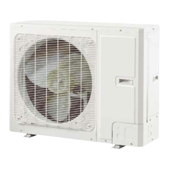
Gree VERSATI III Series Test Operation & Troubleshooting & Maintenance
Air to water
Hide thumbs
Also See for VERSATI III Series:
- Service manual (135 pages) ,
- Owner's manual (55 pages) ,
- Service manual (160 pages)
Summary of Contents for Gree VERSATI III Series
- Page 1 Test Operation & Troubleshooting & Maintenance VERSATI Ⅲ Air To Water Heat Pump TEST OPERATION & TROUBLESHOOTING & MAINTENANCE...
-
Page 2: Trial Run
When there is any error, solve it according to the troubleshooting flowchart covered in this manual. However, if the troubleshooting flowchart is still unhelpful, please contact GREE sales agent. 2 Error Code List... - Page 3 Test Operation & Troubleshooting & Maintenance Full Name Displayed Name Error Code Low pressure protection Low pressure High discharge protection Hi-discharge Refrigerant loss protection Refri-loss Heat pump-water pump protection HP-pump Solar kit-water pump protection SL-pump Incorrect capacity DIP switch setting Capacity DIP Communication error between indoor and outdoor unit ODU-IDU Com.
- Page 4 Test Operation & Troubleshooting & Maintenance Full Name Displayed Name Error Code Radiator or IPM or PFC module overtemperature Overtemp.-mod. Radiator or IPM or PFC module temperature sensor error T-mod. sensor Charging circuit error Charge circuit Incorrect AC voltage input AC voltage Drive board temperature sensor error Temp-driver...
-
Page 5: Flow Chart Of Troubleshooting
Test Operation & Troubleshooting & Maintenance 3 Flow Chart of Troubleshooting 3.1 Comp High-pressure Protection E1 Page 4... - Page 6 Test Operation & Troubleshooting & Maintenance 3.2 Comp Low- pressure Protection E3 3.3 Comp Discharge Temp Protection E4 Page 5...
- Page 7 Test Operation & Troubleshooting & Maintenance 3.4 Overload Protection of Compressor or Driver Error 3.5 DC Fan Error EF Page 6...
- Page 8 Test Operation & Troubleshooting & Maintenance 3.6 Temperature Sensor Error 3.7 Communication Malfunction E6 Page 7...
-
Page 9: Capacity Switch Error (Code:"C5")
Test Operation & Troubleshooting & Maintenance 3.8 Capacity Switch Error (Code:"C5") 4 Diagnosis of Driving 4.1 Diagnosis Flowchart of Driving of Single-phase Unit and Three-phase Unit Drive Module Reset(Code:"P0") ; IPM or PFC Temperature Sensor Error(Code:"P7") ; AC Current Protection (Input Side)(Code:"PA"); Current Sense Circuit Error(code:"PC"); PFC Protection(Code:"HC") Page 8... - Page 10 Test Operation & Troubleshooting & Maintenance IPM or PFC Over-temperature Protection(Code:"P8") DC Busbar Over-voltage Protection(Code:"PH") ; DC Busbar Under-voltage Protection (Code:"PL") Note: three-phase input voltage is in the range from 320VAC to 475VAC. Page 9...
- Page 11 Test Operation & Troubleshooting & Maintenance Drive-to-main-control Communication Error(Code:"P6") Compressor Startup Failure(code:"LC") Page 10...
- Page 12 Test Operation & Troubleshooting & Maintenance Compressor Current Protection (Code:"P5"); Compressor Motor Desynchronizing (Code:"H7"); IPM Protection (Code:"H5"); Phase Loss (Code:"LD") Charging Circuit Error(Code:"PU") Page 11...
-
Page 13: Daily Maintenance And Repair
Test Operation & Troubleshooting & Maintenance 5 Daily Maintenance and Repair 5.1 Daily Maintenance In order to avoid damage of unit, all protecting devices in the unit had been set before outgoing, so the user can never adjust or remove them. For the first startup of the unit or next startup of unit after long-period stop (above 1 day) by cutting off the power, please electrify the unit in advance to preheat the unit for more than 8hr Never put sundries on the unit and accessories. - Page 14 Test Operation & Troubleshooting & Maintenance Low load. it. Check water pump, valve and pipeline. Clean water filter or evacuate. Adjust the load or add accumulating devices. The unit does not Repair by leakage detection and add ...
-
Page 15: Key Components
Test Operation & Troubleshooting & Maintenance 5.3 Repair 5.3.1 Key Components Picture Name Function It is the heart of the cooling system, mainly used to turn the low-temperature, low-pressure refrigerant vapor to high-temperature high-pressure vapor and then discharge it to Compressor the evaporator. - Page 16 Test Operation & Troubleshooting & Maintenance Picture Name Function It is the water-refrigerant plate type heat exchanger, used to liquefy the high-temperature high-pressure vapor refrigerant or Plate Heat evaporate the low-temperature low pressure liquid refrigerant. Exchanger Heat of condensation is taken away by circulation water and heat for evaporation is supplied also by circulation water.
-
Page 17: Charging And Discharging Of Refrigerant
Test Operation & Troubleshooting & Maintenance Picture Name Function It is used to prevent the pressure of circulation water from Safety Valve increasing unusually. When the pressure is larger than the set point (0.6MPa), this valve will open to relieve water pressure. It is used to expel air trapped inside the water system to make Exhaust Valve sure normal operation of the system. - Page 18 Test Operation & Troubleshooting & Maintenance Note: when vacuuming is finished, pressure inside the unit should be kept lower than 80Pa for at least 30 minutes to make sure there is no leak. Either charging valve 1 or charging valve 2 can be used for vacuuming.
- Page 19 Test Operation & Troubleshooting & Maintenance Page 140 Total 139 JF00303839...


Need help?
Do you have a question about the VERSATI III Series and is the answer not in the manual?
Questions and answers