Advertisement
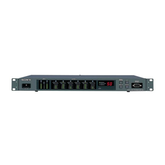
Digital Audio Processor
SRP-F300
Operating Instructions
INPUT
OUTPUT
1
2
A
B
C
D
COMP
LIMITER
IN-1
LIMITER
IN-1
LIMITER
IN-1
LIMITER
OVER
OVER
IN-2
OVER
IN-2
OVER
IN-2
OVER
-6
-6
HF
-6
HF
-6
HF
-6
-10
-10
MF
-10
MF
-10
MF
-10
-20
-20
LF
-20
LF
-20
LF
-20
-40
-40
8LF
-40
8LF
-40
8LF
-40
ON
OFF
Thank you for purchasing a Sony Digital Audio Processor.
Before operating, please read this manual carefully.
Be sure to keep it properly for future reference.
RECALL
/ENTER
UP
REMOTE
E
F
(RS-232C)
IN-1
LIMITER
IN-1
LIMITER
IN-1
PROGRAM
IN-2
OVER
IN-2
OVER
IN-2
OUTPUT STATUS
DISPLAY
DOWN
HF
-6
HF
-6
HF
REMOTE I/D
MF
-10
MF
-10
MF
LF
-20
LF
-20
LF
8LF
-40
8LF
-40
8LF
LOCK
DIGITAL AUDIO PROCESSOR SRP-F300
TABLE OF CONTENTS
WARNING...............................
PRECAUTIONS ........................
1 OUTLINE ..............................
FUNCTIONS .........................
OPERATION .........................
PROCESSING .......................
5 SPECIFICATIONS .................
6 DIMENSIONS ......................
In most set-ups, connect the RS-232C terminal to an
external computer. For external control see the attached
floppy disk, "Control Software Manual" and
"Communication Protocol Guide". These instructions detail
operation of the unit and its signal processing.
2-347-035-12 (1)
2
4
5
6
9
13
17
19
Advertisement
Table of Contents

Related Manuals for Sony SRP-F300


Summary of Contents for Sony SRP-F300
-
Page 1: Table Of Contents
PROCESSING ....... 5 SPECIFICATIONS ....6 DIMENSIONS ...... Thank you for purchasing a Sony Digital Audio Processor. Before operating, please read this manual carefully. Be sure to keep it properly for future reference. In most set-ups, connect the RS-232C terminal to an external computer. -
Page 2: Warning
WARNING Setting the voltage selector (voltage selector Notice for the Customers in the United Kingdom equipped models only) Check that the voltage selector on the rear panel is set IMPORTANT to the local power line voltage. If not, set the selector The wires in this mains lead are coloured in accor- dance with the following code: to the correct position using a screwdriver before... - Page 3 For the customers in Europe Für Kunden in Europa This product with the CE marking complies with both Dieses Produkt besitzt die CE-Kennzeichnung und the ECM Directive (89/336/EEC) and the Low erfülit sowohl die EMV-Direktive (89/336/EEC) als Voltage Directive (73/23/EEC) issued by the Com- auch die Dilevtive Niederspannung (73/23/EEC) der mission of the European Community.
-
Page 4: Precautions
Do not throw away the carton and the packing material. It makes an ideal container for transporting the unit. When shipping the unit for repair work or to another location, repack it as it was. If you have any questions or problems concerning your unit, consult your nearest Sony dealer. -
Page 5: Outline
Plenty of signal processing The SRP-F300 is capable of providing a 31-band graphic equalizers, an 11-band parametric equalizer, a compressor and a level control for 2-channels of input signals. For each of the 6-channel outputs, it accommodates low-and high-cut filtering up to 6th order for crossover, a 3-band parametric equalizer, a peak limiter, a delay, a phase switcher and a level control. -
Page 6: Parts Names And Functions
IN-2 OVER IN-2 OVER IN-2 OUTPUT STATUS DISPLAY DOWN REMOTE I/D LOCK DIGITAL AUDIO PROCESSOR SRP-F300 " $ COMP LIMITER IN-1 OVER OVER IN-2 Power Switch Output channel peak limiter indicator To turn the power on/off. When the unit is Illuminates when signal wave’s peak reaches the... - Page 7 RECALL/ENTER button It is used for RECALL of stored programs in the unit. (Refer to page 11) !¡ DISPLAY button Press the button to switch the display mode of the unit. (Refer to page 9) !™ UP button !£ DOWN button Use these buttons when you make the number +/–...
-
Page 8: Rear Panel
2-2. REAR PANEL REMOTE PUSH PUSH PUSH VOLTAGE SELECTOR RS-232C 120V 230V ~ AC IN ANALOG INPUT ANALOG OUTPUT DIGITAL INPUT 2-347-028-01 ANALOG INPUT terminals (IN-1, IN-2) DIGITAL INPUT terminal For analog audio signals. Inputs digital audio signals. Connector: Equivalent to XLR-3-31 (XLR-3-31 equivalent connector, compliant with 1: GND, 2: HOT, 3: COLD AES/EBU format) -
Page 9: Displays And Operation
3. DISPLAY AND OPERATION 3-1. Switching DISPLAY MODE You can change the display mode by pressing the DISPLAY button in turn. The DISPLAY mode indicator shows the current display. (Not available during external control) PROGRAM When PROGRAM is lit: OUTPUT STATUS REMOTE / ID The number display indicates the program number and each output channel indicator indicates the level at that output. - Page 10 When none of the indicaters are lit, it means that output channnel is muted. NOTE This frequency band indication is determined based on the cut-off frequency status of crossover filter of each channel. The relation of indication of the front panel and cut-off frequency status is as shown: 20Hz 100Hz...
- Page 11 3-3. Display and operation during external control You cannot use buttons on the front panel while you control with an external computer. In this case, three indicators of PROGRAM, REMOTE/ID and LOCK at DISPLAY mode indicator light up. PROGRAM OUTPUT STATUS REMOTE / ID LOCK The number of the display indicates the current program number and each output...
- Page 12 RECALL LOCK.) • When the LOCK indicator is lit, RECALL operation is impossible. 3-5. Changing REMOTE ID REMOTE ID is preset at factory to 01. It can only be changed on the SRP-F300 itself. DISPLAY Press DISPLAY button. Then REMOTE/ID indicator lights up and currently selected number displays set number displays.
-
Page 13: Built-In Signal Processing
4. BUILT-IN SIGNAL PROCESSING Signal Processing Block Chart INPUT-LEVEL IN-1 A-IN D-IN 31band GEQ Master Delay PEQ 11 band Compressor IN-2 A-IN D-IN 31band GEQ Master Delay Signal Generator PEQ 11 band Compressor Pink Sine Input Signal Block Master channel Block Refer to “Control Software Manual”... - Page 14 OUTPUT-LEVEL Peak Delay Phase Mute OUT-A 3 band Limiter Peak Delay Phase Mute OUT-B 3 band Limiter Peak Delay Phase Mute OUT-C 3 band Limiter Peak Delay Phase Mute OUT-D 3 band Limiter Peak Delay Phase Mute OUT-E 3 band Limiter Peak Delay...
- Page 15 4-3. Output channel processing block Each output channel is identical and can to be set independantly. • Selecting the input signal You can select the input source from master 2 channels from following 3 patterns. 1 Master IN-1 channel signal 2 Master IN-2 channel signal 3 Mono-mix signal of master 2 channels.
- Page 16 • Peak limiter Instantaneous waveform transformation type peak limiter. It can be set over a range of –20.0dBs~+6.0dBFs at 0.5dB steps. When signal reaches the limiting level, the limiter indicator is lit. Before processing (narrow line) After processing (wide line) Example of waveform of Peak Limiter Processing •...
-
Page 17: Specifications
5. SPECIFICATIONS Analog input : XLR-3-31 pin female × 2 Terminal Circuit : Electronic balanced (1: GND, 2: HOT, 3: COLD) Input impedance : 10kΩ Maximum input level : +24dBu A/D conversion : Sampling frequency 96kHz, 24bits linear Analog output : XLR-3-32 pin male ×... - Page 18 REMOTE terminal Terminal : D-sub 9 pin x 2 REMOTE RS-232C RxD (input) 1 2 3 4 5 TxD (output) Connect to pin 6 inside 6 7 8 9 Connect to pin 4 inside RTS (output) CTS (input) Format : RS-232C Use 9 pin cross-connection type cable to connect a computer.
-
Page 19: Dimensions
LIMITER IN-1 LIMITER IN-1 LIMITER IN-1 LIMITER IN-1 LIMITER IN-1 LIMITER IN-1 PROGRAM OVER OVER IN-2 OVER IN-2 OVER IN-2 OVER IN-2 OVER IN-2 OVER IN-2 OUTPUT STATUS DISPLAY DOWN REMOTE I/D LOCK DIGITAL AUDIO PROCESSOR SRP-F300 unit : mm... - Page 20 Printed in Japan...
Need help?
Do you have a question about the SRP-F300 and is the answer not in the manual?
Questions and answers