
Subscribe to Our Youtube Channel
Related Manuals for REI ST-3000


Summary of Contents for REI ST-3000
- Page 1 Heavy Duty AM/FM Stereo Weather Band Radio, w/Front-Panel Auxiliary Input and built in PA Radio Engineering Industries, Inc. www.radioeng.com Rev B.1 Date: 12-22-14 Installation/ Operation Manual 50W x 4 ST-3000...
- Page 2 Thank you for purchasing the ST-3000 AM/FM Weather Band Receiver from REI. SPECIFICATIONS This product is designed and tested to withstand temperature and vibration extremes. AUDIO SECTION Please read the owner’s manual carefully before attempting to install this unit. Power supply voltage (negative ground) ……………….……….12V DC (10V-18V) Standby Current…...……………………..…………..…………………………25mA...
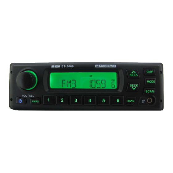
- Page 3 4. To remove the radio, insert the two release keys into the holes on the front face of CONTROLS AND INDICATORS the radio. The tools must be inserted with the notched side facing the radio. Slide the keys foreword until you hear a click. Then pull the radio out, releasing it from the DIN collar.
- Page 4 Pass the harness and antenna cable through the DIN collar, and connect to the OPERATION back of the radio. Verify clearance; then gently insert the radio into the DIN Collar 1) Power On/Off Button until both spring clips are locked into place. Press the Power Button to turn the unit ON or OFF.
- Page 5 While in either FM or AM tuner mode, press and hold the VOL/SEL button for 2 seconds. LCD will display MENU, press again to make a selection: The first option is to select a correct REI PA input based on the microphone type you Din Collar are using.
- Page 6 PA OPERATION (microphone sold separately) ELECTRICAL CONNECTIONS Follow this easy wiring diagram when installing Radio and Speakers. Connect a PA microphone into the 4-pin connector. Microphone has priority over all other audio modes and mute’s the source audio being played when keyed. When the Warning: *This radio is designed for 12V DC Negative Ground Systems Only.
Need help?
Do you have a question about the ST-3000 and is the answer not in the manual?
Questions and answers
How do I reset my radio and get rid of the MIC message on the LCD?
To remove the "MIC" message from the LCD on the REI ST-3000 radio, release the PA microphone trigger. The "MIC" display appears when the PA is triggered and will return to the previous source mode once the trigger is un-keyed.
This answer is automatically generated